6
Numbers, Variables, and Arithmetic
In this chapter you will
- Generate random numbers
- Create electronic dice
- Learn about binary numbers
- Use shift-register integrated circuits (ICs) to get more digital output pins
- Test your knowledge of binary numbers with a quiz
- Learn about arrays of variables
- Display numbers on seven-segment LED modules
- Learn how to use the modulo math function
- Create a digital thermometer
You will learn a wide variety of useful new functions that will create more project options, including random number generation, new kinds of math functions, and variable storage in ordered lists called arrays. Furthermore, you will learn how to use LED display modules in numeric form to display data and simple images. Finally, we’ll combine these tools to create a game, a digital thermometer, and more.
Generating Random Numbers
A program’s ability to generate random numbers can be very useful in games and effects. For example, you can use random numbers to play a dice or lottery game, create lighting effects with LEDs, or create visual or auditory effects for a quiz game with the Arduino. Unfortunately, the Arduino can’t choose a purely random number by itself. You have to help it by providing a seed, an arbitrary starting number used in the calculations to generate a random number.
Using Ambient Current to Generate a Random Number
The easiest way to generate a random number with the Arduino is to write a program that reads the voltage from a free (disconnected) analog pin (for example, analog pin 0) with this line in void setup():
randomSeed(analogRead(0));Even when nothing is wired to an analog input on the Arduino, static electricity in the environment creates a tiny, measurable voltage. The amount of this voltage is quite random. We can use this measure of ambient voltage as our seed to generate a random number and then allocate it to an integer variable using the random(lower, upper) function. Furthermore, we can use the parameters lower and upper to set the lower and upper limits of the range for the random number. For example, to generate a random number between 100 and 1,000, you would use the following:
int a = 0;
a = random(100, 1001);
We’ve used the number 1,001 rather than 1,000 because the upper limit is exclusive, meaning it’s not included in the range.
To generate a random number between 0 and some number, you can just enter the upper limit. Here’s how you would generate a random number between 0 and 6:
a = random(7);The example sketch in Listing 6-1 would generate a random number between 0 and 1,000 and another random number between 10 and 50.
// Listing 6-1
int r = 0;

void setup()
{
  randomSeed(analogRead(0));
  Serial.begin(9600);
}

void loop()
{
  Serial.print("Random number between zero and 1000 is: ");
  r = random(0, 1001);
  Serial.println(r);
  Serial.print("Random number between ten and fifty is: ");
  r = random(10, 51);
  Serial.println(r);
  delay(1000);
}
Listing 6-1: A random number generator
Figure 6-1 shows the result of Listing 6-1 in the Serial Monitor.

Figure 6-1: Output from Listing 6-1
Now that you know how to generate random numbers, let’s put that knowledge to good use by creating an electronic die.
Project #15: Creating an Electronic Die
Our goal is to light one of six LEDs randomly to mimic the throw of a die. We’ll choose a random number between 1 and 6, then turn on the corresponding LED to indicate the result. We’ll create a function to select one of six LEDs on the Arduino randomly and to keep the LED on for a certain period of time. When the Arduino running the sketch is turned on or reset, it should show random LEDs rapidly for a specified period of time and then gradually slow the flashing until the final LED is lit. The LED matching the resulting randomly chosen number will stay on until the Arduino is reset or turned off.
The Hardware
To build the die, we’ll need the following hardware:
- Six LEDs of any color (LED1 to LED6)
- One 560 Ω resistor (R1)
- Various connecting wires
- One medium-sized breadboard
- Arduino and USB cable
The Schematic
Because only one LED will be lit at a time, a single current-limiting resistor can go between the cathodes of the LEDs and GND. Figure 6-2 shows the schematic for our die.

Figure 6-2: Schematic for Project 15
The Sketch
Here’s the sketch for our die:
// Project 15 - Creating an Electronic Die
void setup()
{
  randomSeed(analogRead(0));      // seed the random number generator
  for ( int z = 1 ; z < 7 ; z++ ) // LEDs on pins 1-6 are output
  {
    pinMode(z, OUTPUT);
  }
}

void randomLED(int del)
{
  int r;
  r = random(1, 7);      // get a random number from 1 to 6
  digitalWrite(r, HIGH); // output to the matching LED on digital pin 1-6
  if (del > 0)
  {
1     delay(del);          // hold the LED on for the delay received
  }
2     else if (del == 0)
  {
    do                   // delay entered was zero, hold the LED on forever
    {}
3     while (1);
  }
  digitalWrite(r, LOW);  // turn off the LED
}

void loop()
{
  int a;
  // cycle the LEDs around for effect
  for ( a = 0 ; a < 100 ; a++ )
  {
    randomLED(50);
  }
  // slow down
4   for ( a = 1 ; a <= 10 ; a++ )
  {
    randomLED(a * 100);
  }
  // and stop at the final random number and LED
  randomLED(0);
}
Here we use a loop in void setup() to activate the digital output pins. The function randomLED() receives an integer that is used in the delay() function at 1 to keep the LED turned on for the selected time. If the value of the delay received at 2 is 0, then the function keeps the LED turned on indefinitely, because we use
do {} while (1);at 3, which loops forever, because 1 is always 1.
To “roll the die,” we reset the Arduino to restart the sketch. To gradually slow the change in the LEDs before the final value is displayed, we first display a random LED 100 times for 50 milliseconds each time. Then, at 4 we slow down the flashing by increasing the delay between LED flashes from 100 to 1,000 milliseconds, with each flash lasting 100 milliseconds. The purpose of this is to simulate the “slowing down” of a die before it finally settles on a value. With the last line, the Arduino displays the outcome of the roll by keeping one LED lit:
randomLED(0);Modifying the Sketch
We can tinker with this project in many ways. For example, we could add another six LEDs to roll two dice at once. Or display the result using only the built-in LED, by blinking it a number of times to indicate the result of the roll. Or use a button to roll the dice again. Use your imagination and new skills to have some fun!
A Quick Course in Binary
Most children learn to count using the base-10 system, but computers (including the Arduino) count using the binary number system.
Binary Numbers
Binary numbers consist of only 1s and 0s—for example, 10101010. In binary, each digit from right to left represents 2 to the power of the column number in which it appears (which increases from right to left). The products in each column are then added to determine the value of the number.
For example, consider the binary number 10101010, as shown in Table 6-1. To convert the number 10101010 in binary to base 10, we add the totals in each column as listed in the bottom row of the table:
128 + 0 + 32 + 0 + 8 + 0 + 2 + 0
The sum is 170, and therefore the binary number 10101010 equals 170 in base 10. A binary number with eight columns (or bits) holds 1 byte of data; 1 byte of data can have a numerical value between 0 and 255. The leftmost bit is referred to as the most significant bit (MSB), and the rightmost is the least significant bit (LSB).
Table 6-1: Binary to Base-10 Number Conversion Example
| 27 | 26 | 25 | 24 | 23 | 22 | 21 | 20 | |
| 1 | 0 | 1 | 0 | 1 | 0 | 1 | 0 | Binary |
| 128 | 64 | 32 | 16 | 8 | 4 | 2 | 1 | Base 10 |
Binary numbers are great for storing certain types of data, such as on/off patterns for LEDs, true/false settings, and the statuses of digital outputs. Binary numbers are the building blocks of all types of data in computers.
Byte Variables
One way we can store binary numbers is by using a byte variable. For example, we can create the byte variable outputs using the following code:
byte outputs = B11111111;The B in front of the number tells Arduino to read the number as a binary number (in this case, 11111111) instead of its base-10 equivalent of 255. Listing 6-2 demonstrates this further.
// Listing 6-2

byte a;

void setup()
{
  Serial.begin(9600);
}

void loop()
{
  for ( int count = 0 ; count < 256 ; count++ )
  {
    a = count;
    Serial.print("Base-10 = ");
1     Serial.print(a, DEC);
    Serial.print(" Binary = ");
2     Serial.println(a, BIN);
    delay(1000);
  }
}
Listing 6-2: Binary number demonstration
We display byte variables as base-10 numbers using DEC 1 or as binary numbers using BIN 2 as part of the Serial.print() function. After uploading the sketch, you should see output in the Serial Monitor similar to that shown in Figure 6-3.
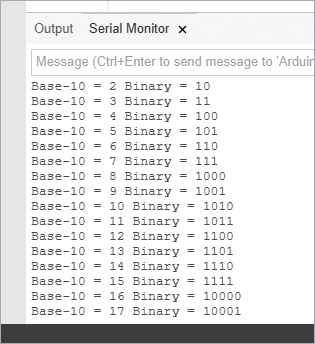
Figure 6-3: Output from Listing 6-2
Increasing Digital Outputs with Shift Registers
The Arduino board has 13 digital pins that we can use as outputs—but sometimes 13 just isn’t enough. To add outputs, we can use a shift register and still have plenty of room left on the Arduino for outputs. A shift register is an integrated circuit (IC) with eight digital output pins that can be controlled by sending a byte of data to the IC. For our projects, we will be using the 74HC595 shift register shown in Figure 6-4.

Figure 6-4: The 74HC595 shift register IC
The 74HC595 shift register has eight digital outputs that can operate like the Arduino digital output pins. The shift register itself takes up three Arduino digital output pins, so the net gain is five output pins.
The principle behind the shift register is simple: we send 1 byte of data (8 bits) to the shift register, and it turns on or off the matching eight outputs based on the 1 byte of data. The bits representing the byte of data match the output pins in order from highest to lowest, so the leftmost bit of the data represents output pin 7 of the shift register, and the rightmost bit of the data represents output pin 0. For example, if we send B10000110 to the shift register, then it will turn on outputs 1, 2, and 7 and will turn off outputs 0 and 3 to 6 until the next byte of data is received or the power is turned off.
More than one shift register can be connected together to provide an extra eight digital output pins for every shift register attached to the same three Arduino pins; this makes shift registers very convenient when you want to control lots of LEDs. Let’s do that now by creating a binary number display.
Project #16: Creating an LED Binary Number Display
In this project, we’ll use eight LEDs to display binary numbers from 0 to 255. Our sketch will use a for loop to count from 0 to 255 and will send each value to the shift register, which will use LEDs to display the binary equivalent of each number.
The Hardware
The following hardware is required:
- One 74HC595 shift register IC
- Eight LEDs (LED1 to LED8)
- Eight 560 Ω resistors (R1 to R8)
- One breadboard
- Various connecting wires
- Arduino and USB cable
The Schematic
Figure 6-5 shows the schematic symbol for the 74HC595.

Figure 6-5: 74HC595 schematic symbol
There are 16 pins on our shift register:
- Pins 15 and 1 to 7 are the eight output pins that we control (labeled Q0 to Q7, respectively).
- Q7 outputs the first bit sent to the shift register and Q0 outputs the last.
- Pin 8 connects to GND.
- Pin 9 is called data out and is used to send data to another shift register if one is present.
- Pin 10 is always connected to 5 V (for example, the 5 V connector on the Arduino).
- Pins 11 and 12 are called clock and latch.
- Pin 13 is called output enable and is usually connected to GND.
- Pin 14 is for incoming bit data sent from the Arduino.
- Pin 16 is used for power: 5 V from the Arduino.
To give you a sense of the way the pins are oriented, the semicircular notch on the left end of the body of the shift register IC shown in Figure 6-4 lies between pins 1 and 16.
The pins are numbered sequentially around the body in a counterclockwise direction, as shown in Figure 6-6, the schematic for our LED binary number display.
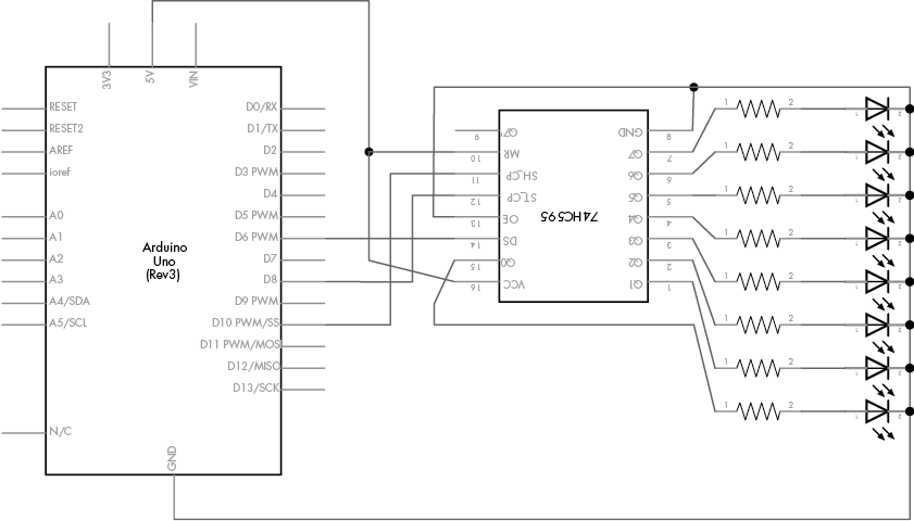
Figure 6-6: Schematic for Project 16
The Sketch
And now for the sketch:
// Project 16 – Creating an LED Binary Number Display
#define DATA  6          // digital 6 to pin 14 on the 74HC595
#define LATCH 8          // digital 8 to pin 12 on the 74HC595
#define CLOCK 10         // digital 10 to pin 11 on the 74HC595

void setup()
{
   pinMode(LATCH, OUTPUT);
   pinMode(CLOCK, OUTPUT);
   pinMode(DATA, OUTPUT);
}

void loop()
{
   int i;
   for ( i = 0; i < 256; i++ )
   {
     digitalWrite(LATCH, LOW);
     shiftOut(DATA, CLOCK, MSBFIRST, i);
     digitalWrite(LATCH, HIGH);
     delay(200);
   }
}
In this sketch, we set the three pins connected to the shift register as outputs in void setup() and then add a loop in void loop() that counts from 0 to 255 and repeats. The magic lies inside the loop. When we send a byte of data (for example, 240, or B11110000) to the shift register in the for loop, three things happen:
- The latch pin 12 is set to
LOW(that is, a low signal is applied to it from the Arduino digital output pin 8). This is preparation for setting output pin 12 toHIGH, which latches the data to the output pins aftershiftOut()has completed its task. - We send the byte of data (for example,
B11110000) from Arduino digital pin 6 to the shift register and tell theshiftOut()function from which direction to interpret the byte of data. For example, if we selectedLSBFIRST, then LEDs 1 to 4 would turn on and the others would turn off. If we usedMSBFIRST, then LEDs 5 to 8 would turn on and the others would turn off. - Finally, the latch pin 12 is set to
HIGH(5 V is applied to it). This tells the shift register that all the bits are shifted in and ready. At this point, the shift register alters its output to match the data received.
Project #17: Making a Binary Quiz Game
In this project, we’ll use random numbers, the Serial Monitor, and the circuit created in Project 16 to create a binary quiz game. The Arduino will display a random binary number using the LEDs, and then you will enter the decimal version of the binary number using the Serial Monitor. The Serial Monitor will tell you whether your answer is correct, and the game will continue with a new number.
The Algorithm
The algorithm can be divided into three functions. The displayNumber() function will display a binary number using the LEDs. The getAnswer() function will receive a number from the Serial Monitor and display it to the user. Finally, the checkAnswer() function will compare the user’s number to the random number generated and display the correct/incorrect status, as well as the correct answer if the guess was incorrect.
The Sketch
The sketch generates a random number between 0 and 255, displays it in binary using the LEDs, asks the user for their answer, and then displays the result in the Serial Monitor. You’ve already seen all the functions used in the sketch, so although there’s a lot of code here, it should look familiar. We’ll dissect it with comments within the sketch and some commentary following:
// Project 17 - Making a Binary Quiz Game

#define DATA   6                 // connect to pin 14 on the 74HC595
#define LATCH  8                 // connect to pin 12 on the 74HC595
#define CLOCK 10                 // connect to pin 11 on the 74HC595

int number = 0;
int answer = 0;

1 void setup()
{
  pinMode(LATCH, OUTPUT);        // set up the 74HC595 pins
  pinMode(CLOCK, OUTPUT);
  pinMode(DATA, OUTPUT);
  Serial.begin(9600);
  randomSeed(analogRead(0));     // initialize the random number generator
  displayNumber(0);              // clear the LEDs
}

2 void displayNumber(byte a)
{
  // send byte to be displayed on the LEDs
  digitalWrite(LATCH, LOW);

  shiftOut(DATA, CLOCK, MSBFIRST, a);
  digitalWrite(LATCH, HIGH);
}

3 void getAnswer()
{
  // receive the answer from the player
  int z = 0;
  Serial.flush();
  while (Serial.available() == 0)
  {
     // do nothing until something comes into the serial buffer
  }
     // one character of serial data is available, begin calculating
     while (Serial.available() > 0)
  {
    // move any previous digit to the next column on the left; in
    // other words, 1 becomes 10 while there is data in the buffer
    answer = answer * 10;
    // read the next number in the buffer and subtract the character '0'
    // from it to convert it to the actual integer number
    z = Serial.read() - '0';
    // add this digit into the accumulating value
    answer = answer + z;
    // allow a short delay for any more numbers to come into Serial.available
    delay(5);
  }
  Serial.print("You entered: ");
  Serial.println(answer);
}

4 void checkAnswer()
{
  // check the answer from the player and show the results
  if (answer == number)    // Correct!
  {
    Serial.print("Correct! ");
    Serial.print(answer, BIN);
    Serial.print(" equals ");
    Serial.println(number);
    Serial.println();
  }
  else                     // Incorrect
  {
    Serial.print("Incorrect, ");
    Serial.print(number, BIN);
    Serial.print(" equals ");
    Serial.println(number);
    Serial.println();
  }
  answer = 0;
  delay(10000); // give the player time to review their answer
}

5 void loop()
{
  number = random(256);
  displayNumber(number);
  Serial.println("What is the binary number in base 10? ");
  getAnswer();
  checkAnswer();
}
Let’s review how the sketch works. At 1, void setup() configures the digital output pins to use the shift register, starts the Serial Monitor, and seeds the random number generator. At 2, the custom function displayNumber() accepts a byte of data and sends it to the shift register, which uses LEDs to display the byte in binary form via the attached LEDs (as in Project 16). At 3, the custom function getAnswer() accepts a number from the user via the Serial Monitor (as in Project 14 in Chapter 5) and displays it, as shown in Figure 6-7.
The function checkAnswer() at 4 compares the number entered by the player in getAnswer() against the random number generated by the sketch in void loop(). The player is then advised of a correct or incorrect answer with corresponding binary and decimal values. Finally, in the main void loop() at 5 from which the program runs, the Arduino generates the random binary number for the quiz, calls the matching functions to display it with hardware, and then receives and checks the player’s answer.
Figure 6-7 shows the game in play in the Serial Monitor.

Figure 6-7: Project 17 in play
Arrays
An array is a set of variables or values grouped together so that they can be referenced as a whole. When dealing with lots of related data, you’ll find it a good idea to use arrays to keep your data organized.
Defining an Array
Each item in an array is called an element. For example, suppose six float variables contain temperatures taken over the last six hours; instead of giving them all separate names, we can define an array called temperatures with six elements like this:
float temperatures[6];We can also insert values when defining the array. When we do that, we don’t need to define the array size. Here’s an example:
float temperatures[]={11.1, 12.2, 13.3, 14.4, 15.5, 16.6};Notice that this time, we didn’t explicitly define the size of the array within the square brackets ([]); instead, its size is deduced based on the number of elements set by the values inside the curly brackets ({}). Note that arrays of any size can only contain one type of variable.
Referring to Values in an Array
We count the elements in an array beginning from the left and starting from 0; the temperatures[] array has elements numbered 0 to 5. We can refer to individual values within an array by inserting the number of the element in the square brackets. For example, to change the first element in temperatures[] (currently 11.1) to 12.34, we would use this:
temperatures[0] = 12.34;Writing to and Reading from Arrays
In Listing 6-3, we demonstrate writing values to and reading values from an array of five elements. The first for loop in the sketch writes a random number into each of the array’s elements, and the second for loop retrieves the elements and displays them in the Serial Monitor.
// Listing 6-3

void setup()
{
  Serial.begin(9600);
  randomSeed(analogRead(0));
}
int array[5];    // define our array of five integer elements
void loop()
{
  int i;
  Serial.println();
  for ( i = 0 ; i < 5 ; i++ )   // write to the array
  {
    array[i] = random(10);      // random numbers from 0 to 9
  }
  for ( i = 0 ; i < 5 ; i++ )   // display the contents of the array
  {
    Serial.print("array[");
    Serial.print(i);
    Serial.print("] contains ");
    Serial.println(array[i]);
  }
  delay(5000);
}
Listing 6-3: Array read/write demonstration
Figure 6-8 shows the output of this sketch in the Serial Monitor.
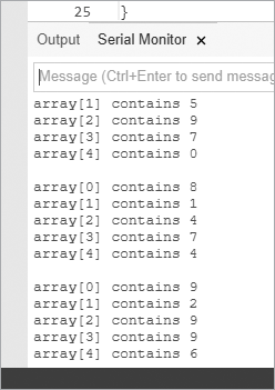
Figure 6-8: Listing 6-3 in action
Now that you know how to use with binary numbers, shift registers, and arrays, it’s time to put that knowledge to use. In our next project, we’ll wire up some digital number displays.
Seven-Segment LED Displays
LEDs are fun, but there are limits to the kinds of data that can be displayed with individual lights. In this section, we’ll begin working with numeric digits in the form of seven-segment LED displays, as shown in Figure 6-9.

Figure 6-9: Seven-segment display modules
These displays are perfect for displaying numbers, and that’s why you’ll find them used in digital alarm clocks, speedometers, and the like. Each module in a seven-segment LED display consists of eight LEDs. The modules are also available in different colors. To reduce the number of pins used by the display, all of the anodes or cathodes of the LEDs are connected together—these are called common-anode or common-cathode modules, respectively. Our projects will use common-cathode modules.
The display’s LEDs are labeled A to G and DP (for the decimal point). There is an anode pin for each LED segment, and the cathodes are connected to one common cathode pin. The layout of seven-segment LED displays is always described as shown in Figure 6-10, with LED segment A at the top, B to its right, and so on. So, for example, if you wanted to display the number 7, then you would apply current to segments A, B, and C.
The pins on each LED display module can vary, depending on the manufacturer, but they always follow the basic pattern shown in Figure 6-10. When you use one of these modules, always get the data sheet for the module from the retailer to help save you time determining which pins are which.
We’ll use the schematic symbol shown in Figure 6-11 for our seven-segment LED display modules.
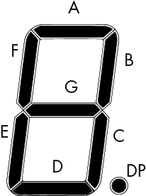
Figure 6-10: LED map for a typical seven-segment display module
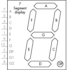
Figure 6-11: Schematic symbol for a seven-segment display module
Controlling the LED
We’ll control the LED display using the method discussed in Project 17, by connecting pins A through DP to the shift register outputs Q0 to Q7. Use the matrix shown in Table 6-2 as a guide to help determine which segments to turn on and off to display a particular number or letter.
The top row in the matrix is the shift register output pin that controls the segments on the second row. Each row below this shows the digit that can be displayed with the corresponding binary and decimal value to send to the shift register.
Table 6-2: Display Segment Matrix
| SR | Q0 | Q1 | Q2 | Q3 | Q4 | Q5 | Q6 | Q7 | |
| Segment | A | B | C | D | E | F | G | DP | Decimal |
| 0 | 1 | 1 | 1 | 1 | 1 | 1 | 0 | 0 | 252 |
| 1 | 0 | 1 | 1 | 0 | 0 | 0 | 0 | 0 | 96 |
| 2 | 1 | 1 | 0 | 1 | 1 | 0 | 1 | 0 | 218 |
| 3 | 1 | 1 | 1 | 1 | 0 | 0 | 1 | 0 | 242 |
| 4 | 0 | 1 | 1 | 0 | 0 | 1 | 1 | 0 | 102 |
| 5 | 1 | 0 | 1 | 1 | 0 | 1 | 1 | 0 | 182 |
| 6 | 1 | 0 | 1 | 1 | 1 | 1 | 1 | 0 | 190 |
| 7 | 1 | 1 | 1 | 0 | 0 | 0 | 0 | 0 | 224 |
| 8 | 1 | 1 | 1 | 1 | 1 | 1 | 1 | 0 | 254 |
| 9 | 1 | 1 | 1 | 1 | 0 | 1 | 1 | 0 | 246 |
| A | 1 | 1 | 1 | 0 | 1 | 1 | 1 | 0 | 238 |
| B | 0 | 0 | 1 | 1 | 1 | 1 | 1 | 0 | 62 |
| C | 1 | 0 | 0 | 1 | 1 | 1 | 0 | 0 | 156 |
| D | 0 | 1 | 1 | 1 | 1 | 0 | 1 | 0 | 122 |
| E | 1 | 0 | 0 | 1 | 1 | 1 | 1 | 0 | 158 |
| F | 1 | 0 | 0 | 0 | 1 | 1 | 1 | 0 | 142 |
For example, to display the digit 7, as shown in Figure 6-12, we need to turn on LED segments A, B, and C, which correspond to the shift register outputs Q0, Q1, and Q2. Therefore, we will send the byte B1110000 into the shift register (with shiftOut() set to LSBFIRST) to turn on the first three outputs that match the desired LEDs on the module.

Figure 6-12: Displaying the digit 7
In our next project, we’ll create a circuit that displays, in turn, the digits 0 through 9 and then the letters A through F. The cycle repeats with the decimal-point LED turned on.
Project #18: Creating a Single-Digit Display
In this project we’ll assemble a circuit to use a single-digit display.
The Hardware
The following hardware is required:
- One 74HC595 shift register IC
- One common-cathode seven-segment LED display
- One 560 Ω resistor (R1)
- One large breadboard
- Various connecting wires
- Arduino and USB cable
The Schematic
The schematic is shown in Figure 6-13.

Figure 6-13: Schematic for Project 18
When you’re wiring the LED module to the shift register, LED pins A through G connect to pins Q0 through Q6, respectively, and DP connects to Q7.
The Sketch
In the sketch for Project 18, we store the decimal values (see Table 6-2) in the int digits[] array. In the void loop(), we send these values to the shift register in sequential order at 1 and then repeat the process with the decimal point on by adding 1 to the value sent to the shift register at 2:
// Project 18 - Creating a Single-Digit Display
#define DATA  6                       // connect to pin 14 on the 74HC595
#define LATCH 8                       // connect to pin 12 on the 74HC595
#define CLOCK 10                      // connect to pin 11 on the 74HC595

// set up the array with the segments for 0 to 9, A to F (from Table 6-2)
int digits[] = {252, 96, 218, 242, 102, 182, 190, 224, 254, 246, 238, 62, 156, 122, 158, 142};

void setup()
{
  pinMode(LATCH, OUTPUT);
  pinMode(CLOCK, OUTPUT);
  pinMode(DATA, OUTPUT);
}

void loop()
{
  int i;
  for ( i = 0 ; i < 16 ; i++ )   // display digits 0-9, A-F
  {
    digitalWrite(LATCH, LOW);
1 shiftOut(DATA, CLOCK, LSBFIRST, digits[i]);
    digitalWrite(LATCH, HIGH);
    delay(250);
  }
  for ( i = 0 ; i < 16 ; i++ )   // display digits 0-9, A-F with DP
  {
    digitalWrite(LATCH, LOW);
2 shiftOut(DATA, CLOCK, LSBFIRST, digits[i]+1); // +1 is to turn on the DP bit
    digitalWrite(LATCH, HIGH);
    delay(250);
  }
}
Seven-segment LED displays are bright and easy to read. For example, Figure 6-14 shows the result when this sketch is asked to display the digit 9 with the decimal point.

Figure 6-14: Digit displayed by Project 18
Modifying the Sketch: Displaying Double Digits
To use more than one shift register to control additional digital outputs, connect pin 9 of the 74HC595 (which receives data from the Arduino) to pin 14 of the second shift register. Once you’ve made this connection, two bytes of data will be sent: the first to control the second shift register and the second to control the first shift register. Here’s an example:
  digitalWrite(LATCH, LOW);
  shiftOut(DATA, CLOCK, MSBFIRST, 254); // data for second 74HC595
  shiftOut(DATA, CLOCK, MSBFIRST, 254); // data for first 74HC595
  digitalWrite(LATCH, HIGH);
Project #19: Controlling Two Seven-Segment LED Display Modules
This project will show you how to control two seven-segment LED display modules so that you can display two-digit numbers.
The Hardware
The following hardware is required:
- Two 74HC595 shift register ICs
- Two common-cathode seven-segment LED displays
- Two 560 Ω resistors (R1 to R2)
- One large breadboard or two smaller units
- Various connecting wires
- Arduino and USB cable
The Schematic
Figure 6-15 shows the schematic for two display modules.
Note that the shift registers’ data and clock pins are connected to each other and then to the Arduino. The data line from Arduino digital pin 6 runs to shift register 1, and then a link from pin 9 of shift register 1 runs to pin 14 of shift register 2.
To display a number between 0 and 99, we’ll need a more complicated sketch. If a number is less than 10, we can just send the number followed by a 0, as the right digit will display the number and the left digit will display 0. However, if the number is greater than 10, then we need to determine each of the number’s two digits and send each to the shift registers separately. To make this process easier, we’ll use the math function modulo.

Figure 6-15: Schematic for Project 19
Modulo
Modulo is a function that returns the remainder of a division operation. For example, 10 modulo (or mod) 7 equals 3—in other words, the remainder of 10 divided by 7 equals 3. We use the percent sign (%) to represent modulo. The following example uses modulo in a sketch:
int a = 8;
int b = 3;
int c = a % b;
In this example, the value of c will be 2. So, to determine a two-digit number’s right-hand digit, we use the modulo function, which returns the remainder when dividing the two numbers.
To automate displaying a single- or double-digit number, we’ll create the function displayNumber() for our sketch. We use modulo as part of this function to separate the digits of a two-digit number. For example, to display the number 23, we first isolate the left-hand digit by dividing 23 by 10, yielding 2 (and a fraction that we can ignore). To isolate the right-hand digit, we perform 23 modulo 10, which equals 3:
// Project 19 - Controlling Two Seven-Segment LED Display Modules
// set up the array with the segments for 0 to 9, A to F (from Table 6-2)

#define DATA  6            // connect to pin 14 on the 74HC595
#define LATCH 8            // connect to pin 12 on the 74HC595
#define CLOCK 10           // connect to pin 11 on the 74HC595

void setup()
{
  pinMode(LATCH, OUTPUT);
  pinMode(CLOCK, OUTPUT);
  pinMode(DATA, OUTPUT);
}

int digits[] = {252, 96, 218, 242, 102, 182, 190, 224, 254, 246, 238, 62, 156, 122, 158, 142};
void displayNumber(int n)
{
  int left, right=0;
1   if (n < 10)
  {
    digitalWrite(LATCH, LOW);
    shiftOut(DATA, CLOCK, LSBFIRST, digits[n]);
    shiftOut(DATA, CLOCK, LSBFIRST, 0);
    digitalWrite(LATCH, HIGH);
  }
  else if (n >= 10)
  {
2     right = n % 10; // remainder of dividing the number to display by 10
    left = n / 10;  // quotient of dividing the number to display by 10
    digitalWrite(LATCH, LOW);
    shiftOut(DATA, CLOCK, LSBFIRST, digits[right]);
    shiftOut(DATA, CLOCK, LSBFIRST, digits[left]);
    digitalWrite(LATCH, HIGH);
  }
}
3 void loop()
{
  int i;
  for ( i = 0 ; i < 100 ; i++ )
  {
    displayNumber(i);
    delay(100);
  }
}
At 1, the function checks whether the number to be displayed is less than 10. If so, it sends the data for the number and a blank digit to the shift registers. However, if the number is greater than 10, the function uses modulo and division at 2 to separate the digits and then sends them to the shift registers separately. Finally, in void loop() at 3, we set up and call the function to display the numbers from 0 to 99.
Project #20: Creating a Digital Thermometer
In this project, we’ll add the TMP36 temperature sensor we created in Project 8 in Chapter 4 to the double-digit circuit constructed for Project 19 to create a digital thermometer that displays values for 0 degrees and above. The algorithm is simple: we read the voltage returned from the TMP36 (using the method from Project 12 in Chapter 5) and convert the reading to degrees Celsius.
The Hardware
The following hardware is required:
- The double-digit circuit from Project 19
- One TMP36 temperature sensor
Connect the center output lead of the TMP36 to analog pin 5, the left lead to 5 V, and the right lead to GND, and you’re ready to measure.
The Sketch
Here is the sketch:
// Project 20 - Creating a Digital Thermometer
#define DATA  6             // connect to pin 14 on the 74HC595
#define LATCH 8             // connect to pin 12 on the 74HC595
#define CLOCK 10            // connect to pin 11 on the 74HC595

int temp = 0;
float voltage = 0;
float celsius = 0;
float sensor = 0;
int digits[]={
  252, 96, 218, 242, 102, 182, 190, 224,
  254, 246, 238, 62, 156, 122, 158, 142
};

void setup()
{
  pinMode(LATCH, OUTPUT);
  pinMode(CLOCK, OUTPUT);
  pinMode(DATA, OUTPUT);
}

void displayNumber(int n)
{
  int left, right = 0;
  if (n < 10)
  {
    digitalWrite(LATCH, LOW);
    shiftOut(DATA, CLOCK, LSBFIRST, digits[n]);
    shiftOut(DATA, CLOCK, LSBFIRST, digits[0]);
    digitalWrite(LATCH, HIGH);
  }
  if (n >= 10)
  {
    right = n % 10;
    left = n / 10;
    digitalWrite(LATCH, LOW);
    shiftOut(DATA, CLOCK, LSBFIRST, digits[right]);
    shiftOut(DATA, CLOCK, LSBFIRST, digits[left]);
    digitalWrite(LATCH, HIGH);

  }
}

void loop()
{
  sensor = analogRead(5);
  voltage = (sensor * 5000) / 1024; // convert raw sensor value to millivolts
  voltage = voltage - 500;          // remove voltage offset
  celsius = voltage / 10;           // convert millivolts to Celsius
  temp = int(celsius); // change the floating-point temperature to an int
  displayNumber(temp);
  delay(500);
}
As indicated, the sketch borrows code from previous projects: displayNumber() from Project 19 and the temperature calculations from Project 12. The delay(500) function in the second-to-last line of the sketch keeps the display from changing too quickly when the temperature fluctuates.
Looking Ahead
In this chapter, you have learned a lot of fundamental skills that you’ll use over and over in your own projects. LED displays are relatively hardy, so enjoy experimenting with them. However, there is a limit to the display effects they can be used for, so in the next chapter, we make use of much more detailed display methods for text and graphics.