11
Numeric Keypads
In this chapter you will
- Learn how to connect numeric keypads to your Arduino
- Read values from the keypad in a sketch
- Expand on decision systems with the
switch casestatement - Create a PIN-controlled lock or switch
Using a Numeric Keypad
As your projects become more involved, you might want to accept numeric input from users when your Arduino isn’t connected to a device with a keyboard. For example, you might like the ability to turn something on or off by entering a secret number. One option would be to wire up 10 or more push buttons to various digital input pins (for the numbers 0 through 9), but it’s much easier to use a numeric keypad like the one shown in Figure 11-1.

Figure 11-1: A numeric keypad
One of the benefits of using a keypad is that it uses only 8 pins for 16 active buttons, and with the use of a clever Arduino library, you won’t need to add pull-down resistors for debouncing as we did in Chapter 4.
At this point, you will need to download and install the Arduino Keypad library, which is available from https://github.com/Chris--A/Keypad/archive/master.zip.
Wiring a Keypad
Physically wiring the keypad to the Arduino is easy. With the keypad facing up, take a look at the end of the ribbon cable. You’ll see eight female connectors in a row, as shown in Figure 11-2.

Figure 11-2: The keypad connector
Reading from left to right, the sockets are numbered from 8 to 1. For all the keypad projects in this book, you’ll plug the keypad pins into the Arduino pins as shown in Table 11-1.
Table 11-1: Keypad-to-Arduino Connections
| Keypad pin number | Arduino pin |
| 8 | Digital 9 |
| 7 | Digital 8 |
| 6 | Digital 7 |
| 5 | Digital 6 |
| 4 | Digital 5 |
| 3 | Digital 4 |
| 2 | Digital 3 |
| 1 | Digital 2 |
Programming for the Keypad
When you write a sketch for the keypad, you must include certain lines of code to enable the keypad, as identified in Listing 11-1. The required code starts at 1 and ends at 5.
// Listing 11-1
1 // Beginning of keypad configuration code
#include <Keypad.h>

const byte ROWS = 4; // set display to four rows
const byte COLS = 4; // set display to four columns

2 char keys[ROWS][COLS] = {
  {'1','2','3','A'},
  {'4','5','6','B'},
  {'7','8','9','C'},
  {'*','0','#','D'}
};
3 byte rowPins[ROWS] = {9, 8, 7, 6};
4 byte colPins[COLS] = {5, 4, 3, 2};

Keypad keypad = Keypad( makeKeymap(keys), rowPins, colPins, ROWS, COLS );
5 // End of keypad configuration code

void setup()
{
  Serial.begin(9600);
}

void loop(){
  char key = keypad.getKey();

  if (key){
    Serial.print(key);
  }
}
Listing 11-1: Numeric keypad demonstration sketch
At 2, we introduce keys, a char variable array that contains one or more letters, numbers, or symbols that can be generated with a computer keyboard. In this case, it contains the numbers and symbols that your Arduino can expect from the keypad.
The lines of code at 3 and 4 define which digital pins are used on the Arduino. Using these lines and Table 11-1, you can change the digital pins used for input if you want.
Testing the Sketch
After uploading the sketch, open the Serial Monitor and press some keys on the keypad. The characters for the keys you pressed will be displayed in the Serial Monitor, as shown in Figure 11-3.
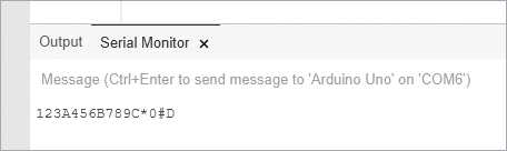
Figure 11-3: The result of pressing keys on the keypad
Making Decisions with switch case
When you need to compare two or more variables against another value, you’ll often find it easier and neater to use a switch case statement instead of an if then statement, because switch case statements can make an indefinite number of comparisons and run code when the comparison returns true. For example, if we had the integer variable xx with a possible value of 1, 2, or 3 and we wanted to run different code based on whether the value was 1, 2, or 3, we could use code like the following to replace our if then statement:
switch(xx)
{
  case 1:
  // do something when the value of xx is 1
  break;  // finish and move on with sketch
  case 2:
  // do something when the value of xx is 2
  break;
  case 3:
  // do something when the value of xx is 3
  break;
  default:
  // do something if xx is not 1, 2 or 3
  // default is optional
}
The optional default: section at the end of this code segment lets you choose to run some code when true comparisons no longer exist in the switch case statement.
Project #32: Creating a Keypad-Controlled Lock
In this project, we’ll start to create a keypad-controlled lock. We’ll use the basic setup described in the sketch in Listing 11-1, but we’ll also include a six-digit secret code that a user needs to enter on the keypad. The Serial Monitor will tell the user whether the code they’ve input is correct or not.
The secret code is stored in the sketch but is not displayed to the user. The sketch will call different functions depending on whether the input code (PIN) is correct. To activate and deactivate the lock, the user must press * and then the secret number, followed by #.
The Sketch
Enter and upload this sketch:
// Project 32 - Creating a Keypad-Controlled Lock
// Beginning of necessary code
#include <Keypad.h>

const byte ROWS = 4; // set display to four rows
const byte COLS = 4; // set display to four columns

char keys[ROWS][COLS] = {
  {'1','2','3','A'},
  {'4','5','6','B'},
  {'7','8','9','C'},
  {'*','0','#','D'}
};
byte rowPins[ROWS] = {9, 8, 7, 6};
byte colPins[COLS] = {5, 4, 3, 2};

Keypad keypad = Keypad( makeKeymap(keys), rowPins, colPins, ROWS, COLS );

// End of necessary code
1 char PIN[6]={'1','2','3','4','5','6'}; // our secret number
char attempt[6]={0,0,0,0,0,0};
int z=0;
void setup()
{
  Serial.begin(9600);
}
void correctPIN()   // do this if the correct PIN is entered
{
  Serial.println("Correct PIN entered...");
}
void incorrectPIN() // do this if an incorrect PIN is entered
{
  Serial.println("Incorrect PIN entered!");
}
void checkPIN()
{
  int correct=0;

2   for (int i = 0;
  i < 6 ;
  i++ )
  {
// Goes step-by-step through the 6-character array.
// If each char matches each char in the PIN, increments the
// counter.
if (attempt[i]==PIN[i])
    {
      correct++;
    }
  }
  if (correct==6)
  {
3     correctPIN();
  }
  else
  {
4     incorrectPIN();
  }
  for (int i=0; i<6; i++) // removes previously entered code attempt
  {
    attempt[i]=0;
  }
}
void readKeypad()
{
  char key = keypad.getKey();
  if (key != NO_KEY)
  {
5     switch(key)
    {
    case '*':
      z=0;
      break;
    case '#':
      delay(100); // removes the possibility of switch bounce
      checkPIN();
      break;
    default:
      attempt[z]=key;
      z++;
    }
  }
}
void loop()
{
6   readKeypad();
}
Understanding the Sketch
After the usual setup routines (as described in Listing 11-1), the sketch continually “listens” to the keypad by running the function readKeypad() at 6. After a key is pressed, the Arduino examines the value of the key using a switch case statement at 5. The Arduino stores the values of the keys pressed on the keypad in the array attempt, and when the user presses #, the Arduino calls the function checkPIN().
At 2, the Arduino compares the values of the pressed keys against the PIN stored in the array PIN at 1. If the correct sequence is entered, the function correctPIN() at 3 is called, where you can add your own code to execute. If an incorrect sequence is entered, the function incorrectPIN() at 4 is called. Finally, once the user’s entry has been checked, the code deletes the entry from memory so the code is ready for the next test.
Testing the Sketch
After you’ve uploaded the sketch to your Arduino, open the Serial Monitor window, press star (*) on the numeric keypad, type the secret number, and then enter the pound sign (#). Try entering both correct and incorrect numbers. Your results should be similar to the output shown in Figure 11-4.
This example serves as a perfect foundation for your own PIN-activated devices, such as locks, alarms, or anything else you can imagine. Just be sure to replace the code in correctPIN() and incorrectPIN() with the code you want to run when a correct or incorrect sequence is entered.

Figure 11-4: Results from entering correct and incorrect PINs
Looking Ahead
You have learned yet another way to gather input for your Arduino. You’ve also gained the foundational knowledge to create a useful method of controlling a sketch using a numeric keypad, as well as the foundations for a combination lock to access anything that your Arduino can control. Furthermore, you’ve learned the very useful switch case statement. In the next chapter, you’ll learn about another form of input: the touchscreen.