This chapter discusses advanced OSPF configuration. It covers the following topics:
This chapter introduces advanced operation, configuration, and verification of the Open Shortest Path First (OSPF) protocol. The different types of OSPF routers and link-state advertisements (LSAs) are introduced. Understanding the contents of the OSPF link-state database (LSDB) and IP routing table is key to understanding OSPF operation; both are investigated in this chapter. OSPF does not automatically summarize routes; route summarization configuration is covered, so that routing table size and the number of updates are reduced. Default routes are introduced next, followed by types of stub areas; both of these also reduce routing table size and the number of updates. Virtual links—links that allow discontiguous area 0s to be connected—are explored. The chapter concludes with a discussion of OSPF authentication configuration.
This section first describes the various OSPF router types, including backbone routers, area border routers (ABRs), autonomous system boundary routers (ASBRs), and internal routers. Each of the common LSA types and how they form the layout of the OSPF LSDB are then introduced.
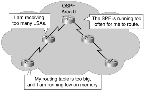
OSPF can operate within a single area; however issues may arise if the single area expands into hundreds of networks, as shown in Figure 5-1.
If an area becomes too big, the following issues need to be addressed:
Frequent shortest path first (SPF) algorithm calculations—. In a large network, changes are inevitable; therefore, the routers spend many CPU cycles recalculating the SPF algorithm and updating the routing table.
Large routing table—. OSPF does not perform route summarization by default. If the routes are not summarized, the routing table can become very large, depending on the size of the network.
Large LSDB—. Because the LSDB covers the topology of the entire network, each router must maintain an entry for every network in the area, even if not every route is selected for the routing table.
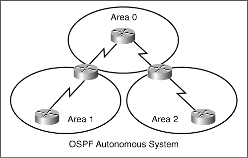
A solution to these issues is to divide the network into multiple OSPF areas. OSPF allows the separation of a large area into smaller, more manageable areas that still can exchange routing information.
Hierarchical area routing, shown in Figure 5-2, is OSPF’s ability to separate a large internetwork into multiple areas. Using this technique, interarea routing still occurs, but many of the internal routing operations, such as SPF calculations, can remain within individual areas. For example, if area 1 is having problems with a link going up and down, routers in other areas do not need to continually run their SPF calculation, because they can be isolated from the problem in area 1.
Assuming a proper IP addressing hierarchy is in place, using multiple OSPF areas has several important advantages:
Reduced frequency of SPF calculations—. Because detailed route information exists within each area, it is not necessary to flood all link-state changes to all other areas. Therefore, only routers that are affected by the change need to recalculate the SPF algorithm.
Smaller routing tables—. With multiple areas, detailed route entries for specific networks within an area can remain in the area. Instead of advertising these explicit routes outside the area, routers can be configured to summarize the routes into one or more summary addresses. Advertising these summaries reduces the number of LSAs propagated between areas but keeps all networks reachable.
Reduced link-state update (LSU) overhead—. LSUs contain a variety of LSA types, including link-state and summary information. Rather than send an LSU about each network within an area, a router can advertise a single summarized route or a small number of routes between areas, thereby reducing the overhead associated with LSUs when they cross areas.
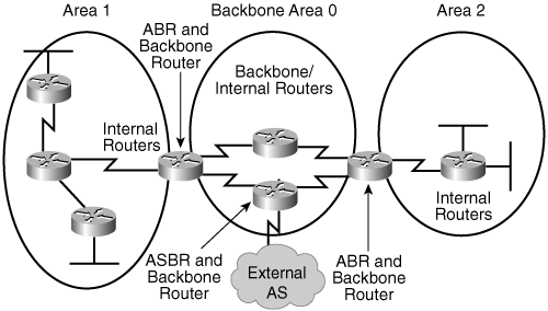
Certain types of OSPF routers control the traffic types that go in and out of various areas. The following are the four router types, as shown in Figure 5-3:
Internal router—. Routers that have all of their interfaces in the same area; all routers within the same area have identical LSDBs.
Backbone router—. Routers that sit in the perimeter of the backbone area and that have at least one interface connected to area 0. Backbone routers maintain OSPF routing information using the same procedures and algorithms as internal routers.
ABR—. Routers that have interfaces attached to multiple areas, maintain separate LSDBs for each area to which they connect, and route traffic destined for or arriving from other areas. ABRs are exit points for the area, which means that routing information destined for another area can get there only via the ABR of the local area. ABRs can be configured to summarize the routing information from the LSDBs of their attached areas. ABRs distribute the routing information into the backbone. The backbone routers then forward the information to the other ABRs. An area can have one or more ABRs.
ASBR—. Routers that have at least one interface attached to an external internetwork (another autonomous system [AS]), such as a non-OSPF network. ASBRs can import non-OSPF network information to the OSPF network and vice versa; this process is called route redistribution (and is covered in Chapter 7, “Manipulating Routing Updates”).
A router can be more than one router type. For example, if a router interconnects to area 0 and area 1, and to a non-OSPF network, it is both an ABR and an ASBR.
A router has a separate LSDB for each area to which it connects. Therefore, an ABR will have one LSDB for area 0 and another LSDB for the other area in which it participates. Two routers belonging to the same area maintain identical LSDBs for that area.
An LSDB is synchronized between pairs of adjacent routers. On broadcast networks such as Ethernet, an LSDB is synchronized between the DROTHER (a router that is not a Designated Router [DR] or a Backup Designated Router [BDR]) and its DR and BDR.
LSAs are the building blocks of the OSPF LSDB. Table 5-1 summarizes the types of LSAs.
Individually, LSAs act as database records; in combination, they describe the entire topology of an OSPF network or area. The following are descriptions of each type of LSA (with LSA types 1 to 5 explained in more detail in the following sections):
Type 1—. Every router generates router-link advertisements for each area to which it belongs. Router-link advertisements describe the states of the router’s links to the area and are flooded only within a particular area. All types of LSAs have 20-byte LSA headers. One of the fields of the LSA header is the link-state ID. The link-state ID of the type 1 LSA is the originating router’s ID.
Type 2—. DRs generate network link advertisements for multiaccess networks, which describe the set of routers attached to a particular multiaccess network. Network link advertisements are flooded in the area that contains the network. The link-state ID of the type 2 LSA is the DR’s IP interface address.
Types 3 and 4—. ABRs generate summary link advertisements. Summary link advertisements describe the following interarea routes:
Type 3 describes routes to the area’s networks (and may include aggregate routes).
Type 4 describes routes to ASBRs.
The link-state ID is the destination network number for type 3 LSAs and the router ID of the described ASBR for type 4 LSAs.
These LSAs are flooded throughout the backbone area to the other ABRs. Type 3 and type 4 LSAs are not flooded into totally stubby areas or totally stubby NSSAs. (Stub areas and NSSAs are discussed later in this chapter in the “OSPF Special Area Types” section.)
Type 5—. ASBRs generate autonomous system external link advertisements. External link advertisements describe routes to destinations external to the autonomous system and are flooded everywhere except to stub areas, totally stubby areas, and NSSAs. The link-state ID of the type 5 LSA is the external network number.
Type 6—. These LSAs are used in multicast OSPF applications.
Type 8—. These LSAs are used to internetwork OSPF and BGP.
Types 9, 10, or 11—. These LSA types are designated for future upgrades to OSPF for application-specific purposes. For example, Cisco Systems uses opaque LSAs for Multiprotocol Label Switching (MPLS) with OSPF. Standard LSDB flooding mechanisms are used to distribute opaque LSAs. Each of the three types has a different flooding scope.
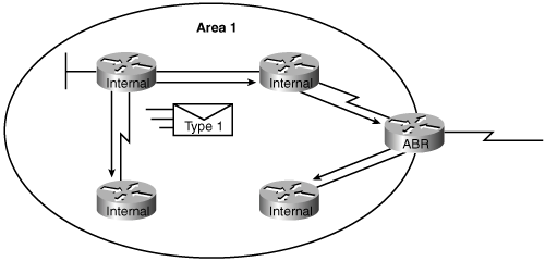
A router advertises a type 1 LSA that floods to all other routers in the area where it originated, as shown in Figure 5-4. A type 1 LSA describes the collective states of the router’s directly connected links (interfaces).
Each type 1 LSA is identified by the originating router’s ID in the link-state ID field.
Each of the router’s links (interfaces) is defined as one of four types: type 1, 2, 3, or 4. The LSA includes a link ID field to identify what is on the other end of the link; depending on the link type, the link ID field has different meanings. Type 1 LSA link types and their link ID meanings are described in Table 5-2.
Note
A stub network is a dead-end link that has only one router attached. A virtual link is a special case in OSPF (and is described later in this chapter in the “OSPF Special Area Types” section).
A link data field is also specified for each link, providing 32 bits of extra information. For most link types this is the IP interface address of the associated router interface. For links to stub networks, this field provides the stub network’s subnet mask.
In addition, the type 1 LSA indicates the OSPF cost for each link, and whether the router is an ABR or ASBR.
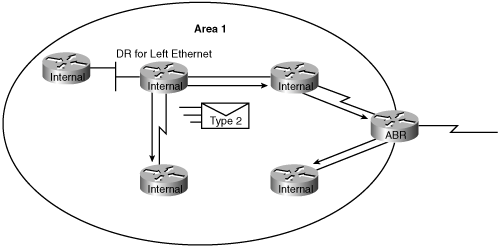
A type 2 LSA is generated for every transit broadcast or nonbroadcast multiaccess (NBMA) network within an area. A transit network has at least two directly attached OSPF routers, as shown in Figure 5-5. A multiaccess network such as Ethernet is an example of a transit network. A type 2 network LSA lists each of the attached routers that make up the transit network, including the DR itself, and the subnet mask of the link.
The transit link’s DR is responsible for advertising the network LSA. The type 2 LSA then floods to all routers within the transit network area. Type 2 LSAs never cross an area boundary. The link-state ID for a network LSA is the IP interface address of the DR that advertises it.
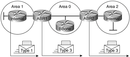
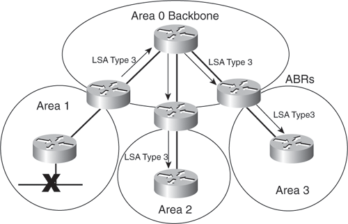
The ABR sends type 3 summary LSAs. A type 3 LSA advertises any networks owned by an area to the rest of the areas in the OSPF autonomous system, as shown in Figure 5-6.
Key Point: Type 3 LSAs Represent the Area’s Type 1 LSAs
As Figure 5-6 illustrates, type 1 LSAs stay within an area. When an ABR receives type 1 LSAs from other routers within an area, it sends out type 3 summary LSAs to advertise the networks learned via these type 1 LSAs to other areas.
By default, OSPF does not automatically summarize groups of contiguous subnets, or even summarize a network to its classful boundary. The network operator, through configuration commands, must specify if and how the summarization will occur. Therefore, by default, a type 3 LSA is advertised into the backbone area for every subnet defined in the originating area, which can cause significant flooding problems. Consequently, manual route summarization at the ABR should always be considered. ABRs flood summary LSAs regardless of whether the routes listed in the LSAs are summarized. (OSPF route summarization is discussed later in this chapter, in the “OSPF Route Summarization” section.)
A type 4 summary LSA is used only when an ASBR exists within an area. A type 4 LSA identifies the ASBR and provides a route to it. The link-state ID is set to the ASBR’s router ID. All traffic destined for an external autonomous system requires routing table knowledge of the ASBR that originated the external routes.
In Figure 5-7, the ASBR sends a type 1 router LSA with a bit (known as the external bit [e bit]) that is set to identify itself as an ASBR. When the ABR (identified with the border bit [b bit] in the router LSA) receives this type 1 LSA, it builds a type 4 LSA and floods it to the backbone, area 0. Subsequent ABRs regenerate a type 4 LSA to flood into their area.
Key Point: Type 4 LSAs
As Figure 5-7 again illustrates, type 1 LSAs stay within an area. When an ABR receives a type 1 LSA from an ASBR, it sends out a type 4 summary LSA to advertise the presence of the ASBR to other areas.
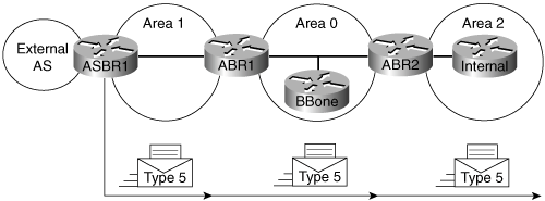
Type 5 external LSAs describe routes to networks outside the OSPF autonomous system. Type 5 LSAs are originated by the ASBR and are flooded to the entire autonomous system, as shown in Figure 5-8. Because of the flooding scope and depending on the number of external networks, the default lack of route summarization can also be a major issue with external LSAs. The network operator should always attempt to summarize blocks of external network numbers at the ASBR to reduce flooding problems.
This section explains the relationship between and how to interpret the OSPF LSDB and routing table. This section also describes the OSPF LSDB overload protection feature and how to change the OSPF cost metric.
Example 5-1 illustrates output from the show ip ospf database command, used to get information about an OSPF LSDB, on an ABR. In this output, the router link states are type 1 LSAs, the net link states are type 2 LSAs, the summary net link states are type 3 LSAs, the summary ASB link states are type 4 LSAs, and the external link states are type 5 LSAs. (This output is from the P1R1 router in Configuration Exercise 5-3, later in this chapter.)
Example 5-1. show ip ospf database Command
P1R1#show ip ospf database

            OSPF Router with ID (10.0.0.11) (Process ID 1)

                Router Link States (Area 0)

Link ID         ADV Router      Age         Seq#       Checksum Link count
10.0.0.11       10.0.0.11       485         0x80000004 0x002EE5 2
10.0.0.12       10.0.0.12       540         0x80000002 0x0046CB 2
10.0.0.21       10.0.0.21       494         0x80000042 0x00F8E1 1
10.0.0.22       10.0.0.22       246         0x80000042 0x00F6E0 1
200.200.200.200 200.200.200.200 485         0x800001CB 0x00E504 6

                Summary Net Link States (Area 0)

Link ID         ADV Router      Age         Seq#       Checksum
10.1.0.0        10.0.0.11       486         0x8000001A 0x00C92A
10.1.0.0        10.0.0.12       541         0x8000001A 0x00C32F
10.1.1.0        10.0.0.11       486         0x8000001A 0x002BD6
10.1.1.0        10.0.0.12       521         0x8000001C 0x00BE30
10.1.2.0        10.0.0.11       486         0x8000001A 0x00BD33
10.1.2.0        10.0.0.12       521         0x8000001C 0x0016E7
10.1.3.0        10.0.0.11       487         0x8000001A 0x00B23D
10.1.3.0        10.0.0.12       527         0x80000001 0x00DE29
10.2.0.0        10.0.0.21       1759        0x8000003F 0x00378C
10.2.0.0        10.0.0.22       856         0x8000003F 0x003191
10.2.1.0        10.0.0.21       1861        0x80000041 0x00943B
10.2.1.0        10.0.0.22       856         0x8000003F 0x003090
10.2.2.0        10.0.0.21       1861        0x80000049 0x00179F
10.2.2.0        10.0.0.22       1359        0x80000044 0x007D4D
10.2.3.0        10.0.0.21       1861        0x8000003F 0x00209F
10.2.3.0        10.0.0.22       1359        0x80000041 0x0016A6
10.11.0.0       10.0.0.11       589         0x80000018 0x005596
10.11.0.0       10.0.0.12       619         0x80000001 0x007D84

                Router Link States (Area 1)

Link ID         ADV Router      Age         Seq#       Checksum Link count
10.0.0.11       10.0.0.11       613         0x80000006 0x000CF1 5
10.0.0.12       10.0.0.12       614         0x80000006 0x00F205 5
10.200.200.13   10.200.200.13   639         0x80000005 0x0006B4 3
10.200.200.14   10.200.200.14   635         0x80000005 0x00882C 3

                Net Link States (Area 1)

Link ID         ADV Router      Age         Seq#       Checksum
10.1.1.1        10.0.0.11       640         0x80000001 0x00D485
10.1.2.2        10.0.0.12       635         0x80000001 0x00D183

                Summary Net Link States (Area 1)

Link ID         ADV Router      Age         Seq#       Checksum
172.31.11.1     10.0.0.11       616         0x80000001 0x002F21
172.31.11.1     10.0.0.12       576         0x80000001 0x0064CA
172.31.11.2     10.0.0.11       576         0x80000001 0x0060CE
172.31.11.2     10.0.0.12       670         0x80000001 0x001F2F
172.31.11.4     10.0.0.11       576         0x80000001 0x00AE8E
172.31.11.4     10.0.0.12       630         0x80000001 0x00A893
172.31.22.4     10.0.0.11       576         0x80000001 0x0035FC
172.31.22.4     10.0.0.12       630         0x80000001 0x002F02

                Summary ASB Link States (Area 1)

Link ID         ADV Router      Age         Seq#       Checksum
200.200.200.200 10.0.0.11       576         0x80000001 0x00688B
200.200.200.200 10.0.0.12       631         0x80000001 0x006290

                Type-5 AS External Link States

Link ID         ADV Router      Age         Seq#       Checksum Tag
10.254.0.0      200.200.200.200 451         0x8000019D 0x00DADD 0
P1R1#
The database columns in Example 5-1 are as follows:
Link ID—. Identifies each LSA.
ADV Router—. Advertising router—the LSA’s source router.
Age—. The maximum age counter in seconds. The maximum age is 1 hour, or 3600 seconds.
Seq#—. The LSA’s sequence number. It begins at 0x80000001 and increases with each update of the LSA.
Checksum—. Checksum of the individual LSA to ensure reliable receipt of that LSA.
Link count—. The total number of directly attached links; used only on router LSAs. The link count includes all point-to-point, transit, and stub links. Point-to-point serial links count as two; all other links, including Ethernet links, count as one.
Table 5-3 describes each of the routing table designators for OSPF.
Table 5-3. Types of OSPF Routes
Route Designator | Description | |
|---|---|---|
O | OSPF intra-area (router LSA) and network LSA | Networks from within the router’s area. Advertised by way of router LSAs and network LSAs. |
O IA | OSPF interarea (summary LSA) | Networks from outside the router’s area but within the OSPF autonomous system. Advertised by way of summary LSAs. |
O E1 | Type 1 external routes | Networks from outside the router’s autonomous system, advertised by way of external LSAs. |
O E2 | Type 2 external routes | Networks from outside the router’s autonomous system, advertised by way of external LSAs. The difference between E1 and E2 external routes is described in the “Calculating the Costs of E1 and E2 Routes” section. |
Router and network LSAs describe the details within an area. The routing table reflects this link-state information with a designation of O, meaning that the route is an intra-area.
When an ABR receives summary or external LSAs, it adds them to its LSDB and regenerates and floods them into the local area. The internal routers then assimilate the information into their databases. Summary LSAs appear in the routing table as IA (interarea) routes. External LSAs appear in the routing table marked as external type 1 (E1) or external type 2 (E2) routes.
The SPF algorithm is then run against the LSDB to build the SPF tree, which is used to determine the best paths. The following is the order in which the best paths are calculated:
All routers calculate the best paths to destinations within their area (intra-area) and add these entries to the routing table. These are the type 1 and type 2 LSAs, which are noted in the routing table with a routing designator of O (OSPF).
All routers calculate the best paths to the other areas in the internetwork. These best paths are the interarea route entries, or type 3 and type 4 LSAs. They are noted with a routing designator of O IA (interarea).
All routers (except those that are in the form of a stub area) calculate the best paths to the external autonomous system (type 5) destinations; these are noted with either an O E1 or O E2 route designator, depending on the configuration.
At this point, a router can communicate with any network within or outside the OSPF autonomous system.
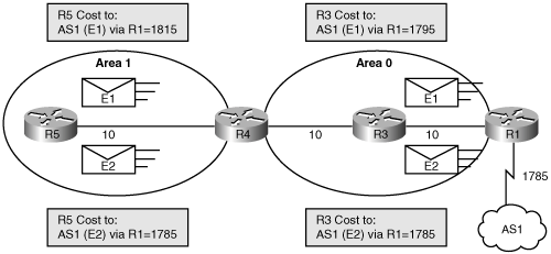
The cost of an external route varies, depending on the external type configured on the ASBR, as shown in Figure 5-9.
The following external packet types can be configured:
E1—. Type O E1 external routes calculate the cost by adding the external cost to the internal cost of each link the packet crosses. Use this type when multiple ASBRs are advertising an external route to the same autonomous system, to avoid suboptimal routing.
E2 (default)—. The external cost of O E2 packet routes is always the external cost only. Use this type if only one ASBR is advertising an external route to the autonomous system.
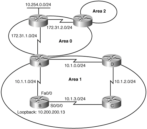
The show ip route command output shown in Example 5-2 depicts both external type routes (O E2) and interarea (O IA) routes. This output is taken from Router B in Figure 5-10.
Example 5-2. show ip route Command Output with an External OSPF Route
RouterB>show ip route
<output omitted>
Gateway of last resort is not set
     172.31.0.0/24 is subnetted, 2 subnets
O IA    172.31.2.0 [110/1563] via 10.1.1.1, 00:12:35, FastEthernet0/0
O IA    172.31.1.0 [110/782] via 10.1.1.1, 00:12:35, FastEthernet0/0
     10.0.0.0/8 is variably subnetted, 6 subnets, 2 masks
C       10.200.200.13/32 is directly connected, Loopback0
C       10.1.3.0/24 is directly connected, Serial0/0/0
O       10.1.2.0/24 [110/782] via 10.1.3.4, 00:12:35, Serial0/0/0
C       10.1.1.0/24 is directly connected, FastEthernet0/0
O       10.1.0.0/24 [110/782] via 10.1.1.1, 00:12:37, FastEthernet0/0
O E2 10.254.0.0/24 [110/50] via 10.1.1.1, 00:12:37, FastEthernet0/0In Example 5-2, the last entry (O E2) is an external route from the ASBR, via the ABR. The two numbers in brackets [110/50] are the administrative distance and the total cost of the route to the specific destination network, respectively. In this case, the administrative distance is set to the default for all OSPF routes of 110, and the total cost of the route has been calculated as 50.
If other routers are misconfigured, causing, for example, a redistribution of a large number of prefixes, large numbers of LSAs can be generated. These excessive LSAs can drain local CPU and memory resources. OSPF LSDB overload protection can be configured to protect against this issue with Cisco IOS Software Release 12.3(7)T and later (and some specific earlier releases) by using the max-lsa maximum-number [threshold-percentage] [warning-only] [ignore-time minutes] [ignore-count count-number] [reset-time minutes] router configuration command.
Table 5-4 lists the parameters of the max-lsa command.
Table 5-4. max-lsa Command Parameters
Parameter | Description |
|---|---|
maximum-number | Maximum number of non-self-generated LSAs that the OSPF process can keep in the OSPF LSDB. |
threshold-percentage | (Optional) The percentage of the maximum LSA number, as specified by the maximum-number argument, at which a warning message is logged. The default is 75 percent. |
warning-only | (Optional) Specifies that only a warning message is sent when the maximum limit for LSAs is exceeded; the OSPF process never enters ignore state. Disabled by default. |
ignore-time minutes | (Optional) Specifies the time, in minutes, to ignore all neighbors after the maximum limit of LSAs has been exceeded. The default is 5 minutes. |
ignore-count count-number | (Optional) Specifies the number of times that the OSPF process can consecutively be placed into the ignore state. The default is five times. |
reset-time minutes | (Optional) Specifies the time, in minutes, after which the ignore count is reset to 0. The default is 10 minutes. |
When this feature is enabled, the router keeps count of the number of received (non-self-generated) LSAs that it keeps in its LSDB. An error message is logged when this number reaches a configured threshold number, and a notification is sent when it exceeds the threshold number.
If the LSA count still exceeds the threshold after one minute, the OSPF process takes down all adjacencies and clears the OSPF database; this is called the ignore state. In this ignore state, no OSPF packets are sent or received by interfaces that belong to that OSPF process.
The OSPF process remains in the ignore state for the time that is defined by the ignore-time parameter. The ignore-count parameter defines the maximum number of times that the OSPF process can consecutively enter the ignore state before remaining permanently down and requiring manual intervention.
If the OSPF process remains normal for the time that is defined by the reset-time parameter, the ignore state counter is reset to 0.
By default, OSPF calculates the OSPF metric for an interface according to the inverse of the interface’s bandwidth. In general, the cost in Cisco routers is calculated using the formula 100 Mbps/(bandwidth in Mbps). For example, a 64-Kbps link gets a metric of 1562, and a T1 link gets a metric of 64. However, this formula is based on a maximum bandwidth of 100 Mbps, which results in a cost of 1. If you have faster interfaces, you may want to recalibrate the cost of 1 to a higher bandwidth.
When you are using the interface’s bandwidth to determine OSPF cost, always remember to use the bandwidth value interface configuration command to accurately define the bandwidth per interface, in kilobits per second.
If interfaces that are faster than 100 Mbps are being used, you should use the auto-cost reference-bandwidth ref-bw router configuration command. Use this command on all routers in the network to ensure accurate route calculations.
The parameter for the auto-cost reference-bandwidth command is described in Table 5-5.
To override the default cost, manually define the cost using the ip ospf cost interface-cost configuration command on a per-interface basis. The interface-cost is an integer from 1 to 65,535. The lower the number, the better (and more preferred) the link.
Route summarization involves consolidating multiple routes into a single advertisement. Proper route summarization directly affects the amount of bandwidth, CPU, and memory resources consumed by the OSPF routing process.
Without route summarization, every specific-link LSA is propagated into the OSPF backbone and beyond, causing unnecessary network traffic and router overhead. Whenever an LSA is sent, all affected OSPF routers have to recompute their LSDB and the SPF tree using the SPF algorithm.
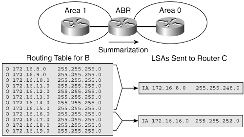
With route summarization, only summarized routes propagate into the backbone (area 0), as shown in Figure 5-11. This summarization is important because it prevents every router from having to rerun the SPF algorithm, increases the network’s stability, and reduces unnecessary LSA flooding. Also, if a network link fails, the topology change is not propagated into the backbone (and other areas by way of the backbone). Specific-link LSA flooding outside the area does not occur.
Key Point: Summary LSAs Do Not Contain Summarized Routes
Recall that summary LSAs (type 3 LSAs) and external LSAs (type 5 LSAs) by default do not contain summarized routes. By default, summary LSAs are not summarized.
The two types of summarization are as follows:
Interarea route summarization—. Interarea route summarization occurs on ABRs and applies to routes from within each area. It does not apply to external routes injected into OSPF via redistribution. To perform effective interarea route summarization, network numbers within areas should be assigned contiguously so that these addresses can be summarized into a minimal number of summary addresses. (Figure 5-12 later illustrates interarea summarization at the ABR for area 1.)
External route summarization—. External route summarization is specific to external routes that are injected into OSPF via route redistribution. Again, it is important to ensure the contiguity of the external address ranges that are being summarized. Summarizing overlapping ranges from two different routers can cause packets to be sent to the wrong destination. Generally, only ASBRs summarize external routes.
OSPF is a classless routing protocol, which means that it carries subnet mask information along with route information. Therefore, OSPF supports multiple subnet masks for the same major network, known as variable-length subnet masking (VLSM). OSPF also supports discontiguous subnets, because subnet masks are part of the LSDB. However, other protocols, such as Routing Information Protocol Version 1 (RIPv1), do not support VLSMs or discontiguous subnets. If the same major network crosses the boundaries of an OSPF and RIPv1 domain, VLSM information redistributed into RIPv1 is lost, and static routes have to be configured in the RIPv1 domain.
Key Point: Contiguous Address Assignment
Network numbers in areas should be assigned contiguously to ensure that these addresses can be summarized into a minimal number of summary addresses.
For example, in Figure 5-12, the list of 12 networks in router B’s routing table can be summarized into two summary address advertisements. The block of addresses from 172.16.8.0 to 172.16.15.0/24 can be summarized using 172.16.8.0/21, and the block from 172.16.16.0 to 172.16.19.0/24 can be summarized using 172.16.16.0/22.
OSPF does not perform autosummarization on major network boundaries. To manually configure interarea route summarization on an ABR, use the following procedure:
Configure OSPF.
Use the area area-id range address mask [advertise | not-advertise] [cost cost] router configuration command, described in Table 5-6, to instruct the ABR to summarize routes for a specific area before injecting them into a different area via the backbone as type 3 summary LSAs.
Table 5-6. area range Command Parameters
Description | |
|---|---|
area-id | Identifies the area subject to route summarization. |
address | The summary address designated for a range of addresses. |
mask | The IP subnet mask used for the summary route. |
advertise | (Optional) Sets the address range status to advertise and generates a type 3 summary LSA. |
not-advertise | (Optional) Sets the address range status to DoNotAdvertise. The type 3 summary LSA is suppressed, and the component networks remain hidden from other networks. |
cost | (Optional) Metric or cost for this summary route, which is used during the OSPF SPF calculation to determine the shortest paths to the destination. The value can be 0 to 16777215. |
The Cisco IOS Software creates a summary route to interface null 0 when manual summarization is configured, to prevent routing loops. For example, if the summarizing router receives a packet to an unknown subnet that is part of the summarized range, the packet matches the summary route based on the longest match. The packet is forwarded to the null 0 interface (in other words, it is dropped), which prevents the router from forwarding the packet to a default route and possibly creating a routing loop.
To configure manual route summarization on an ASBR to summarize external routes, use the following procedure:
Configure OSPF.
Use the summary-address ip-address mask [not-advertise] [tag tag] router configuration command, described in Table 5-7, to instruct the ASBR to summarize external routes before injecting them into the OSPF domain as a type 5 external LSA.
Table 5-7. summary-address Command Parameters
Parameter
Description
ip-address
The summary address designated for a range of addresses
mask
The IP subnet mask used for the summary route
not-advertise
(Optional) Used to suppress routes that match the address/mask pair
tag tag
(Optional) A tag value that can be used as a “match” value to control redistribution via route maps
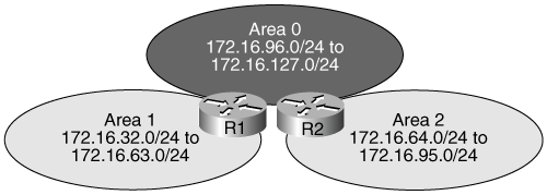
Figure 5-13 shows that route summarization can occur in both directions on an ABR—from a nonbackbone area to area 0 and from area 0 to a nonbackbone area. Example 5-3 illustrates the R1 and R2 configurations. For example, the R1 configuration specifies the following summarization:
area 0 range 172.16.96.0 255.255.224.0—. Identifies area 0 as the area containing the range of networks to be summarized into area 1. The ABR R1 summarizes the range of subnets from 172.16.96.0 to 172.16.127.0 into one range: 172.16.96.0 255.255.224.0.
area 1 range 172.16.32.0 255.255.224.0—. Identifies area 1 as the area containing the range of networks to be summarized into area 0. The ABR R1 summarizes the range of subnets from 172.16.32.0 to 172.16.63.0 into one range: 172.16.32.0 255.255.224.0.
Example 5-3. Enabling OSPF Routing on R1 and R2 in Figure 5-13
Router1(config)#router ospf 100
Router1(config-router)#network 172.16.32.1 0.0.0.0 area 1
Router1(config-router)#network 172.16.96.1 0.0.0.0 area 0
Router1(config-router)#area 0 range 172.16.96.0 255.255.224.0
Router1(config-router)#area 1 range 172.16.32.0 255.255.224.0

Router2(config)#router ospf 100
Router2(config-router)#network 172.16.64.1 0.0.0.0 area 2
Router2(config-router)#network 172.16.127.1 0.0.0.0 area 0
Router2(config-router)#area 0 range 172.16.96.0 255.255.224.0
Router2(config-router)#area 2 range 172.16.64.0 255.255.224.0
Note
Depending on your network topology, you may not want to summarize area 0 networks into other areas. For example, if you have more than one ABR between an area and the backbone area, sending a type 3 (summary) LSA with the explicit network information into an area ensures that the shortest path to destinations outside the area is selected. If you summarize the addresses, suboptimal path selection may occur.
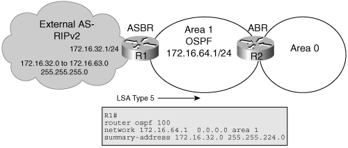
Figure 5-14 depicts route summarization on an ASBR. On the left, an external autonomous system running RIPv2 has its routes redistributed into OSPF. Because of the contiguous subnet block in the external RIP network, it is possible to summarize the 32 different subnets into one summarized route.
Instead of 32 external type 5 LSAs flooding into the OSPF network, there is only 1.
Note
RIPv2 routes must also be redistributed into OSPF in this example; redistribution is covered in Chapter 7.
You may want to configure OSPF to advertise a default route into its autonomous system, as described in this section.
Figure 5-15 shows how OSPF injects a default route into a standard area (the different types of areas are covered in the “OSPF Special Area Types” section later in this chapter). Any OSPF router can originate default routes injected into a standard area. However, OSPF routers do not, by default, generate a default route into the OSPF domain. For OSPF to generate a default route, you must use the default-information originate command.
There are two ways to advertise a default route into a standard area. The first is to advertise 0.0.0.0 into the OSPF domain, provided that the advertising router already has a default route. The second is to advertise 0.0.0.0 regardless of whether the advertising router already has a default route. (The second method can be accomplished by adding the keyword always to the default-information originate command, as described in the next section.)
A default route shows up in the OSPF database as an external LSA type 5, as shown in Example 5-4.
To generate a default external route into an OSPF routing domain, use the default-information originate [always] [metric metric-value] [metric-type type-value] [route-map map-name] router configuration command.
To disable this feature, use the no form of the command. Table 5-8 explains the options of the default-information originate command.
Table 5-8. default-information originate Command Parameters
Parameter | Description |
|---|---|
always | (Optional) Specifies that OSPF always advertises the default route regardless of whether the router has a default route in the routing table. |
metric metric-value | (Optional) A metric used for generating the default route. If you omit a value and do not specify a value using the default-metric router configuration command, the default metric value is 1. Cisco IOS Software documentation indicates that the default metric value is 10; testing shows that it is actually 1. Refer to the “default-information originate Command Actual Behavior” sidebar for more details. |
metric-type type-value | (Optional) External link type that is associated with the default route that is advertised into the OSPF routing domain. It can be one of the following values: 1—Type 1 external route 2—Type 2 external route. The default is type 2 external route (indicated by O*E2 in the routing table). |
route-map map-name | (Optional) Specifies that the routing process generates the default route if the route map is satisfied. |
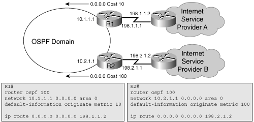
Figure 5-16 shows an OSPF network multihomed to dual Internet service providers (ISPs). The optional metric parameter has been used to prefer the default route to ISP A. The default route being generated has a metric-type of E2 by default, so the metric does not increase as it goes through the area. As a result, all routers, regardless of their proximity to the border router, prefer ISP A over ISP B.
Note
The default-information originate command causes the router to send a default route to all its OSPF neighbors. In Figure 5-16, notice that the R1 and R2 routers are not running OSPF on their connections to the ISP routers, and are therefore not passing a default route to the ISP routers.
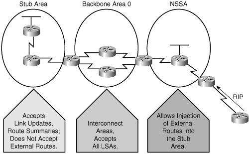
The characteristics assigned to an area control the type of route information it receives. The purpose behind any type of stub area is to inject default routes into an area so that external and/or summary LSAs are not flooded into the area. This reduces the LSDB size and the routing table size in the routers within the area. The possible area types, some of which are shown in Figure 5-17, are as follows:
Standard area—. This default area accepts link updates, route summaries, and external routes.
Backbone area (transit area)—. The backbone area is the central entity to which all other areas connect. The backbone area is labeled area 0. All other areas connect to this area to exchange and route information. The OSPF backbone has all the properties of a standard OSPF area.
Stub area—. This area does not accept information about routes external to the autonomous system, such as routes from non-OSPF sources. If routers need to route to networks outside the autonomous system, they use a default route, indicated as 0.0.0.0. Stub areas cannot contain ASBRs (except that the ABRs may also be ASBRs).
Totally stubby area—. This area does not accept external autonomous system routes or summary routes from other areas internal to the autonomous system. If a router needs to send a packet to a network external to the area, it sends the packet using a default route. Totally stubby areas cannot contain ASBRs (except that the ABRs may also be ASBRs).
NSSA—. NSSA is an addendum to the OSPF Requests for Comments (RFC). This area defines a special LSA type 7. NSSA offers benefits that are similar to those of a stub or totally stubby area. However, NSSAs allow ASBRs, which is against the rules in a stub area. Cisco routers also allow an area to be configured as a totally stubby NSSA.
An area qualifies as stub or totally stubby area if it has the following characteristics:
There is a single exit point from that area; or if there are multiple exits, one or more ABRs inject a default route into the stub area and suboptimal routing paths are acceptable. In other words, routing to other areas or autonomous systems can take a suboptimal path to reach the destination by exiting the area via a point that is farther from the destination than other exit points.
All OSPF routers inside the stub area, including ABRs and internal routers, are configured as stub routers. All of these routers must be configured as stub routers before they can become neighbors and exchange routing information.
The area is not needed as a transit area for virtual links (virtual links are described in the “OSPF Virtual Links” section later in this chapter).
No ASBR is inside the stub area.
The area is not the backbone area (area 0).
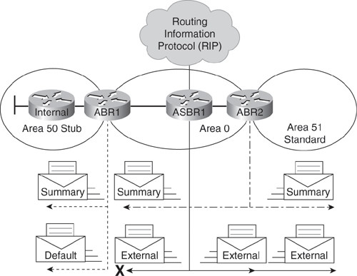
Configuring a stub area reduces the size of the LSDB inside an area, resulting in reduced memory requirements for routers in that area. Routers within the stub area also do not have to run the SPF algorithm as often since they will receive less routing updates. External network LSAs (type 5), such as those redistributed from other routing protocols into OSPF, are not permitted to flood into a stub area, as shown in Figure 5-18. Routing from these areas to a route external to the OSPF autonomous system is based on a default route (0.0.0.0). If a packet is addressed to a network that is not in the routing table of an internal router, the router automatically forwards the packet to the ABR that originates a 0.0.0.0 LSA. Forwarding the packet to the ABR allows routers within the stub area to reduce the size of their routing tables, because a single default route replaces many external routes.
A stub area is typically created using a hub-and-spoke topology, with a spoke being a stub area, such as a branch office. In this case, the branch office does not need to know about every network at the headquarters site, because it can use a default route to reach the networks.
To configure an area as a stub, use the following procedure:
Configure OSPF.
Define an area as stub by adding the area area-id stub router configuration command to all routers within the area.
Table 5-9 describes the parameter of the area stub command.
By default, the ABR of a stubby or totally stubby area advertises a default route with a cost of 1. An option is to change the cost of the default route by using the area area-id default-cost cost router configuration command. The parameters of this command are shown in Table 5-10.
Table 5-10. area default-cost Command Parameters
Parameter | Description |
|---|---|
area-id | The identifier for the stub area, totally stubby area, or NSSA. The identifier can be either a decimal value or a value in dotted-decimal format, like an IP address. |
cost | Cost for the default summary route. The acceptable values are 0 through 16777215. |
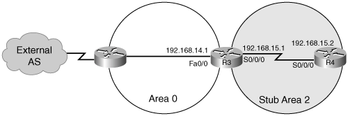
Figure 5-19 illustrates an example. Area 2 is defined as the stub area. No routes from the external autonomous system are forwarded into the stub area.
Example 5-5 shows the OSPF configuration on routers R3 and R4 including enabling an OSPF stub area.
Example 5-5. OSPF Stub Area Configuration for Routers R3 and R4 in Figure 5-19
Router R3:
R3(config)#interface FastEthernet0/0
R3(config-if)#ip address 192.168.14.1 255.255.255.0
R3(config)#interface Serial 0/0/0
R3(config-if)#ip address 192.168.15.1 255.255.255.252
R3(config)#router ospf 100
R3(config-router)#network 192.168.14.0.0 0.0.0.255 area 0
R3(config-router)#network 192.168.15.0.0 0.0.0.255 area 2
R3(config-router)#area 2 stub

Router R4:
R4(config)#interface Serial 0/0/0
R4(config-if)#ip address 192.168.15.2 255.255.255.252

R4(config)#router ospf 100
R4(config-router)#network 192.168.15.0.0 0.0.0.255 area 2
R4(config-router)#area 2 stub
The last line in each configuration (area 2 stub) defines the stub area. The R3 router (the ABR) automatically advertises 0.0.0.0 (the default route) with a default cost metric of 1 into the stub area.
Each router in the stub area must be configured with the area stub command.
The routes that appear in the routing table of router R4 are as follows:
Intra-area routes, which are designated with an O in the routing table
The default route and interarea routes, which are both designated with an IA in the routing table
The default route, which is also denoted with an asterisk (O*IA)
Note
The hello packet exchanged between OSPF routers contains a stub area flag that must match on neighboring routers. The area area-id stub command must be enabled on all routers in the stub area so that they all have the stub flag set; they can then become neighbors and exchange routing information.
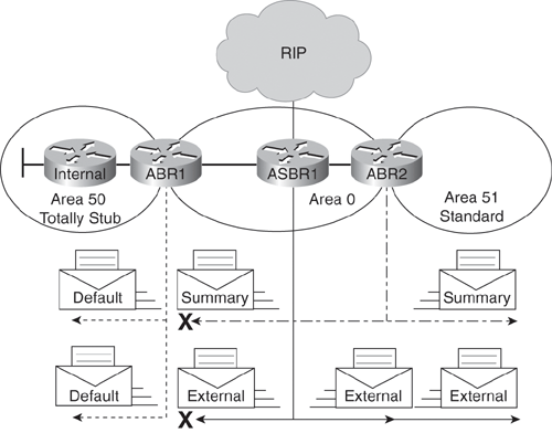
A totally stubby area is a Cisco-specific feature that further reduces the number of routes in the routing table. A totally stubby area blocks external type 5 LSAs and summary type 3 and type 4 LSAs (interarea routes) from entering the area, as shown in Figure 5-20. By blocking these routes, the totally stubby area recognizes only intra-area routes and the default route 0.0.0.0. ABRs inject the default summary link 0.0.0.0 into the totally stubby area. Each router picks the closest ABR as a gateway to everything outside the area.
Totally stubby areas minimize routing information further than stub areas and increase stability and scalability of OSPF internetworks. Using totally stubby areas is typically a better solution than using stub areas, assuming the ABR is a Cisco router.
To configure an area as totally stubby, do the following:
Configure OSPF.
Define an area as totally stubby by adding the area area-id stub router configuration command to all routers in the area.
At the ABR only, add the no-summary parameter to the area area-id stub command.
Table 5-11 explains the area area-id stub no-summary command.
Table 5-11. area area-id stub no-summary Command Parameters
Parameter | Description |
|---|---|
area-id | The identifier for the stub or totally stubby area. It can be either a decimal value or a value in dotted-decimal format, like an IP address. |
no-summary | Stops summary LSAs, in addition to external LSAs, from flooding into the totally stubby area. |
Figure 5-21 shows an example of a totally stubby area topology. The configurations on routers R2, R3, and R4 are shown in Example 5-6. All routes advertised into area 1 (from area 0 and the external autonomous system) default to 0.0.0.0. The default route cost is set to 5 on R2 and to 10 on R4. Both default routes are advertised into area 1. However, the default route from R2 is advertised with a lower cost to make it more preferable if the internal cost from R3 to R4 is the same as the internal cost from R3 to R2.
Example 5-6. Totally Stubby Configuration for Routers in Figure 5-21
Router R2:
R2(config)#router ospf 10
R2(config-router)#network 172.17.0.0 0.0.255.255 area 0
R2(config-router)#network 172.16.0.0 0.0.255.255 area 1
R2(config-router)#area 1 stub no-summary
R2(config-router)#area 1 default-cost 5

Router R3:
R3(config)#router ospf 10
R3(config-router)#network 172.16.0.0 0.0.255.255 area 1
R3(config-router)#area 1 stub

Router R4:
R4(config)#router ospf 10
R4(config-router)#network 172.17.0.0 0.0.255.255 area 0
R4(config-router)#network 172.16.0.0 0.0.255.255 area 1
R4(config-router)#area 1 stub no-summary
R4(config-router)#area 1 default-cost 10
Notice that R3 requires the area 1 stub command, yet the no-summary extension is not required. Only ABRs use no-summary to keep summary LSAs from being propagated into another area.
This section illustrates routing tables when different area types are configured.
Example 5-7 shows how the routing table of an OSPF router in a standard area (without any kind of stub configuration) might look. Intra-area, interarea, and external routes are all maintained in a standard area.
Example 5-7. Routing Table in a Standard Area
P1R3#show ip route
<output omitted>

Gateway of last resort is not set
     172.31.0.0/32 is subnetted, 4 subnets
O IA    172.31.22.4 [110/782] via 10.1.1.1, 00:02:44, FastEthernet0/0
O IA    172.31.11.1 [110/1] via 10.1.1.1, 00:02:44, FastEthernet0/0
O IA    172.31.11.2 [110/782] via 10.1.3.4, 00:02:52, Serial0/0/0
                    [110/782] via 10.1.1.1, 00:02:52, FastEthernet0/0
O IA    172.31.11.4 [110/782] via 10.1.1.1, 00:02:44, FastEthernet0/0
     10.0.0.0/8 is variably subnetted, 7 subnets, 2 masks
O       10.11.0.0/24 [110/782] via 10.1.1.1, 00:03:22, FastEthernet0/0
C       10.200.200.13/32 is directly connected, Loopback0
C       10.1.3.0/24 is directly connected, Serial0/0/0
O       10.1.2.0/24 [110/782] via 10.1.3.4, 00:03:23, Serial0/0/0
C       10.1.1.0/24 is directly connected, FastEthernet0/0
O       10.1.0.0/24 [110/782] via 10.1.1.1, 00:03:23, FastEthernet0/0
O E2    10.254.0.0/24 [110/50] via 10.1.1.1, 00:02:39, FastEthernet0/0
P1R3#
Example 5-8 shows how the same routing table looks if the area is configured as a stub area. Intra-area and interarea routes are all maintained. However, external routes are not visible in the routing table; they are accessible via the intra-area default route.
Example 5-8. Routing Table in a Stub Area
P1R3#show ip route
<output omitted>

Gateway of last resort is 10.1.1.1 to network 0.0.0.0
     172.31.0.0/32 is subnetted, 4 subnets
O IA    172.31.22.4 [110/782] via 10.1.1.1, 00:01:49, FastEthernet0/0
O IA    172.31.11.1 [110/1] via 10.1.1.1, 00:01:49, FastEthernet0/0
O IA    172.31.11.2 [110/782] via 10.1.3.4, 00:01:49, Serial0/0/0
                    [110/782] via 10.1.1.1, 00:01:49, FastEthernet0/0
O IA    172.31.11.4 [110/782] via 10.1.1.1, 00:01:49, FastEthernet0/0
     10.0.0.0/8 is variably subnetted, 6 subnets, 2 masks
O       10.11.0.0/24 [110/782] via 10.1.1.1, 00:01:50, FastEthernet0/0
C       10.200.200.13/32 is directly connected, Loopback0
C       10.1.3.0/24 is directly connected, Serial0/0/0
O       10.1.2.0/24 [110/782] via 10.1.3.4, 00:01:50, Serial0/0/0
C       10.1.1.0/24 is directly connected, FastEthernet0/0
O       10.1.0.0/24 [110/782] via 10.1.1.1, 00:01:50, FastEthernet0/0
O*IA 0.0.0.0/0 [110/2] via 10.1.1.1, 00:01:51, FastEthernet0/0
P1R3#
Example 5-9 shows how the same routing table looks if summarization is performed on the ABR; the area is still configured as a stub area. Intra-area and summarized interarea routes are all maintained. External routes are not visible in the routing table but are accessible via the intra-area default route.
Example 5-9. Routing Table in a Stub Area with Summarization
P1R3#show ip route
<output omitted>

Gateway of last resort is 10.1.1.1 to network 0.0.0.0
     172.31.0.0/16 is variably subnetted, 2 subnets, 2 masks
O IA    172.31.22.4/32 [110/782] via 10.1.1.1, 00:13:08, FastEthernet0/0
O IA    172.31.11.0/24 [110/1] via 10.1.1.1, 00:02:39, FastEthernet0/0
     10.0.0.0/8 is variably subnetted, 6 subnets, 2 masks
O       10.11.0.0/24 [110/782] via 10.1.1.1, 00:13:08, FastEthernet0/0
C       10.200.200.13/32 is directly connected, Loopback0
C       10.1.3.0/24 is directly connected, Serial0/0/0
O       10.1.2.0/24 [110/782] via 10.1.3.4, 00:13:09, Serial0/0/0
C       10.1.1.0/24 is directly connected, FastEthernet0/0
O       10.1.0.0/24 [110/782] via 10.1.1.1, 00:13:09, FastEthernet0/0
O*IA 0.0.0.0/0 [110/2] via 10.1.1.1, 00:13:09, FastEthernet0/0
P1R3#
Example 5-10 shows how the same routing table looks if the area is configured as a totally stubby area. Notice that routers in the totally stubby area have the smallest routing tables. Intra-area routes are maintained. Interarea and external routes are not visible in the routing table but are accessible via the intra-area default route.
Example 5-10. Routing Table in a Totally Stubby Area
P1R3#show ip route
<output omitted>

Gateway of last resort is 10.1.1.1 to network 0.0.0.0
     10.0.0.0/8 is variably subnetted, 6 subnets, 2 masks
O       10.11.0.0/24 [110/782] via 10.1.1.1, 00:16:53, FastEthernet0/0
C       10.200.200.13/32 is directly connected, Loopback0
C       10.1.3.0/24 is directly connected, Serial0/0/0
O       10.1.2.0/24 [110/782] via 10.1.3.4, 00:16:53, Serial0/0/0
C       10.1.1.0/24 is directly connected, FastEthernet0/0
O       10.1.0.0/24 [110/782] via 10.1.1.1, 00:16:53, FastEthernet0/0
O*IA 0.0.0.0/0 [110/2] via 10.1.1.1, 00:00:48, FastEthernet0/0
P1R3#
The OSPF NSSA feature is described by RFC 3101 and was introduced in Cisco IOS Software Release 11.2. It is a nonproprietary extension of the existing stub area feature that allows the injection of external routes in a limited fashion into the stub area.
Redistribution into an NSSA area creates a special type of LSA known as type 7, which can exist only in an NSSA area. An NSSA ASBR generates this LSA, and an NSSA ABR translates it into a type 5 LSA, which gets propagated into the OSPF domain.
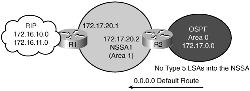
The NSSA feature allows an area to retain the other stub area features—the ABR sends a default route into the NSSA instead of external routes from other ASBRs—while also allowing an ASBR to be inside of the area. Recall that one of the rules of stub areas is that there must not be an ASBR inside of a stub area; an NSSA—a not-so-stubby area—bends this rule. Figure 5-22 illustrates an NSSA.
The type 7 LSA is described in the routing table as an O N2 or O N1 (N means NSSA). N1 means that the metric is calculated like external type 1; N2 means that the metric is calculated like external type 2. The default is O N2.
To configure an NSSA, the area area-id nssa [no-redistribution] [default-information-originate] [metric metric-value] [metric-type type-value] [no-summary] router configuration command is used in place of the area area-id stub command. Remember that all routers in the NSSA must have this command configured; two routers will not form an adjacency unless both are configured as NSSA.
Table 5-12 defines the parameters of the area nssa command.
Table 5-12. area area-id nssa Command Parameters
Parameter | Description |
|---|---|
area-id | The identifier for the NSSA. It can be either a decimal value or a value in dotted-decimal format, like an IP address. |
no-redistribution | (Optional) Used when the router is an NSSA ABR and you want the redistribute command to import routes only into the standard areas, but not into the NSSA area. |
default-information-originate | (Optional) Used to generate a type 7 default LSA into the NSSA area. This keyword takes effect only on an NSSA ABR or an NSSA ASBR. |
metric metric-value | (Optional) Metric that is used for generating the default route. Acceptable values are 0 through 16777214. |
metric-type type-value | (Optional) OSPF metric type for default routes. It can be one of the following values: 1: type 1 external route 2: type 2 external route |
no-summary | (Optional) Allows an area to be an NSSA but not have summary routes injected into it. Thus, the area is a totally stubby NSSA. |
In Figure 5-23 and Example 5-11, R1 is the ASBR that redistributes RIP routes into area 1, the NSSA. R2 is the NSSA ABR; this router converts type 7 LSAs into type 5 LSAs for advertisement into backbone area 0. R2 is also configured to summarize the type 5 LSAs that originate from the RIP network; the 172.16.0.0 subnets are summarized to 172.16.0.0/16 and are advertised into area 0. To cause R2 (the NSSA ABR) to generate an O*N2 default route (O*N2 0.0.0.0/0) into the NSSA, the default-information-originate parameter is used on the area area-id nssa command on R2.
Example 5-11. OSPF NSSA Configuration for Routers in Figure 5-23
Router R1:
R1(config)#router ospf 10
R1(config-router)#redistribute rip subnets
R1(config-router)#default metric 150
R1(config-router)#network 172.17.0.0 0.0.255.255 area 1
R1(config-router)#area 1 nssa

Router R2:
R2(config)#router ospf 10
R2(config-router)#summary-address 172.16.0.0 255.255.0.0
R2(config-router)#network 172.17.20.0 0.0.0.255 area 1
R2(config-router)#network 172.17.0.0 0.0.255.255 area 0
R2(config-router)#area 1 nssa default-information-originate
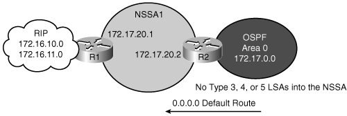
In another example in Figure 5-24 and Example 5-12, notice that the ABR is using the area 1 nssa no-summary command. This command works exactly the same as the totally stubby technique. A single default route replaces both inbound external (type 5) LSAs and summary (type 3 and 4) LSAs into the area. The NSSA ABR, which is R2, automatically generates the O*N2 default route into the NSSA area when the no-summary option is configured at the ABR, so the default-information-originate parameter is not required.
Example 5-12. NSSA Totally Stubby Configuration for Routers in Figure 5-24
Router R1:
R1(config)#router ospf 10
R1(config-router)#redistribute rip subnets
R1(config-router)#default metric 150
R1(config-router)#network 172.17.0.0 0.0.255.255 area 1
R1(config-router)#area 1 nssa

Router R2:
R2(config)#router ospf 10
R2(config-router)#summary-address 172.16.0.0 255.255.0.0
R2(config-router)#network 172.17.20.0 0.0.0.255 area 1
R2(config-router)#network 172.17.0.0 0.0.255.255 area 0
R2(config-router)#area 1 nssa no-summary
All other routers in the NSSA area require the area 1 nssa command only. The NSSA totally stubby configuration is a Cisco-specific feature, just as the totally stubby area feature is.
The show commands in Table 5-13 are used to display which area type has been configured and other information about the area.
Table 5-13. show Commands for All Area Types
Command | Description |
|---|---|
show ip ospf | Displays OSPF information, including which areas are standard, stub, or NSSA |
show ip ospf database | Displays details of LSAs |
show ip ospf database nssa-external | Displays specific details of each LSA type 7 update in the database |
show ip route | Displays all routes |
OSPF’s two-tiered area hierarchy requires that all areas be directly connected to the backbone area, area 0, and that area 0 be contiguous.
A virtual link is a link that allows discontiguous area 0s to be connected, or a disconnected area to be connected to area 0, via a transit area. The OSPF virtual link feature should be used only in very specific cases, for temporary connections or backup after a failure. Virtual links should not be used as a primary backbone design feature.
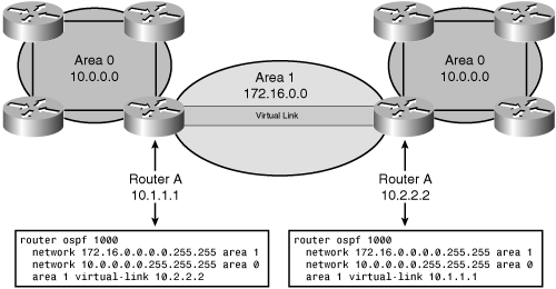
Virtual links are part of the OSPF open standard and have been a part of Cisco IOS Software since software release 10.0. In Figure 5-25, area 0 is discontiguous because of a network failure. A logical link (virtual link) is built between the two ABRs, routers A and B. This virtual link is similar to a standard OSPF adjacency; however, in a virtual link, the routers do not have to be directly attached to neighboring routers.
The Hello protocol works over virtual links as it does over standard links, in 10-second intervals. However, LSA updates work differently on virtual links. An LSA usually refreshes every 30 minutes; LSAs learned through a virtual link have the DoNotAge (DNA) option set, so that the LSA does not age out. This DNA technique is required to prevent excessive flooding over the virtual link.
Use the area area-id virtual-link router-id [authentication [message-digest | null]] [hello-interval seconds] [retransmit-interval seconds] [transmit-delay seconds] [dead-interval seconds] [[authentication-key key] | [message-digest-key key-id md5 key]] router configuration command to define an OSPF virtual link. To remove a virtual link, use the no form of this command.
Table 5-14 describes the options available with the area area-id virtual-link command. Make sure you understand the effect of these options before changing them. For instance, the smaller the hello interval, the faster the detection of topological changes; however, more routing traffic ensues.
You should be conservative with the setting of the retransmit interval, or the result is needless retransmissions; the value is larger for serial lines and virtual links. The transmit delay value should take into account the interface’s transmission and propagation delays.
Table 5-14. area area-id virtual-link Command Parameters
Parameter | Description |
|---|---|
area-id | Specifies the area ID of the transit area for the virtual link. This ID can be either a decimal value or in dotted-decimal format, like a valid IP address. There is no default. The transit area cannot be a stub area. |
router-id | Specifies the router ID of the virtual link neighbor. The router ID appears in the show ip ospf display. This value is in an IP address format. There is no default. |
authentication | (Optional) Specifies an authentication type. |
message-digest | (Optional) Specifies the use of message digest 5 (MD5) authentication. |
null | (Optional) Overrides simple password or MD5 authentication if configured for the area; no authentication is used. |
hello-interval seconds | (Optional) Specifies the time (in seconds) between the hello packets that the Cisco IOS Software sends on an interface. The unsigned integer value is advertised in the hello packets. The value must be the same for all routers and access servers attached to a common network. The default is 10 seconds. |
retransmit-interval seconds | (Optional) Specifies the time (in seconds) between LSA retransmissions for adjacencies belonging to the interface. The value must be greater than the expected round-trip delay between any two routers on the attached network. The default is 5 seconds. |
transmit-delay seconds | (Optional) Specifies the estimated time (in seconds) to send an LSU packet on the interface. This integer value must be greater than 0. LSAs in the update packet have their age incremented by this amount before transmission. The default value is 1 second. |
dead-interval seconds | (Optional) Specifies the time (in seconds) that must pass without hello packets being seen before a neighboring router declares the router down. This is an unsigned integer value. The default is four times the default hello interval, or 40 seconds. As with the hello interval, this value must be the same for all routers and access servers attached to a common network. |
authentication-key key | (Optional) Specifies the password used by neighboring routers for simple password authentication. It is any continuous string of up to 8 characters. There is no default value. |
message-digest-key key-id md5 key | (Optional) Identifies the key ID and key (password) used between this router and neighboring routers for MD5 authentication. There is no default value. |
Note
OSPF authentication, including details of the key and key-id parameters, is described further in the “Configuring OSPF Authentication” section later in this chapter.
The area area-id virtual-link command requires the router ID of the far-end router. To find the router ID of the far-end router, use the show ip ospf command, show ip ospf interface command, or show ip protocol command on that remote router.
Example 5-13 illustrates the output of the show ip ospf command, displaying the OSPF router ID.
Example 5-13. Finding the OSPF Router ID for Use on a Virtual Link
remoterouter#show ip ospf
 Routing Process "ospf 1000" with ID 10.2.2.2
 Supports only single TOS(TOS0) routes
 Supports opaque LSA
 Supports Link-local Signaling (LLS)
 Supports area transit capability
 It is an area border router
<output omitted>
In the example in Figure 5-26, area 0 is discontiguous (split into two pieces) because of network failure. A virtual link is used as a backup strategy to temporarily reconnect area 0; area 1 is used as the transit area. Router A builds a virtual link to router B, and router B builds a virtual link to the router A. Each router points at the other router’s router ID.
The show ip ospf virtual-links command is used to verify OSPF virtual link operation. Example 5-14 provides the output of the show ip ospf virtual-links command on router A in the example in Figure 5-26, verifying that the configured link works properly.
Example 5-14. show ip ospf virtual-links Command Output from Router A in Figure 5-26
RouterA#show ip ospf virtual-links
Virtual Link OSPF_VL0 to router 10.2.2.2 is up
  Run as demand circuit
  DoNotAge LSA allowed.
  Transit area 1, via interface Serial0/0/1, Cost of using 781
  Transmit Delay is 1 sec, State POINT_TO_POINT,
  Timer intervals configured, Hello 10, Dead 40, Wait 40, Retransmit 5
    Hello due in 00:00:07
    Adjacency State FULL (Hello suppressed)
    Index 1/2, retransmission queue length 0, number of retransmission 1
    First 0x0(0)/0x0(0) Next 0x0(0)/0x0(0)
    Last retransmission scan length is 1, maximum is 1
    Last retransmission scan time is 0 msec, maximum is 0 msec
RouterA#
Table 5-15 describes some of the fields of the output of the show ip ospf virtual-links command in detail.
Table 5-15. show ip ospf virtual-links Command Fields
Field | Description |
|---|---|
Virtual Link OSPF_VL0 to router 10.2.2.2 is up | Specifies the OSPF neighbor and whether the link to that neighbor is up or down |
Transit area 1 | Specifies the transit area through which the virtual link is formed |
Via interface Serial0/0/1 | Specifies the interface through which the virtual link is formed |
Cost of using 781 | Specifies the cost of reaching the OSPF neighbor through the virtual link |
Transmit Delay is 1 sec | Specifies the transmit delay on the virtual link |
State POINT_TO_POINT | Specifies the state of the OSPF neighbor |
Timer intervals configured | Specifies the various timer intervals configured for the link |
Hello due in 0:00:07 | Specifies when the next hello is expected from the neighbor |
Adjacency State FULL | Specifies the adjacency state between the neighbors |
Routers across a virtual link become adjacent and exchange LSAs via the virtual link, similar to the process over a physical link.
Other commands that are useful when troubleshooting virtual links are show ip ospf neighbor, show ip ospf database, and debug ip ospf adj.
Example output from the show ip ospf neighbor command is provided in Example 5-15.
Example 5-15. show ip ospf neighbor Command Output from Router A in Figure 5-26
RouterA#show ip ospf neighbor

Neighbor ID     Pri   State       Dead Time   Address      Interface
10.200.200.13     1   FULL/DR     00:00:33    10.1.1.3     FastEthernet0/0
10.2.2.2          0   FULL/  -       -        172.16.1.2   OSPF_VL0
10.2.2.2          0   FULL/  -    00:00:32    172.16.1.2   Serial0/0/1
RouterA#
Example output from the show ip ospf database command is shown in Example 5-16.
Example 5-16. show ip ospf database Command Output from Router A in Figure 5-26
RouterA#show ip ospf database router 10.2.2.2

            OSPF Router with ID (10.1.1.1) (Process ID 1000)

                Router Link States (Area 0)

  Routing Bit Set on this LSA
  LS age: 1 (DoNotAge)
  Options: (No TOS-capability, DC)
  LS Type: Router Links
  Link State ID: 10.2.2.2
  Advertising Router: 10.2.2.2
  LS Seq Number: 80000003
  Checksum: 0x8380
  Length: 48
  Area Border Router
  Number of Links: 2

    Link connected to: a Virtual Link
     (Link ID) Neighboring Router ID: 10.1.1.1
     (Link Data) Router Interface address: 172.16.1.2
      Number of TOS metrics: 0
       TOS 0 Metrics: 781
    Link connected to: a Transit Network
     (Link ID) Designated Router address: 10.1.2.2
     (Link Data) Router Interface address: 10.1.2.2
      Number of TOS metrics: 0
       TOS 0 Metrics: 1

                Router Link States (Area 1)

  Routing Bit Set on this LSA
  LS age: 1688
  Options: (No TOS-capability, DC)
  LS Type: Router Links
  Link State ID: 10.2.2.2
  Advertising Router: 10.2.2.2
  LS Seq Number: 80000008
  Checksum: 0xCC81
  Length: 48
  Area Border Router
  Virtual Link Endpoint
  Number of Links: 2

    Link connected to: another Router (point-to-point)
     (Link ID) Neighboring Router ID: 10.1.1.1
     (Link Data) Router Interface address: 172.16.1.2
      Number of TOS metrics: 0
       TOS 0 Metrics: 781

    Link connected to: a Stub Network
     (Link ID) Network/subnet number: 172.16.1.0
     (Link Data) Network Mask: 255.255.255.0
      Number of TOS metrics: 0
       TOS 0 Metrics: 781

RouterA#
You can prevent your router from receiving fraudulent route updates by configuring neighbor router authentication. OSPF neighbor authentication (also called neighbor router authentication or route authentication) can be configured such that routers can participate in routing based on predefined passwords.
This section describes the types of OSPF authentication and how to configure and troubleshoot them.
Recall that when neighbor authentication has been configured on a router, the router authenticates the source of each routing update packet that it receives. This is accomplished by the exchange of an authenticating key (sometimes referred to as a password) that is known to both the sending and the receiving router.
By default, OSPF uses null authentication, which means that routing exchanges over a network are not authenticated. OSPF supports two other authentication methods: simple password authentication (also called plain text authentication), and MD5 authentication.
OSPF MD5 authentication includes a nondecreasing sequence number in each OSPF packet to protect against replay attacks.
To configure OSPF simple password authentication, complete the following steps:
Assign a password to be used when using OSPF simple password authentication with neighboring routers, using the ip ospf authentication-key password interface configuration command. Table 5-16 describes the parameter of the ip ospf authentication-key command.
Note
In Cisco IOS Release 12.4, the router will give a warning message if you try to configure a password longer than eight characters; only the first eight characters will be used. Some earlier Cisco IOS releases did not provide this warning.
The password created by this command is used as a “key” that is inserted directly into the OSPF header when the Cisco IOS Software originates routing protocol packets. A separate password can be assigned to each network on a per-interface basis. All neighboring routers on the same network must have the same password to be able to exchange OSPF information.
Note
If the service password-encryption command is not used when configuring OSPF authentication, the password will be stored as plain text in the router configuration. If you configure the service password-encryption command, the password will be stored and displayed in an encrypted form; when it is displayed, there will be an encryption type of 7 specified before the encrypted password.
Specify the authentication type using the ip ospf authentication [message-digest | null] interface configuration command. Table 5-17 describes the parameters of the ip ospf authentication command.
For simple password authentication, use the ip ospf authentication command with no parameters. Before using this command, configure a password for the interface using the ip ospf authentication-key command.
The ip ospf authentication command was introduced in Cisco IOS Software Release 12.0. For backward compatibility, authentication type for an area is still supported. If the authentication type is not specified for an interface, the authentication type for the area will be used (the area default is null authentication). To enable authentication for an OSPF area, use the area area-id authentication [message-digest] router configuration command. Table 5-18 describes the parameters of the area authentication command.
Table 5-18. area authentication Command Parameters
Parameter
Description
area-id
Identifier of the area for which authentication is to be enabled. The identifier can be specified as either a decimal value or an IP address.
message-digest
(Optional) Enables MD5 authentication for the area specified by the area-id argument.
For simple password authentication, use the area authentication command with no parameters.
Figure 5-27 shows the network used to illustrate the configuration, verification, and troubleshooting of simple password authentication. The configuration of the R1 and R2 routers are shown in Example 5-17.
Example 5-17. Configuration of Routers R1 and R2 in Figure 5-27
Router R1:
<output omitted>
interface Loopback0
 ip address 10.1.1.1 255.255.255.0

<output omitted>
interface Serial0/0/1
 ip address 192.168.1.101 255.255.255.224
 ip ospf authentication
 ip ospf authentication-key plainpas

<output omitted>
router ospf 10
 log-adjacency-changes
 network 10.1.1.1 0.0.0.0 area 0
 network 192.168.1.0 0.0.0.255 area 0

Router R2:
<output omitted>
interface Loopback0
 ip address 10.2.2.2 255.255.255.0

<output omitted>
interface Serial0/0/1
 ip address 192.168.1.102 255.255.255.224
 ip ospf authentication
 ip ospf authentication-key plainpas

<output omitted>
router ospf 10
 log-adjacency-changes
 network 10.2.2.2 0.0.0.0 area 0
 network 192.168.1.0 0.0.0.255 area 0
Notice that the connecting interfaces on both R1 and R2 are configured for the same type of authentication with the same authentication key. Simple password authentication is configured on interface serial 0/0/1 on both routers, with the ip ospf authentication command. The interfaces are configured with an authentication key of plainpas.
Example 5-18 shows the output of the show ip ospf neighbor and show ip route commands on the R1 router in Figure 5-27. The results of a ping to the R2 loopback interface address are also displayed to illustrate that the link is working.
Example 5-18. Verifying Simple Password Authentication on R1 in Figure 5-27
R1#show ip ospf neighbor
Neighbor ID     Pri   State           Dead Time   Address        Interface
10.2.2.2          0   FULL/  -        00:00:32    192.168.1.102  Serial0/0/1

R1#show ip route
<output omitted>
Gateway of last resort is not set
     10.0.0.0/8 is variably subnetted, 2 subnets, 2 masks
O       10.2.2.2/32 [110/782] via 192.168.1.102, 00:01:17, Serial0/0/1
C       10.1.1.0/24 is directly connected, Loopback0
     192.168.1.0/27 is subnetted, 1 subnets
C      192.168.1.96 is directly connected, Serial0/0/1

R1#ping 10.2.2.2
Type escape sequence to abort.
Sending 5, 100-byte ICMP Echos to 10.2.2.2, timeout is 2 seconds:
!!!!!
Success rate is 100 percent (5/5), round-trip min/avg/max = 28/29/32 ms
Notice in the show ip ospf neighbor command output that the neighbor state is FULL, indicating that the two routers have successfully formed an OSPF adjacency. The routing table verifies that the 10.2.2.2 address has been learned via OSPF over the serial connection.
The debug ip ospf adj command is used to display OSPF adjacency-related events and is useful when troubleshooting authentication.
The output of the debug ip ospf adj command in Example 5-19 illustrates successful communication on the R1 router in Figure 5-27 after the serial 0/0/1 interface, on which simple password authentication has been configured, comes up.
Note
Although this debug ip ospf adj output does not indicate anything about the authentication, it does show that the two routers successfully form a FULL adjacency. As the output in the next section illustrates, this command output does display authentication failures if there are any. During testing we were unable to find any debug command output that displayed information about successful OSPF simple password authentication.
Example 5-19. Successful: Simple Password Authentication on R1 in Figure 5-27
*Apr 20 18:41:51.242: OSPF: Interface Serial0/0/1 going Up
*Apr 20 18:41:51.742: OSPF: Build router LSA for area 0, router ID 10.1.1.1, seq 0x80000013
*Apr 20 18:41:52.242: %LINEPROTO-5-UPDOWN: Line protocol on Interface Serial0/0/1, changed
   state to up
*Apr 20 18:42:01.250: OSPF: 2 Way Communication to 10.2.2.2 on Serial0/0/1, state 2WAY
*Apr 20 18:42:01.250: OSPF: Send DBD to 10.2.2.2 on Serial0/0/1 seq 0x9B6 opt 0x52 flag
   0x7 len 32
*Apr 20 18:42:01.262: OSPF: Rcv DBD from 10.2.2.2 on Serial0/0/1 seq 0x23ED opt0x52 flag
   0x7 len 32  mtu 1500 state EXSTART
*Apr 20 18:42:01.262: OSPF: NBR Negotiation Done. We are the SLAVE
*Apr 20 18:42:01.262: OSPF: Send DBD to 10.2.2.2 on Serial0/0/1 seq 0x23ED opt 0x52 flag
   0x2 len 72
*Apr 20 18:42:01.294: OSPF: Rcv DBD from 10.2.2.2 on Serial0/0/1 seq 0x23EE opt0x52 flag
   0x3 len 72  mtu 1500 state EXCHANGE
*Apr 20 18:42:01.294: OSPF: Send DBD to 10.2.2.2 on Serial0/0/1 seq 0x23EE opt 0x52 flag
   0x0 len 32
*Apr 20 18:42:01.294: OSPF: Database request to 10.2.2.2
*Apr 20 18:42:01.294: OSPF: sent LS REQ packet to 192.168.1.102, length 12
*Apr 20 18:42:01.314: OSPF: Rcv DBD from 10.2.2.2 on Serial0/0/1 seq 0x23EF opt0x52 flag
   0x1 len 32  mtu 1500 state EXCHANGE
*Apr 20 18:42:01.314: OSPF: Exchange Done with 10.2.2.2 on Serial0/0/1
*Apr 20 18:42:01.314: OSPF: Send DBD to 10.2.2.2 on Serial0/0/1 seq 0x23EF opt 0x52 flag
   0x0 len 32
*Apr 20 18:42:01.326: OSPF: Synchronized with 10.2.2.2 on Serial0/0/1, state FULL
*Apr 20 18:42:01.330: %OSPF-5-ADJCHG: Process 10, Nbr 10.2.2.2 on Serial0/0/1 from LOADING
   to FULL, Loading Done
*Apr 20 18:42:01.830: OSPF: Build router LSA for area 0, router ID 10.1.1.1, seq 0x80000014
The output of the show ip ospf neighbor command shown in Example 5-20 illustrates that R1 has successfully formed an adjacency with R2.
Example 5-20. R1 and R2 in Figure 5-27 Have Formed an Adjacency
R1#show ip ospf neighbor
Neighbor ID     Pri   State           Dead Time   Address        Interface
10.2.2.2          0   FULL/  -        00:00:34    192.168.1.102  Serial0/0/1
Using the network in Figure 5-27, if simple password authentication is configured on the R1 serial 0/0/1 interface but no authentication is configured on the R2 serial 0/0/1 interface, the routers will not be able to form an adjacency over that link. The output of the debug ip ospf adj command shown in Example 5-21 illustrates that the routers report a mismatch in authentication type; no OSPF packets will be sent between the neighbors.
Example 5-21. Simple Password Authentication on R1 and no Authentication on R2 in Figure 5-27
R1#
*Apr 17 18:51:31.242: OSPF: Rcv pkt from 192.168.1.102, Serial0/0/1 : Mismatch
   Authentication type. Input packet specified type 0, we use type 1

R2#
*Apr 17 18:50:43.046: OSPF: Rcv pkt from 192.168.1.101, Serial0/0/1 : Mismatch
   Authentication type. Input packet specified type 1, we use type 0
Note
The different types of OSPF authentication have the following type codes:
Null—. Type 0
Simple password—. Type 1
MD5—. Type 2
If simple password authentication is configured on the R1 serial 0/0/1 interface and on the R2 serial 0/0/1 interface, but with different passwords, the routers will not be able to form an adjacency over that link. The outputs of the debug ip ospf adj command shown in Example 5-22 illustrate that the routers report a mismatch in authentication key; no OSPF packets will be sent between the neighbors.
Example 5-22. Simple Password Authentication on R1 and R2 in Figure 5-27, but with Different Passwords
R1#
*Apr 17 18:54:01.238: OSPF: Rcv pkt from 192.168.1.102, Serial0/0/1 : Mismatch
   Authentication Key - Clear Text

R2#
*Apr 17 18:53:13.050: OSPF: Rcv pkt from 192.168.1.101, Serial0/0/1 : Mismatch
   Authentication Key - Clear Text
With OSPF MD5 authentication, a key and key ID are configured on each router. To configure OSPF MD5 authentication, complete the following steps:
Assign a key ID and key to be used with neighboring routers that are using the OSPF MD5 authentication, using the ip ospf message-digest-key key-id md5 key interface configuration command. Table 5-19 describes the parameters in the ip ospf message-digest-key command.
The key and the key ID specified in this command are used to generate a message digest (also called a hash) of each OSPF packet; the message digest is appended to the packet. A separate password can be assigned to each network on a per-interface basis.
Usually, one key per interface is used to generate authentication information when sending packets and to authenticate incoming packets. All neighboring routers on the same network must have the same password to be able to exchange OSPF information; in other words, the same key-id on the neighbor router must have the same key value.
The key-id allows for uninterrupted transitions between keys, which is helpful for administrators who want to change the OSPF password without disrupting communication. If an interface is configured with a new key, the router will send multiple copies of the same packet, each authenticated by different keys. The router will stop sending duplicate packets when it detects that all of its neighbors have adopted the new key.
The process of changing keys is as follows. Suppose the current configuration is as follows:
interface FastEthernet 0/0
 ip ospf message-digest-key 100 md5 OLD
The following configuration is then added:
interface FastEthernet 0/0
 ip ospf message-digest-key 101 md5 NEW
The router assumes its neighbors do not have the new key yet, so it begins a rollover process. It sends multiple copies of the same packet, each authenticated by different keys. In this example, the router sends out two copies of the same packet: the first one authenticated by key 100 and the second one authenticated by key 101.
Rollover allows neighboring routers to continue communication while the network administrator is updating them with the new key. Rollover stops once the local system finds that all its neighbors know the new key. The system detects that a neighbor has the new key when it receives packets from the neighbor authenticated by the new key.
After all neighbors have been updated with the new key, the old key should be removed. In this example, you would enter the following:
interface FastEthernet 0/0
 no ip ospf message-digest-key 100
From then on, only key 101 is used for authentication on interface FastEthernet 0/0.
Cisco recommends that you not keep more than one key per interface. Every time you add a new key, you should remove the old key to prevent the local router from continuing to communicate with a hostile system that knows the old key.
Note
If the service password-encryption command is not used when implementing OSPF authentication, the key will be stored as plain text in the router configuration. If you configure the service password-encryption command, the key will be stored and displayed in an encrypted form; when it is displayed, there will be an encryption-type of 7 specified before the encrypted key.
Specify the authentication type using the ip ospf authentication [message-digest | null] interface configuration command. The parameters for this command are as described in the earlier “Configuring Simple Password Authentication” section. For MD5 authentication, use the ip ospf authentication command with the message-digest parameter. Before using this command, configure the message digest key for the interface with the ip ospf message-digest-key command.
Recall that the ip ospf authentication command was introduced in Cisco IOS Software Release 12.0. As for simple password authentication, the MD5 authentication type for an area is still supported using the area area-id authentication message-digest router configuration command, for backward compatibility.
Figure 5-28 shows the network used to illustrate the configuration, verification, and troubleshooting of MD5 authentication. The configuration of the R1 and R2 routers are shown in Example 5-23.
Example 5-23. Configuration of Routers R1 and R2 in Figure 5-28
Router R1:
<output omitted>
interface Loopback0
 ip address 10.1.1.1 255.255.255.0

<output omitted>
interface Serial0/0/1
 ip address 192.168.1.101 255.255.255.224
 ip ospf authentication message-digest
 ip ospf message-digest-key 1 md5 secretpass

<output omitted>
router ospf 10
 log-adjacency-changes
 network 10.1.1.1 0.0.0.0 area 0
 network 192.168.1.0 0.0.0.255 area 0

Router R2:
<output omitted>
interface Loopback0
 ip address 10.2.2.2 255.255.255.0

<output omitted>
interface Serial0/0/1
 ip address 192.168.1.102 255.255.255.224
 ip ospf authentication message-digest
 ip ospf message-digest-key 1 md5 secretpass

<output omitted>
router ospf 10
 log-adjacency-changes
 network 10.2.2.2 0.0.0.0 area 0
 network 192.168.1.0 0.0.0.255 area 0
Notice that the connecting interfaces on both R1 and R2 are configured for the same type of authentication with the same authentication key and key-id. MD5 authentication is configured on interface serial 0/0/1 on both routers with the ip ospf authentication message-digest command. The interfaces on both routers are configured with an authentication key number 1 set to secretpass.
Example 5-24 shows the output of the show ip ospf neighbor and show ip route commands on the R1 router in Figure 5-28. The results of a ping to the R2 loopback interface address is also displayed to illustrate that the link is working.
Example 5-24. Verifying MD5 Authentication on R1 in Figure 5-28
R1#show ip ospf neighbor
Neighbor ID     Pri   State           Dead Time   Address        Interface
10.2.2.2          0   FULL/  -        00:00:31    192.168.1.102  Serial0/0/1

R1#show ip route
<output omitted>
Gateway of last resort is not set
      10.0.0.0/8 is variably subnetted, 2 subnets, 2 masks
O       10.2.2.2/32 [110/782] via 192.168.1.102, 00:00:37, Serial0/0/1
C       10.1.1.0/24 is directly connected, Loopback0
     192.168.1.0/27 is subnetted, 1 subnets
C       192.168.1.96 is directly connected, Serial0/0/1

R1#ping 10.2.2.2
Type escape sequence to abort.
Sending 5, 100-byte ICMP Echos to 10.2.2.2, timeout is 2 seconds:
!!!!!
Success rate is 100 percent (5/5), round-trip min/avg/max = 28/28/32 ms
Notice in the show ip ospf neighbor command output that that the neighbor state is FULL, indicating that the two routers have successfully formed an OSPF adjacency. The routing table verifies that the 10.2.2.2 address has been learned via OSPF over the serial connection.
As for simple password authentication, the debug ip ospf adj command is used to display OSPF adjacency-related events and is very useful when troubleshooting MD5 authentication.
The output of the debug ip ospf adj command in Example 5-25 illustrates successful MD5 authentication on the R1 router in Figure 5-28 after the serial 0/0/1 interface, on which authentication has been configured, comes up.
Example 5-25. Successful MD5 Authentication on R1 in Figure 5-28
R1#debug ip ospf adj
OSPF adjacency events debugging is on
*Apr 20 17:13:56.530: %LINK-3-UPDOWN: Interface Serial0/0/1, changed state to up
*Apr 20 17:13:56.530: OSPF: Interface Serial0/0/1 going Up
*Apr 20 17:13:56.530: OSPF: Send with youngest Key 1
*Apr 20 17:13:57.030: OSPF: Build router LSA for area 0, router ID 10.1.1.1, seq 0x80000009
*Apr 20 17:13:57.530: %LINEPROTO-5-UPDOWN: Line protocol on Interface Serial0/0/1, changed
   state to up
*Apr 20 17:14:06.530: OSPF: Send with youngest Key 1
*Apr 20 17:14:06.546: OSPF: 2 Way Communication to 10.2.2.2 on Serial0/0/1, state 2WAY
*Apr 20 17:14:06.546: OSPF: Send DBD to 10.2.2.2 on Serial0/0/1 seq 0xB37 opt 0x52 flag
   0x7 len 32
*Apr 20 17:14:06.546: OSPF: Send with youngest Key 1
*Apr 20 17:14:06.562: OSPF: Rcv DBD from 10.2.2.2 on Serial0/0/1 seq 0x32F opt 0
x52 flag 0x7 len 32  mtu 1500 state EXSTART
*Apr 20 17:14:06.562: OSPF: NBR Negotiation Done. We are the SLAVE
*Apr 20 17:14:06.562: OSPF: Send DBD to 10.2.2.2 on Serial0/0/1 seq 0x32F opt 0x52 flag
   0x2 len 72
*Apr 20 17:14:06.562: OSPF: Send with youngest Key 1
*Apr 20 17:14:06.602: OSPF: Rcv DBD from 10.2.2.2 on Serial0/0/1 seq 0x330 opt 0x52 flag
0x3 len 72  mtu 1500 state EXCHANGE
*Apr 20 17:14:06.602: OSPF: Send DBD to 10.2.2.2 on Serial0/0/1 seq 0x330 opt 0x52 flag
   0x0 len 32
*Apr 20 17:14:06.602: OSPF: Send with youngest Key 1
*Apr 20 17:14:06.602: OSPF: Database request to 10.2.2.2
*Apr 20 17:14:06.602: OSPF: Send with youngest Key 1
*Apr 20 17:14:06.602: OSPF: sent LS REQ packet to 192.168.1.102, length 12
*Apr 20 17:14:06.614: OSPF: Send with youngest Key 1
*Apr 20 17:14:06.634: OSPF: Rcv DBD from 10.2.2.2 on Serial0/0/1 seq 0x331 opt 0x52 flag
   0x1 len 32  mtu 1500 state EXCHANGE
*Apr 20 17:14:06.634: OSPF: Exchange Done with 10.2.2.2 on Serial0/0/1
*Apr 20 17:14:06.634: OSPF: Send DBD to 10.2.2.2 on Serial0/0/1 seq 0x331 opt 0x52 flag
   0x0 len 32
*Apr 20 17:14:06.634: OSPF: Send with youngest Key 1
*Apr 20 17:14:06.650: OSPF: Synchronized with 10.2.2.2 on Serial0/0/1, state FULL
*Apr 20 17:14:06.650: %OSPF-5-ADJCHG: Process 10, Nbr 10.2.2.2 on Serial0/0/1 from LOADING
   to FULL, Loading Done
*Apr 20 17:14:07.150: OSPF: Send with youngest Key 1
*Apr 20 17:14:07.150: OSPF: Build router LSA for area 0, router ID 10.1.1.1, seq 0x8000000A
*Apr 20 17:14:09.150: OSPF: Send with youngest Key 1
The output of the show ip ospf neighbor command shown Example 5-26 illustrates that R1 has successfully formed an adjacency with R2.
Example 5-26. R1 and R2 in Figure 5-28 Have Formed an Adjacency
R1#show ip ospf neighbor
Neighbor ID     Pri   State           Dead Time   Address        Interface
10.2.2.2 0 FULL/ - 00:00:34 192.168.1.102 Serial0/0/1Using the network in Figure 5-28, if MD5 authentication is configured on the R1 serial 0/0/1 interface and on the R2 serial 0/0/1 interface, but R1 has key 1 and R2 has key 2, the routers will not be able to form an adjacency over that link, even though both have the same passwords configured. The outputs of the debug ip ospf adj command shown in Example 5-27 illustrate that the routers report a mismatch in authentication key. No OSPF packets will be sent between the neighbors.
Example 5-27. MD5 Authentication on R1 and R2 in Figure 5-28, but with Different Key-IDs
R1#
*Apr 20 17:56:16.530: OSPF: Send with youngest Key 1
*Apr 20 17:56:26.502: OSPF: Rcv pkt from 192.168.1.102, Serial0/0/1 : Mismatch
   Authentication Key - No message digest key 2 on interface
*Apr 20 17:56:26.530: OSPF: Send with youngest Key 1

R2#
*Apr 20 17:55:28.226: OSPF: Send with youngest Key 2
*Apr 20 17:55:28.286: OSPF: Rcv pkt from 192.168.1.101, Serial0/0/1 : Mismatch
   Authentication Key - No message digest key 1 on interface
*Apr 20 17:55:38.226: OSPF: Send with youngest Key 2
In this chapter, you learned about advanced OSPF topics. The following topics were presented:
The different types of OSPF routers: backbone routers, ABRs, ASBRs, and internal routers.
The 11 different OSPF LSA types. The first five are the most commonly used: type 1 (router), type 2 (network), type 3 and 4 (summary), and type 5 (external).
The three kinds of OSPF routes: intra-area, interarea, and external. External routes are either E1 or E2.
Route summarization configuration to improve CPU utilization, reduce LSA flooding, and reduce LSDB and routing table sizes.
How default routes can be used in OSPF to prevent the need for a specific route to all destination networks. The benefit is a much smaller routing table and LSDB, with complete reachability.
The several area types defined in OSPF: standard areas, backbone (transit) areas, stub areas, totally stubby areas, NSSAs, and totally stubby NSSAs.
The virtual link feature, used to temporarily mend backbone failures.
The types of OSPF authentication: null, simple password authentication (also called plain-text authentication), and MD5 authentication.
For additional information, refer to these resources:
http://www.cisco.com article, “OSPF Frequently Asked Questions”
http://www.cisco.com article, “OSPF Not-So-Stubby Area (NSSA)”
http://www.cisco.com article, “What Are OSPF Areas and Virtual Links?”
http://www.cisco.com/univercd/cc/td/doc/cisintwk/idg4/nd2003.htm article, “Designing Large-Scale IP Internetworks”
In this exercise, you configure OSPF ABRs to allow routes to pass between areas over a simple Frame Relay network.
Note
Throughout this exercise, the pod number is referred to as x, and the router number is referred to as y. Substitute the appropriate numbers as needed.
The objectives of this exercise are as follows:
Configure OSPF in a multiarea environment.
Configure OSPF in nonbroadcast mode over a Frame Relay network.
Figure 5-29 illustrates the topology used in this exercise.
In this exercise, you use the commands in Table 5-20, listed in logical order. Refer to this list if you need configuration command assistance during the exercise.
Table 5-20. Configuration Exercise 5-1 Commands
Command | Description |
|---|---|
(config-router)#network 172.31.x.0 0.0.0.255 area 0 | Places a set of interfaces in OSPF area 0 |
(config-if)#ip ospf priority 0 | Sets a port’s OSPF priority to 0 to prevent it from participating in DR/BDR election |
#show ip ospf neighbor | Displays a list of OSPF neighbors |
#show ip ospf interface | Displays information about interfaces configured for OSPF |
In this task, you configure ABRs, allowing OSPF to pass routes between areas. Follow these steps:
Configure the edge routers (Px R1 and Px R2) as ABRs. You do this by placing the Frame Relay connection (the S0/0/0 interfaces on the edge routers) into OSPF area 0. Remember that the default OSPF network type (mode) for a Frame Relay interface is nonbroadcast.
It is important that the core (BBR1) is the DR, because this is a hub-and-spoke network, and only the core (BBR1) has full connectivity to the spoke routers. Set the OSPF priority to 0 on the edge router’s S0/0/0 interface to ensure this.
Note
In an NBMA network, neighbor statements are required only on the DR and BDR. In a hub-and-spoke topology, neighbor statements must be configured on the hub (which must become the DR) and are not mandatory on the spoke routers. However, in a full-mesh topology, you might need neighbor statements on all routers if you have not specified the DR and BDR with the priority command. The BBR1 router, with Router ID 100.100.100.100, has appropriate neighbor commands configured, as shown here:
BBR1#sh run | begin router ospf
router ospf 1
 router-id 100.100.100.100
 log-adjacency-changes
 redistribute connected metric 50 subnets
 network 172.31.0.0 0.0.255.255 area 0
 neighbor 172.31.2.2
 neighbor 172.31.2.1
 neighbor 172.31.1.2
 neighbor 172.31.1.1
Enable the serial 0/0/0 interfaces on the edge routers.
Solution:
The following shows how to perform the required steps on the P1R1 router:
P1R1(config)#router ospf 1
P1R1(config-router)#network 172.31.1.0 0.0.0.255 area 0
P1R1(config-router)#exit
P1R1(config)#interface serial 0/0/0
P1R1(config-if)#ip ospf priority 0
P1R1(config-if)#no shutdown
View the routing table on the internal routers to ensure that all appropriate OSPF routes are present. What is the difference between the O and O IA OSPF routes? Ping the TFTP server from the internal router to verify network connectivity.
Solution:
The following shows the output on the P1R3 router:
P1R3#show ip route
<output omitted>
Gateway of last resort is not set

     172.31.0.0/24 is subnetted, 2 subnets
O IA    172.31.2.0 [110/1563] via 10.1.1.1, 00:00:32, FastEthernet0/0
O IA    172.31.1.0 [110/782] via 10.1.1.1, 00:00:37, FastEthernet0/0
     10.0.0.0/8 is variably subnetted, 6 subnets, 2 masks
C       10.200.200.13/32 is directly connected, Loopback0
C       10.1.3.0/24 is directly connected, Serial0/0/0
O       10.1.2.0/24 [110/782] via 10.1.3.4, 00:02:52, Serial0/0/0
C       10.1.1.0/24 is directly connected, FastEthernet0/0
O       10.1.0.0/24 [110/782] via 10.1.1.1, 00:02:54, FastEthernet0/0
O E2    10.254.0.0/24 [110/50] via 10.1.1.1, 00:00:23, FastEthernet0/0
P1R3#
The O routes are intra-area routes, and the O IA routes are interarea routes.
P1R3#ping 10.254.0.254

Type escape sequence to abort.
Sending 5, 100-byte ICMP Echos to 10.254.0.254, timeout is 2 seconds:
!!!!!
Success rate is 100 percent (5/5), round-trip min/avg/max = 32/32/32 ms
P1R3#
The ping to the TFTP server is successful, verifying connectivity.
At the edge routers, verify OSPF neighborship. Is BBR1 the DR for the 172.31.x.0/24 hub-and-spoke network?
Solution:
The following shows the output on the P1R1 router:
P1R1#show ip ospf neighbor

Neighbor ID     Pri   State           Dead Time   Address       Interface
100.100.100.100   1   FULL/DR         00:01:53    172.31.1.3    Serial0/0/0
10.0.0.12         0   FULL/  -        00:00:39    10.1.0.2      Serial0/0/1
10.200.200.13     0   FULL/DROTHER    00:00:39    10.1.1.3      FastEthernet0/0
Yes, BBR1 is the DR (it has a RID of 100.100.100.100 and it is the DR).
Verify the OSPF network types on the interfaces on the pod edge routers, PxR1 and PxR2.
What is the OSPF network type on the Frame Relay interface?
What is the OSPF network type on the HDLC serial interface between PxR1 and PxR2?
What is the OSPF network type on the FastEthernet interface?
Solution:
The following shows the output on the P1R1 router:
P1R1#show ip ospf interface
Serial0/0/0 is up, line protocol is up
  Internet Address 172.31.1.1/24, Area 0
  Process ID 1, Router ID 10.0.0.11, Network Type NON_BROADCAST, Cost: 781
  Transmit Delay is 1 sec, State DROTHER, Priority 0
  Designated Router (ID) 100.100.100.100, Interface address 172.31.1.3
  No backup designated router on this network
  Timer intervals configured, Hello 30, Dead 120, Wait 120, Retransmit 5
    oob-resync timeout 120
    Hello due in 00:00:26
  Supports Link-local Signaling (LLS)
  Index 1/3, flood queue length 0
  Next 0x0(0)/0x0(0)
  Last flood scan length is 1, maximum is 1
  Last flood scan time is 0 msec, maximum is 0 msec
  Neighbor Count is 1, Adjacent neighbor count is 1
    Adjacent with neighbor 100.100.100.100  (Designated Router)
  Suppress hello for 0 neighbor(s)
Serial0/0/1 is up, line protocol is up
  Internet Address 10.1.0.1/24, Area 1
  Process ID 1, Router ID 10.0.0.11, Network Type POINT_TO_POINT, Cost: 781
  Transmit Delay is 1 sec, State POINT_TO_POINT
  Timer intervals configured, Hello 10, Dead 40, Wait 40, Retransmit 5
    oob-resync timeout 40
    Hello due in 00:00:07
  Supports Link-local Signaling (LLS)
  Index 2/2, flood queue length 0
  Next 0x0(0)/0x0(0)
  Last flood scan length is 1, maximum is 3
  Last flood scan time is 0 msec, maximum is 4 msec
  Neighbor Count is 1, Adjacent neighbor count is 1
    Adjacent with neighbor 10.0.0.12
  Suppress hello for 0 neighbor(s)
FastEthernet0/0 is up, line protocol is up
  Internet Address 10.1.1.1/24, Area 1
  Process ID 1, Router ID 10.0.0.11, Network Type BROADCAST, Cost: 1
  Transmit Delay is 1 sec, State DR, Priority 1
  Designated Router (ID) 10.0.0.11, Interface address 10.1.1.1
  No backup designated router on this network
  Timer intervals configured, Hello 10, Dead 40, Wait 40, Retransmit 5
    oob-resync timeout 40
    Hello due in 00:00:07
  Supports Link-local Signaling (LLS)
  Index 1/1, flood queue length 0
  Next 0x0(0)/0x0(0)
  Last flood scan length is 1, maximum is 2
  Last flood scan time is 0 msec, maximum is 0 msec
  Neighbor Count is 1, Adjacent neighbor count is 1
    Adjacent with neighbor 10.200.200.13
  Suppress hello for 0 neighbor(s)
P1R1#
The OSPF network type on the Frame Relay interface is nonbroadcast.
The OSPF network type on the HDLC serial interface between PxR1 and PxR2 is point to point.
The OSPF network type on the FastEthernet interface is broadcast.
Save your configurations to NVRAM.
Solution:
The following shows how to perform the required step on the P1R1 router:
P1R1#copy run start
Destination filename [startup-config]?
Building configuration...
[OK]
In this exercise, you configure OSPF for use over a complex Frame Relay network.
Note
Throughout this exercise, the pod number is referred to as x, and the router number is referred to as y. Substitute the appropriate numbers as needed.
The objectives of this exercise are as follows:
Configure OSPF over Frame Relay using the point-to-multipoint OSPF network type (mode).
Configure OSPF over Frame Relay using the point-to-point OSPF network type (mode).
Figure 5-30 illustrates the topology used in this exercise.
In this exercise, you use the commands in Table 5-21, listed in logical order. Refer to this list if you need configuration command assistance during the exercise.
Table 5-21. Configuration Exercise 5-2 Commands
Command | Description |
|---|---|
(config)#default interface s0/0/0 | Erases the configuration on an interface |
(config-if)#encapsulation frame-relay | Enables Frame Relay encapsulation |
(config-if)#no frame-relay inverse-arp | Disables Frame Relay inverse Address Resolution Protocol (ARP) on the interface |
(config)#interface s0/0/0.1 multipoint | point-to-point | Creates a subinterface (either multipoint or point to point) |
(config-subif)#ip ospf network point-to-multipoint | Forces OSPF to treat this interface as point to multipoint |
(config-subif)#frame-relay map ip 172.31.xx.4 2xy broadcast | Maps a next-hop IP address to a permanent virtual circuit (PVC) data-link connection identifier (DLCI) |
(config-router)#network 172.31.xx.0 0.0.0.255 area 0 | Sets interfaces that match this pattern to be in OSPF area 0 |
#show ip ospf neighbor | Displays a list of OSPF neighbors |
(config-subif)#frame-relay interface-dlci 122 | Specifies that DLCI 122 is associated with this point-to-point link |
#show ip ospf interface | Displays information about interfaces configured for OSPF |
Follow these steps:
Shut down the serial 0/0/0 interface (the Frame Relay interface) on the edge routers.
To prepare the interface for use in this exercise, make the following interface configuration changes:
Remove all Frame Relay map statements.
Remove the IP address.
Remove the OSPF priority statement.
Alternatively, you may remove the entire configuration from the interface by issuing the default interface s0/0/0 global configuration command.
If you used the default interface s0/0/0 command, enable Frame Relay encapsulation on the serial 0/0/0 interface. Turn off frame-relay inverse-arp on that interface.
View the running configuration to verify that the edge routers’ S0/0/0 interface is configured to use Frame Relay encapsulation and that frame-relay inverse-arp is disabled.
Solution:
The following shows how to perform the required steps on the P1R1 router:
P1R1(config)#interface s0/0/0
P1R1(config-if)#shutdown
*Apr 25 21:41:43.105: %OSPF-5-ADJCHG: Process 1, Nbr 100.100.100.100 on Serial0/
0/0 from FULL to DOWN, Neighbor Down: Interface down or detached
*Apr 25 21:41:45.105: %LINK-5-CHANGED: Interface Serial0/0/0, changed state to
   administratively down
*Apr 25 21:41:46.105: %LINEPROTO-5-UPDOWN: Line protocol on Interface Serial0/0/0,
   changed state to down
P1R1(config-if)#exit
P1R1(config)#default interface s0/0/0
Building configuration...

Interface Serial0/0/0 set to default configuration
P1R1(config)#int s0/0/0
P1R1(config-if)#encapsulation frame-relay
P1R1(config-if)#no frame-relay inverse-arp

P1R1#show run
Building configuration...
<output omitted>
interface Serial0/0/0
 no ip address
 encapsulation frame-relay
 shutdown
 no frame-relay inverse-arp
In the OSPF configuration, remove the network command for the 172.31.x.0 network since the interface to BBR1 is not used in this exercise; the interface to BBR2 is used instead.
Solution:
The following shows how to perform the required step on the P1R1 router:
P1R1(config)#router ospf 1
P1R1(config-router)#no network 172.31.1.0 0.0.0.255 area 0
Note
For this exercise, you connect the edge routers to the BBR2 router over the 172.31.xx.0/24 network. The connection from the edge routers to the BBR1 router over the 172.31.x.0/24 network is not used.
Follow these steps:
At the edge routers, create a multipoint subinterface numbered s0/0/0.1. You will use this interface to explore Frame Relay hub-and-spoke behavior using the OSPF point-to-multipoint network type.
Change the s0/0/0.1 OSPF network type to point-to-multipoint. (The default OSPF network type for a Frame Relay multipoint subinterface is nonbroadcast.)
Assign the IP address 172.31.xx.y/24 to S0/0/0.1, where x is the pod number and y is the router number. For example, for P2R2, the IP address is 172.31.22.2/24.
Because you are not using frame relay inverse arp, you need to manually map the remote IP address to the local DLCI. Create a new Frame Relay map statement from each edge router to the BBR2 IP address of 172.31.xx.4 using a DLCI number of 2xy, where x is the pod number and y is the router number. Do not forget the broadcast option.
For example, for P1R2, the Frame Relay map statement is this:
frame-relay map ip 172.31.11.4 212 broadcastFor P1R1, the Frame Relay map statement is this:
frame-relay map ip 172.31.11.4 211 broadcastEnable the serial 0/0/0 interface on the edge routers.
At the edge routers, add a new network statement to OSPF for the 172.31.xx.0 network that has been created on s0/0/0.1, placing it in area 0.
Solution:
The following shows how to perform the required steps on the P1R1 router:
P1R1(config)#int s0/0/0.1 multipoint
P1R1(config-subif)#ip ospf network point-to-multipoint
P1R1(config-subif)#ip address 172.31.11.1 255.255.255.0
P1R1(config-subif)#frame-relay map ip 172.31.11.4 211 broadcast
P1R1(config-subif)#exit

P1R1(config)#int s0/0/0
P1R1(config-if)#no shutdown
P1R1(config-if)#router ospf 1
P1R1(config-router)#network 172.31.11.0 0.0.0.255 area 0
On the edge routers, use the proper show command to display the OSPF neighbor status. Is there a DR or BDR when using the point-to-multipoint OSPF network type?
Solution:
The following shows the output on the P1R1 router:
P1R1#show ip ospf neighbor

Neighbor ID     Pri   State           Dead Time   Address       Interface
200.200.200.200   0   FULL/  -        00:01:46    172.31.11.4   Serial0/0/0.1
10.0.0.12         0   FULL/  -        00:00:39    10.1.0.2      Serial0/0/1
10.200.200.13     0   FULL/DROTHER    00:00:39    10.1.1.3      FastEthernet0/0
P1R1#
No, there is no DR or BDR when using point-to-multipoint mode.
View the routing table on the edge routers PxR1 and PxR2 to verify that they are receiving OSPF routes from the core.
Solution:
The following shows the output on the P1R1 router:
P1R1#show ip route
<output omitted>
Gateway of last resort is not set

     172.31.0.0/16 is variably subnetted, 4 subnets, 2 masks
O       172.31.22.4/32 [110/781] via 172.31.11.4, 00:01:23, Serial0/0/0.1
C       172.31.11.0/24 is directly connected, Serial0/0/0.1
O       172.31.11.2/32 [110/1562] via 172.31.11.4, 00:01:23, Serial0/0/0.1
O       172.31.11.4/32 [110/781] via 172.31.11.4, 00:01:23, Serial0/0/0.1
     10.0.0.0/24 is subnetted, 5 subnets
O       10.1.3.0 [110/782] via 10.1.1.3, 00:02:03, FastEthernet0/0
O       10.1.2.0 [110/782] via 10.1.0.2, 00:02:03, Serial0/0/1
C       10.1.1.0 is directly connected, FastEthernet0/0
C       10.1.0.0 is directly connected, Serial0/0/1
O E2    10.254.0.0 [110/50] via 172.31.11.4, 00:01:14, Serial0/0/0.1
P1R1#
The router is receiving OSPF routes from the core, over the Serial 0/0/0.1 interface.
Ping BBR2’s FastEthernet interface (10.254.0.2) from the edge routers to verify connectivity with the core.
Solution:
The following shows the successful ping output on the P1R1 router:
P1R1#ping 10.254.0.2

Type escape sequence to abort.
Sending 5, 100-byte ICMP Echos to 10.254.0.2, timeout is 2 seconds:
!!!!!
Success rate is 100 percent (5/5), round-trip min/avg/max = 28/29/32 ms
P1R1#
Follow these steps:
Create a new point-to-point subinterface to connect the two edge routers. Give the new subinterface the number S0/0/0.2. Address it as 10.xx.0.y/24, where x is the pod number and y is the router number. The DLCI from PxR1 to PxR2 is 122, and the DLCI from PxR2 to PxR1 is 221, in both pods.
Solution:
The following shows how to configure the required steps on the P1R1 router:
P1R1(config)#interface s0/0/0.2 point-to-point
P1R1(config-subif)#ip address 10.11.0.1 255.255.255.0
P1R1(config-subif)#frame-relay interface-dlci 122
At each edge router, ping the s0/0/0.2 subinterface of the other edge router to verify connectivity.
Solution:
The following shows the output on the P1R1 router:
P1R1#ping 10.11.0.2

Type escape sequence to abort.
Sending 5, 100-byte ICMP Echos to 10.11.0.2, timeout is 2 seconds:
!!!!!
Success rate is 100 percent (5/5), round-trip min/avg/max = 28/31/32 ms
P1R1#
At the edge routers, add the 10.xx.0.0 network to OSPF in area x.
Solution:
The following shows how to configure the required steps on the P1R1 router:
P1R1(config)#router ospf 1
P1R1(config-router)#network 10.11.0.0 0.0.0.255 area 1
At the edge routers, verify the OSPF network type of the two subinterfaces. What is the default OSPF network type on the point-to-point subinterface?
Solution:
The following shows the output on the P1R1 router:
P1R1#show ip ospf interface
Serial0/0/0.1 is up, line protocol is up
  Internet Address 172.31.11.1/24, Area 0
  Process ID 1, Router ID 10.0.0.11, Network Type POINT_TO_MULTIPOINT, Cost: 781
  Transmit Delay is 1 sec, State POINT_TO_MULTIPOINT
  Timer intervals configured, Hello 30, Dead 120, Wait 120, Retransmit 5
    oob-resync timeout 120
    Hello due in 00:00:08
  Supports Link-local Signaling (LLS)
  Index 1/3, flood queue length 0
  Next 0x0(0)/0x0(0)
  Last flood scan length is 1, maximum is 3
  Last flood scan time is 0 msec, maximum is 0 msec
  Neighbor Count is 1, Adjacent neighbor count is 1
    Adjacent with neighbor 200.200.200.200
  Suppress hello for 0 neighbor(s)
Serial0/0/0.2 is up, line protocol is up
  Internet Address 10.11.0.1/24, Area 1
  Process ID 1, Router ID 10.0.0.11, Network Type POINT_TO_POINT, Cost: 781
  Transmit Delay is 1 sec, State POINT_TO_POINT
  Timer intervals configured, Hello 10, Dead 40, Wait 40, Retransmit 5
    oob-resync timeout 40
    Hello due in 00:00:05
  Supports Link-local Signaling (LLS)
  Index 3/4, flood queue length 0
  Next 0x0(0)/0x0(0)
  Last flood scan length is 1, maximum is 1
  Last flood scan time is 0 msec, maximum is 0 msec
  Neighbor Count is 1, Adjacent neighbor count is 1
    Adjacent with neighbor 10.0.0.12
  Suppress hello for 0 neighbor(s)
Serial0/0/1 is up, line protocol is up
  Internet Address 10.1.0.1/24, Area 1
  Process ID 1, Router ID 10.0.0.11, Network Type POINT_TO_POINT, Cost: 781
  Transmit Delay is 1 sec, State POINT_TO_POINT
  Timer intervals configured, Hello 10, Dead 40, Wait 40, Retransmit 5
    oob-resync timeout 40
    Hello due in 00:00:09
  Supports Link-local Signaling (LLS)
  Index 2/2, flood queue length 0
  Next 0x0(0)/0x0(0)
  Last flood scan length is 1, maximum is 3
  Last flood scan time is 0 msec, maximum is 4 msec
  Neighbor Count is 1, Adjacent neighbor count is 1
    Adjacent with neighbor 10.0.0.12
  Suppress hello for 0 neighbor(s)
FastEthernet0/0 is up, line protocol is up
  Internet Address 10.1.1.1/24, Area 1
  Process ID 1, Router ID 10.0.0.11, Network Type BROADCAST, Cost: 1
  Transmit Delay is 1 sec, State DR, Priority 1
  Designated Router (ID) 10.0.0.11, Interface address 10.1.1.1
  No backup designated router on this network
  Timer intervals configured, Hello 10, Dead 40, Wait 40, Retransmit 5
    oob-resync timeout 40
    Hello due in 00:00:04
  Supports Link-local Signaling (LLS)
  Index 1/1, flood queue length 0
  Next 0x0(0)/0x0(0)
  Last flood scan length is 1, maximum is 3
  Last flood scan time is 0 msec, maximum is 0 msec
  Neighbor Count is 1, Adjacent neighbor count is 1
    Adjacent with neighbor 10.200.200.13
  Suppress hello for 0 neighbor(s)
P1R1#
The default OSPF network type on the point-to-point subinterface is point to point.
At the edge routers, use the proper show command to verify the OSPF neighbor status. Is there a DR or BDR on s0/0/0.2 using the point-to-point OSPF network type?
Solution:
The following shows the output on the P1R1 router:
P1R1#sh ip ospf neighbor

Neighbor ID     Pri   State           Dead Time   Address       Interface
200.200.200.200   0   FULL/  -        00:01:36    172.31.11.4   Serial0/0/0.1
10.0.0.12         0   FULL/  -        00:00:33    10.11.0.2     Serial0/0/0.2
10.0.0.12         0   FULL/  -        00:00:39    10.1.0.2      Serial0/0/1
10.200.200.13     0   FULL/DROTHER    00:00:39    10.1.1.3      FastEthernet0/0
P1R1#
No, there is no DR or BDR on the point-to-point S0/0/0.2 subinterface.
At the edge routers, verify the OSPF routes in the IP routing table. (You might not see routes from the other pod, depending on if it is in use.)
Solution:
The following shows the output on the P1R1 router:
P1R1#show ip route
<output omitted>
Gateway of last resort is not set

     172.31.0.0/16 is variably subnetted, 4 subnets, 2 masks
O       172.31.22.4/32 [110/781] via 172.31.11.4, 00:03:37, Serial0/0/0.1
C       172.31.11.0/24 is directly connected, Serial0/0/0.1
O       172.31.11.2/32 [110/1562] via 172.31.11.4, 00:03:37, Serial0/0/0.1
O       172.31.11.4/32 [110/781] via 172.31.11.4, 00:03:37, Serial0/0/0.1
     10.0.0.0/24 is subnetted, 6 subnets
C       10.11.0.0 is directly connected, Serial0/0/0.2
O       10.1.3.0 [110/782] via 10.1.1.3, 00:03:17, FastEthernet0/0
O       10.1.2.0 [110/782] via 10.11.0.2, 00:03:18, Serial0/0/0.2
                 [110/782] via 10.1.0.2, 00:03:18, Serial0/0/1
C       10.1.1.0 is directly connected, FastEthernet0/0
C       10.1.0.0 is directly connected, Serial0/0/1
O E2    10.254.0.0 [110/50] via 172.31.11.4, 00:03:18, Serial0/0/0.1
P1R1#
On the internal routers, verify the OSPF routes in the IP routing table. Why are some marked as “O IA” on the internal router, but not on the edge routers?
Solution:
The following shows the output on the P1R3 router:
P1R3#show ip route
<output omitted>
Gateway of last resort is not set

     172.31.0.0/32 is subnetted, 4 subnets
O IA    172.31.22.4 [110/782] via 10.1.1.1, 00:04:30, FastEthernet0/0
O IA    172.31.11.1 [110/1] via 10.1.1.1, 00:04:30, FastEthernet0/0
O IA    172.31.11.2 [110/782] via 10.1.3.4, 00:04:30, Serial0/0/0
                    [110/782] via 10.1.1.1, 00:04:30, FastEthernet0/0
O IA    172.31.11.4 [110/782] via 10.1.1.1, 00:04:30, FastEthernet0/0
     10.0.0.0/8 is variably subnetted, 7 subnets, 2 masks
O       10.11.0.0/24 [110/782] via 10.1.1.1, 00:04:30, FastEthernet0/0
C       10.200.200.13/32 is directly connected, Loopback0
C       10.1.3.0/24 is directly connected, Serial0/0/0
O       10.1.2.0/24 [110/782] via 10.1.3.4, 00:04:32, Serial0/0/0
C       10.1.1.0/24 is directly connected, FastEthernet0/0
O       10.1.0.0/24 [110/782] via 10.1.1.1, 00:04:32, FastEthernet0/0
O E2    10.254.0.0/24 [110/50] via 10.1.1.1, 00:04:33, FastEthernet0/0
P1R3#
The routes marked as “O IA” on the internal routers are from area 0. Because the internal routers are not connected to area 0, they see these routes as interarea—coming from another area. These routes are therefore marked as “O IA” on the internal routers.
The edge routers are in both area 0 and the pod’s own area; the edge routers therefore see these routes are intra-area routes. These routes are therefore marked as “O” on the edge routers.
Use the show ip protocols command to verify the OSPF routing process on the edge and internal routers. How many areas does the edge router belong to? How many areas does the internal router belong to?
Solution:
The following shows the output on the P1R1 and P1R3 routers:
P1R1#show ip protocols
Routing Protocol is "ospf 1"
  Outgoing update filter list for all interfaces is not set
  Incoming update filter list for all interfaces is not set
  Router ID 10.0.0.11
  It is an area border router
  Number of areas in this router is 2. 2 normal 0 stub 0 nssa
  Maximum path: 4
  Routing for Networks:
    10.1.0.0 0.0.255.255 area 1
    10.11.0.0 0.0.0.255 area 1
    172.31.11.0 0.0.0.255 area 0
  Routing Information Sources:
    Gateway         Distance      Last Update
    200.200.200.200      110      00:05:35
    100.100.100.100      110      00:29:26
    10.200.200.14        110      02:14:53
    10.0.0.12            110      00:05:35
    10.200.200.13        110      00:05:35
    10.1.3.3             110      02:53:40
    10.1.2.2             110      02:42:54
    10.1.3.4             110      02:45:05
  Distance: (default is 110)

P1R3#show ip protocols
Routing Protocol is "ospf 1"
  Outgoing update filter list for all interfaces is not set
  Incoming update filter list for all interfaces is not set
  Router ID 10.200.200.13
  Number of areas in this router is 1. 1 normal 0 stub 0 nssa
  Maximum path: 4
  Routing for Networks:
    10.1.0.0 0.0.255.255 area 1
  Routing Information Sources:
    Gateway         Distance      Last Update
    200.200.200.200      110      00:06:22
    100.100.100.100      110      00:30:14
    10.0.0.11            110      00:06:22
    10.200.200.14        110      02:15:40
    10.0.0.12            110      00:06:22
    10.1.2.2             110      02:42:54
    10.1.1.1             110      02:43:30
  Distance: (default is 110)
The edge routers belong to two areas, and the internal routers belong to one area.
Save your configurations to NVRAM.
Solution:
The following shows how to perform the required step on the P1R1 router:
P1R1#copy run start
Destination filename [startup-config]?
Building configuration...
[OK]
In this exercise, you use show commands to view the LSDB structure. You will also investigate the use of OSPF route summarization and stub areas.
Note
Throughout this exercise, the pod number is referred to as x, and the router number is referred to as y. Substitute the appropriate numbers as needed.
The objectives of this exercise are as follows:
Examine the OSPF LSDB structure.
Configure OSPF route summarization to limit the routing table size and update traffic.
Configure an OSPF stub area and totally stubby area to limit the routing table size and update traffic.
In this exercise, you use the commands in Table 5-22, listed in logical order. Refer to this list if you need configuration command assistance during the exercise.
Table 5-22. Configuration Exercise 5-3 Commands
Command | Description |
|---|---|
#show ip ospf database | Shows the LSDB. |
#show ip ospf database external | Shows external (type 5) LSAs. |
(config-router)#area x range 10.x.0.0 255.255.0.0 | On an ABR, configures route summarization of the address 10.x.0.0/16 for the area x. |
(config-router)#area x stub | Configures the area to be a stub area. This blocks type 5 LSAs (external routes) from reaching this area and substitutes a default route to the ABR. |
(config-router)#area x stub no-summary | Configures the area to be totally stubby. This blocks type 3, 4, and 5 LSAs (interarea and external routes) from reaching this area and substitutes a default route to the ABR. |
In this task, you examine the OSPF LSDB. Follow these steps:
On all your pod routers, use the show ip ospf database command to display the OSPF database. This database shows all LSAs stored in the router.
Do you see LSA types 1, 2, 3, 4, and 5 in the OSPF database?
On the edge routers, do you see LSA information about area 0 and area x?
On the internal routers, do you see LSA information about area x only?
Solution:
The following shows the output on the P1R1 and P1R3 routers:
P1R1#show ip ospf database

            OSPF Router with ID (10.0.0.11) (Process ID 1)

                Router Link States (Area 0)

Link ID         ADV Router      Age         Seq#       Checksum Link count
10.0.0.11       10.0.0.11       485         0x80000004 0x002EE5 2
10.0.0.12       10.0.0.12       540         0x80000002 0x0046CB 2
10.0.0.21       10.0.0.21       494         0x80000042 0x00F8E1 1
10.0.0.22       10.0.0.22       246         0x80000042 0x00F6E0 1
200.200.200.200 200.200.200.200 485         0x800001CB 0x00E504 6

                Summary Net Link States (Area 0)

Link ID         ADV Router      Age         Seq#       Checksum
10.1.0.0        10.0.0.11       486         0x8000001A 0x00C92A
10.1.0.0        10.0.0.12       541         0x8000001A 0x00C32F
10.1.1.0        10.0.0.11       486         0x8000001A 0x002BD6
10.1.1.0        10.0.0.12       521         0x8000001C 0x00BE30
10.1.2.0        10.0.0.11       486         0x8000001A 0x00BD33
10.1.2.0        10.0.0.12       521         0x8000001C 0x0016E7
10.1.3.0        10.0.0.11       487         0x8000001A 0x00B23D
10.1.3.0        10.0.0.12       527         0x80000001 0x00DE29
10.2.0.0        10.0.0.21       1759        0x8000003F 0x00378C
10.2.0.0        10.0.0.22       856         0x8000003F 0x003191
10.2.1.0        10.0.0.21       1861        0x80000041 0x00943B
10.2.1.0        10.0.0.22       856         0x8000003F 0x003090
10.2.2.0        10.0.0.21       1861        0x80000049 0x00179F
10.2.2.0        10.0.0.22       1359        0x80000044 0x007D4D
10.2.3.0        10.0.0.21       1861        0x8000003F 0x00209F
10.2.3.0        10.0.0.22       1359        0x80000041 0x0016A6
10.11.0.0       10.0.0.11       589         0x80000018 0x005596
10.11.0.0       10.0.0.12       619         0x80000001 0x007D84

                Router Link States (Area 1)

Link ID         ADV Router      Age         Seq#       Checksum Link count
10.0.0.11       10.0.0.11       613         0x80000006 0x000CF1 5
10.0.0.12       10.0.0.12       614         0x80000006 0x00F205 5
10.200.200.13   10.200.200.13   639         0x80000005 0x0006B4 3
10.200.200.14   10.200.200.14   635         0x80000005 0x00882C 3

                Net Link States (Area 1)

Link ID         ADV Router      Age         Seq#       Checksum
10.1.1.1        10.0.0.11       640         0x80000001 0x00D485
10.1.2.2        10.0.0.12       635         0x80000001 0x00D183

                Summary Net Link States (Area 1)

Link ID         ADV Router      Age         Seq#       Checksum
172.31.11.1     10.0.0.11       616         0x80000001 0x002F21
172.31.11.1     10.0.0.12       576         0x80000001 0x0064CA
172.31.11.2     10.0.0.11       576         0x80000001 0x0060CE
172.31.11.2     10.0.0.12       670         0x80000001 0x001F2F
172.31.11.4     10.0.0.11       576         0x80000001 0x00AE8E
172.31.11.4     10.0.0.12       630         0x80000001 0x00A893
172.31.22.4     10.0.0.11       576         0x80000001 0x0035FC
172.31.22.4     10.0.0.12       630         0x80000001 0x002F02

                Summary ASB Link States (Area 1)

Link ID         ADV Router      Age         Seq#       Checksum
200.200.200.200 10.0.0.11       576         0x80000001 0x00688B
200.200.200.200 10.0.0.12       631         0x80000001 0x006290

                Type-5 AS External Link States

Link ID         ADV Router      Age         Seq#       Checksum Tag
10.254.0.0      200.200.200.200 451         0x8000019D 0x00DADD 0
P1R1#

P1R3#show ip ospf database

            OSPF Router with ID (10.200.200.13) (Process ID 1)

                Router Link States (Area 1)

Link ID         ADV Router      Age         Seq#       Checksum Link count
10.0.0.11       10.0.0.11       669         0x80000006 0x000CF1 5
10.0.0.12       10.0.0.12       670         0x80000006 0x00F205 5
10.200.200.13   10.200.200.13   694         0x80000005 0x0006B4 3
10.200.200.14   10.200.200.14   688         0x80000005 0x00882C 3

                Net Link States (Area 1)

Link ID         ADV Router      Age         Seq#       Checksum
10.1.1.1        10.0.0.11       695         0x80000001 0x00D485
10.1.2.2        10.0.0.12       689         0x80000001 0x00D183

                Summary Net Link States (Area 1)

Link ID         ADV Router      Age         Seq#       Checksum
172.31.11.1     10.0.0.11       670         0x80000001 0x002F21
172.31.11.1     10.0.0.12       630         0x80000001 0x0064CA
172.31.11.2     10.0.0.11       630         0x80000001 0x0060CE
172.31.11.2     10.0.0.12       724         0x80000001 0x001F2F
172.31.11.4     10.0.0.11       631         0x80000001 0x00AE8E
172.31.11.4     10.0.0.12       686         0x80000001 0x00A893
172.31.22.4     10.0.0.11       631         0x80000001 0x0035FC
172.31.22.4     10.0.0.12       686         0x80000001 0x002F02

                Summary ASB Link States (Area 1)

Link ID         ADV Router      Age         Seq#       Checksum
200.200.200.200 10.0.0.11       631         0x80000001 0x00688B
200.200.200.200 10.0.0.12       686         0x80000001 0x006290

                Type-5 AS External Link States

Link ID         ADV Router      Age         Seq#       Checksum Tag
10.254.0.0      200.200.200.200 505         0x8000019D 0x00DADD 0
P1R3#
LSA types 1 (Router), 2 (Net), 3 (Summary Net), 4 (Summary ASB), and 5 (AS External) are in the OSPF database.
The edge routers have LSA information about area 0 and area x; in this example P1R1 has information about area 0 and area 1.
The internal routers have LSA information about area x only; in this example P1R3 only has information about area 1.
Table 5-23 explains some of the fields in the output.
Table 5-23. show ip ospf database Command Output
Field
Information Provided
ADV Router
The advertising router’s RID.
Age
The LSA’s age.
Checksum
The checksum of the LSA’s contents.
Link Count
The number of interfaces on the router. Each serial interface counts as two links, and each Ethernet interface counts as one link.
Link ID
A value that uniquely identifies a specific LSA.
Seq#
The sequence number, used to detect an older or duplicate LSA.
Tag
Administratively used to recognize routes that are introduced through a specific redistribution process.
Use the show ip ospf database external command on your edge routers to display all the type 5 LSAs in the OSPF database. The core router, BBR2, is redistributing the 10.254.0.0/24 network into OSPF. Determine whether there is a type 5 LSA about the 10.254.0.0 network.
Solution:
The following shows the output on the P1R1 router:
P1R1#show ip ospf database external

            OSPF Router with ID (10.0.0.11) (Process ID 1)

                Type-5 AS External Link States

Routing Bit Set on this LSA
LS age: 549
Options: (No TOS-capability, DC)
LS Type: AS External Link
Link State ID: 10.254.0.0 (External Network Number )
Advertising Router: 200.200.200.200
LS Seq Number: 8000019D
Checksum: 0xDADD
Length: 36
Network Mask: /24
      Metric Type: 2 (Larger than any link state path)
      TOS: 0
      Metric: 50
      Forward Address: 0.0.0.0
      External Route Tag: 0

P1R1#
As can be seen in the output, there is a type 5 LSA about the 10.254.0.0 network.
In this task, you limit routing table size and update traffic using OSPF route summarization. Follow these steps:
Telnet to the BBR2 router (172.31.xx.4) and examine its routing table. Note the paths to the subnets of the pod 10.x.0.0/16 network.
Solution:
The following shows the output on the BBR2 router:
BBR2#show ip route ospf
     172.31.0.0/16 is variably subnetted, 6 subnets, 2 masks
O       172.31.11.1/32 [110/781] via 172.31.11.1, 00:23:21, Serial0/0/0.1
O       172.31.11.2/32 [110/781] via 172.31.11.2, 00:23:21, Serial0/0/0.1
     10.0.0.0/24 is subnetted, 7 subnets
O IA    10.11.0.0 [110/1562] via 172.31.11.2, 00:23:21, Serial0/0/0.1
                  [110/1562] via 172.31.11.1, 00:23:21, Serial0/0/0.1
O IA    10.1.3.0 [110/1563] via 172.31.11.2, 00:23:21, Serial0/0/0.1
                 [110/1563] via 172.31.11.1, 00:23:21, Serial0/0/0.1
O IA    10.1.2.0 [110/782] via 172.31.11.2, 00:23:21, Serial0/0/0.1
O IA    10.1.1.0 [110/782] via 172.31.11.1, 00:23:21, Serial0/0/0.1
O IA    10.1.0.0 [110/1562] via 172.31.11.2, 00:23:21, Serial0/0/0.1
                 [110/1562] via 172.31.11.1, 00:23:21, Serial0/0/0.1
BBR2#
On the edge routers, summarize the pod networks to 10.x.0.0/16 from area x.
Solution:
The following shows how to do the required step on the P1R1 router:
P1R1(config)#router ospf 1
P1R1(config-router)#area 1 range 10.1.0.0 255.255.0.0
From an edge router, Telnet to the BBR2 router (172.31.xx.4), and examine its routing table. Examine the paths to the subnets of the pod 10.x.0.0/16 network.
Solution:
The following shows the output on the BBR2 router:
BBR2#show ip route ospf
     172.31.0.0/16 is variably subnetted, 6 subnets, 2 masks
O       172.31.11.1/32 [110/781] via 172.31.11.1, 00:25:26, Serial0/0/0.1
O       172.31.11.2/32 [110/781] via 172.31.11.2, 00:25:26, Serial0/0/0.1
     10.0.0.0/8 is variably subnetted, 4 subnets, 2 masks
O IA    10.11.0.0/24 [110/1562] via 172.31.11.2, 00:25:26, Serial0/0/0.1
                     [110/1562] via 172.31.11.1, 00:25:26, Serial0/0/0.1
O IA    10.1.0.0/16 [110/782] via 172.31.11.2, 00:00:34, Serial0/0/0.1
                    [110/782] via 172.31.11.1, 00:00:34, Serial0/0/0.1
BBR2#
Notice that BBR2 recognizes two paths to the pod 10.x.0.0/16 network. It no longer recognizes each of the pod /24 links (10.x.0.0/24, 10.x.1.0/24, 10.x.2.0/24, and 10.x.3.0/24).
BBR2 still recognizes the 10.xx.0.0/24 link, because it is not part of the summarized range.
Determine the changes summarization made to the routing table on the edge routers. Is the routing table reduced on the edge routers? Explain why there is a route to Null0.
Solution:
The following shows the output on the P1R1 router:
P1R1#show ip route
<output omitted>
Gateway of last resort is not set

     172.31.0.0/16 is variably subnetted, 4 subnets, 2 masks
O       172.31.22.4/32 [110/781] via 172.31.11.4, 00:01:41, Serial0/0/0.1
C       172.31.11.0/24 is directly connected, Serial0/0/0.1
O       172.31.11.2/32 [110/1562] via 172.31.11.4, 00:01:41, Serial0/0/0.1
O       172.31.11.4/32 [110/781] via 172.31.11.4, 00:01:41, Serial0/0/0.1
     10.0.0.0/8 is variably subnetted, 7 subnets, 2 masks
C       10.11.0.0/24 is directly connected, Serial0/0/0.2
O       10.1.3.0/24 [110/782] via 10.1.1.3, 00:01:42, FastEthernet0/0
O       10.1.2.0/24 [110/782] via 10.11.0.2, 00:01:42, Serial0/0/0.2
                    [110/782] via 10.1.0.2, 00:01:42, Serial0/0/1
C       10.1.1.0/24 is directly connected, FastEthernet0/0
C       10.1.0.0/24 is directly connected, Serial0/0/1
O       10.1.0.0/16 is a summary, 00:01:42, Null0
O E2    10.254.0.0/24 [110/50] via 172.31.11.4, 00:01:42, Serial0/0/0.1
P1R1#
The edge router P1R1 still has routes to the 10.1.x.0 subnets; those routes have a mask of /24. For network 10.1.0.0/16 P1R1 now has a route to interface Null0; in other words, it discards packets that belong to any of the subnets of 10.1.0.0/16 for which it doesn’t have a more precise match of 24 bits. This route to Null0 route is the result of having “told the world” that it knows how to get to any of the subnets of 10.1.0.0/16 with the summarization command.
If pod 2 had also been configured similarly, P1R1 would see a summarized route to 10.2.0.0/16. If pod 2 had not summarized the routes, P1R1 would see detailed /24 subnet routes from pod 2.
In this task, you limit routing table size and update traffic using OSPF stub area and totally stubby area features. Follow these steps:
Configure the pod OSPF area as a stub area; remember to configure both the edge and internal routers because the stub flag is included in the hello packets and must match on all routers in the area. Notice the error messages and that no adjacency is established until both routers agree that they are stubs. What changes do you expect to occur with the implementation of a stub?
Solution:
The following shows how to do the required step on the P1R1 router:
P1R1(config)#router ospf 1
P1R1(config-router)#area 1 stub
All the routers in the pod must have this command configured.
With the implementation of a stub network, the routing tables of the internal routers should be smaller.
Examine the edge (PxR1 or PxR2) and internal (PxR3 or PxR4) routing tables. Determine whether there are any interarea OSPF routes in the internal routers and the reason for their presence.
Solution:
The following shows the output on the P1R1 and P1R3 routers:
P1R1#show ip route
<output omitted>
Gateway of last resort is not set

     172.31.0.0/16 is variably subnetted, 4 subnets, 2 masks
O       172.31.22.4/32 [110/781] via 172.31.11.4, 00:02:12, Serial0/0/0.1
C       172.31.11.0/24 is directly connected, Serial0/0/0.1
O       172.31.11.2/32 [110/1562] via 172.31.11.4, 00:02:12, Serial0/0/0.1
O       172.31.11.4/32 [110/781] via 172.31.11.4, 00:02:12, Serial0/0/0.1
     10.0.0.0/8 is variably subnetted, 7 subnets, 2 masks
C       10.11.0.0/24 is directly connected, Serial0/0/0.2
O       10.1.3.0/24 [110/782] via 10.1.1.3, 00:01:18, FastEthernet0/0
O       10.1.2.0/24 [110/782] via 10.11.0.2, 00:01:18, Serial0/0/0.2
                    [110/782] via 10.1.0.2, 00:01:18, Serial0/0/1
C       10.1.1.0/24 is directly connected, FastEthernet0/0
C       10.1.0.0/24 is directly connected, Serial0/0/1
O       10.1.0.0/16 is a summary, 00:01:18, Null0
O E2    10.254.0.0/24 [110/50] via 172.31.11.4, 00:01:19, Serial0/0/0.1
P1R1#

P1R3#show ip route
<output omitted>
Gateway of last resort is 10.1.1.1 to network 0.0.0.0

     172.31.0.0/32 is subnetted, 4 subnets

O IA    172.31.22.4 [110/782] via 10.1.1.1, 00:02:01, FastEthernet0/0
O IA    172.31.11.1 [110/1] via 10.1.1.1, 00:02:01, FastEthernet0/0
O IA    172.31.11.2 [110/782] via 10.1.3.4, 00:02:01, Serial0/0/0
                    [110/782] via 10.1.1.1, 00:02:01, FastEthernet0/0
O IA    172.31.11.4 [110/782] via 10.1.1.1, 00:02:01, FastEthernet0/0
     10.0.0.0/8 is variably subnetted, 6 subnets, 2 masks
O       10.11.0.0/24 [110/782] via 10.1.1.1, 00:02:02, FastEthernet0/0
C       10.200.200.13/32 is directly connected, Loopback0
C       10.1.3.0/24 is directly connected, Serial0/0/0
O       10.1.2.0/24 [110/782] via 10.1.3.4, 00:02:02, Serial0/0/0
C       10.1.1.0/24 is directly connected, FastEthernet0/0
O       10.1.0.0/24 [110/782] via 10.1.1.1, 00:02:02, FastEthernet0/0
O*IA 0.0.0.0/0 [110/2] via 10.1.1.1, 00:02:03, FastEthernet0/0
P1R3#
There are interarea (IA) routes on the internal routers, showing routes outside of area 1.
The edge routers do have an external route (O E2). The internal routers do not have any external (O E2) routes; the ABR (edge router) generates a default route (O*IA) to the internal routers for reaching the external network.
Configure the OSPF area of the pod as totally stubby. Remember that only the ABR requires the command to configure the area as totally stubby.
Solution:
The following shows how to do the required step on the P1R1 router:
P1R1(config)#router ospf 1
P1R1(config-router)#area 1 stub no-summary
Both of the edge routers in the pod must have this command configured.
Examine the edge (PxR1 or PxR2) and internal (PxR3 or PxR4) routing tables. Determine whether any interarea OSPF routes are in the internal routers and the reason for their presence.
Solution:
The following shows the output on the P1R1 and P1R3 routers:
P1R1#show ip route
<output omitted>
Gateway of last resort is not set

     172.31.0.0/16 is variably subnetted, 4 subnets, 2 masks
O       172.31.22.4/32 [110/781] via 172.31.11.4, 00:00:58, Serial0/0/0.1
C       172.31.11.0/24 is directly connected, Serial0/0/0.1
O       172.31.11.2/32 [110/1562] via 172.31.11.4, 00:00:58, Serial0/0/0.1
O       172.31.11.4/32 [110/781] via 172.31.11.4, 00:00:58, Serial0/0/0.1
     10.0.0.0/8 is variably subnetted, 7 subnets, 2 masks
C       10.11.0.0/24 is directly connected, Serial0/0/0.2
O       10.1.3.0/24 [110/782] via 10.1.1.3, 00:01:00, FastEthernet0/0
O       10.1.2.0/24 [110/782] via 10.11.0.2, 00:01:00, Serial0/0/0.2
                    [110/782] via 10.1.0.2, 00:01:00, Serial0/0/1
C       10.1.1.0/24 is directly connected, FastEthernet0/0
C       10.1.0.0/24 is directly connected, Serial0/0/1
O       10.1.0.0/16 is a summary, 00:01:00, Null0
O E2    10.254.0.0/24 [110/50] via 172.31.11.4, 00:01:00, Serial0/0/0.1
P1R1#

P1R3#show ip route
<output omitted>
Gateway of last resort is 10.1.1.1 to network 0.0.0.0

     10.0.0.0/8 is variably subnetted, 6 subnets, 2 masks
O       10.11.0.0/24 [110/782] via 10.1.1.1, 00:05:22, FastEthernet0/0
C       10.200.200.13/32 is directly connected, Loopback0
C       10.1.3.0/24 is directly connected, Serial0/0/0
O       10.1.2.0/24 [110/782] via 10.1.3.4, 00:05:22, Serial0/0/0
C       10.1.1.0/24 is directly connected, FastEthernet0/0
O       10.1.0.0/24 [110/782] via 10.1.1.1, 00:05:22, FastEthernet0/0
O*IA 0.0.0.0/0 [110/2] via 10.1.1.1, 00:01:04, FastEthernet0/0
P1R3#
There are no interarea (IA) routes on the internal routers.
The edge routers do have an external route (O E2). The internal routers do not have any external (O E2) or interarea (IA) routes; the ABR (edge router) generates a default route (O*IA) to the internal routers for reaching all external and interarea networks.
Ping the TFTP server from the internal routers to verify connectivity.
Solution:
The following shows the output on the P1R3 router:
P1R3#ping 10.254.0.254

Type escape sequence to abort.
Sending 5, 100-byte ICMP Echos to 10.254.0.254, timeout is 2 seconds:
!!!!!
Success rate is 100 percent (5/5), round-trip min/avg/max = 28/29/32 ms
P1R3#
Save your configurations to NVRAM.
Solution:
The following shows how to perform the required step on the P1R1 router:
P1R1#copy run start
Destination filename [startup-config]?
Building configuration...
[OK]
You have successfully completed this exercise when you achieve these results:
You have examined the OSPF LSDB, and you understand the tools necessary to investigate the LSDB.
You have minimized routing table size by using route summarization without affecting reachability. You should still be able to ping all devices in your pod and in the core.
You have configured your pod router area as an OSPF stub area and as a totally stubby area.
Answer the following questions, and then refer to Appendix A, “Answers to Review Questions,” for the answers.

