
This chapter introduces Border Gateway Protocol (BGP), including the fundamentals of BGP operation. This chapter covers the following topics:
The Internet is becoming a vital resource in many organizations, resulting in redundant connections to multiple Internet service providers (ISPs). With multiple connections, Border Gateway Protocol (BGP) is an alternative to using default routes to control path selections.
Configuring and troubleshooting BGP can be complex. A BGP administrator must understand the various options involved in properly configuring BGP for scalable internetworking. This chapter introduces BGP terminology and concepts, and BGP configuration and troubleshooting techniques. The chapter also introduces route maps for manipulating BGP path attributes.
This section provides an introduction to BGP, and an explanation of various BGP terminology and concepts.
To understand BGP, you first need to understand how it is different than the other protocols discussed so far in this book, including an understanding of autonomous systems.
One way to categorize routing protocols is by whether they are interior or exterior:
Interior Gateway Protocol (IGP)—. A routing protocol that exchanges routing information within an autonomous system (AS). Routing Information Protocol (RIP), Open Shortest Path First (OSPF), Intermediate System-to-Intermediate System (IS-IS), and Enhanced Interior Gateway Routing Protocol (EIGRP) are examples of IGPs for IP.
Exterior Gateway Protocol (EGP)—. A routing protocol that exchanges routing information between different autonomous systems. BGP is an example of an EGP.
Figure 8-1 illustrates the concept of IGPs and EGPs.

BGP is an Interdomain Routing Protocol (IDRP), which is also known as an EGP. All of the routing protocols you have seen so far in this book are IGPs.
Note
The term IDRP as used in this sense is a generic term, not the IDRP defined in ISO/IEC International Standard 10747, Protocol for the Exchange of Inter-Domain Routing Information Among Intermediate Systems to Support Forwarding of ISO 8473 PDUs.
BGP version 4 (BGP-4) is the latest version of BGP. It is defined in Requests for Comments (RFC) 4271, A Border Gateway Protocol (BGP-4). As noted in this RFC, the classic definition of an AS is “a set of routers under a single technical administration, using an Interior Gateway Protocol (IGP) and common metrics to determine how to route packets within the AS, and using an inter-AS routing protocol to determine how to route packets to other [autonomous systems].”
Note
Extensions to BGP-4, known as BGP4+, have been defined to support multiple protocols, including IP version 6 (IPv6). These multiprotocol extensions to BGP are defined in RFC 2858, Multiprotocol Extensions for BGP-4.
Autonomous systems might use more than one IGP, with potentially several sets of metrics. The important characteristic of an AS from the BGP point of view is that the AS appears to other autonomous systems to have a single coherent interior routing plan, and it presents a consistent picture of which destinations can be reached through it. All parts of the AS must be connected to each other.
The Internet Assigned Numbers Authority (IANA) is the umbrella organization responsible for allocating AS numbers. Regional Internet Registries (RIRs) are nonprofit corporations established for the purpose of administration and registration of IP address space and autonomous system numbers. There are five RIRs, as follows:
African Network Information Centre (AfriNIC) is responsible for the continent of Africa.
Asia Pacific Network Information Centre (APNIC) administers the numbers for the Asia Pacific region.
American Registry for Internet Numbers (ARIN) has jurisdiction over assigning numbers for Canada, the United States, and several islands in the Caribbean Sea and North Atlantic Ocean.
Latin American and Caribbean IP Address Regional Registry (LACNIC) is responsible for allocation in Latin America and portions of the Caribbean.
Reséaux IP Européens Network Coordination Centre (RIPE NCC) administers the numbers for Europe, the Middle East, and Central Asia.
This AS designator is a 16-bit number, with a range of 1 to 65535. RFC 1930, Guidelines for Creation, Selection, and Registration of an Autonomous System (AS), provides guidelines for the use of AS numbers. A range of AS numbers, 64512 to 65535, is reserved for private use, much like the private IP addresses. All of the examples and exercises in this book use private AS numbers, to avoid publishing AS numbers belonging to an organization.
You need to use the IANA-assigned AS number, rather than a private AS number, only if your organization plans to use an EGP, such as BGP, to connect to a public network such as the Internet.
BGP is used between autonomous systems, as illustrated in Figure 8-2.
Key Point: BGP Provides Interdomain Routing
The main goal of BGP is to provide an interdomain routing system that guarantees the loop-free exchange of routing information between autonomous systems. BGP routers exchange information about paths to destination networks.
BGP is a successor to Exterior Gateway Protocol (EGP). (Note the dual use of the EGP acronym.) The EGP protocol was developed to isolate networks from each other at the early stages of the Internet.
There is a distinction between an ordinary autonomous system and one that has been configured with BGP to implement a transit policy. The latter is called an ISP or a service provider.
Many RFCs relate to BGP-4, including those listed in Table 8-1.
Table 8-1. RFCs Relating to BGP-4
RFC Number | RFC Title |
|---|---|
RFC 1771 | A Border Gateway Protocol 4 (BGP-4) (made obsolete by RFC 4271) |
RFC 1772 | An Application of BGP on the Internet |
RFC 1773 | Experience with the BGP-4 Protocol |
RFC 1774 | BGP-4 Protocol Analysis |
RFC 1863 | A BGP/IDRP Route Server Alternative to a Full-Mesh Routing (made obsolete by RFC 4223) |
RFC 1930 | Guidelines for Creation, Selection, and Registration of an Autonomous System (AS) |
RFC 1965 | AS Confederations for BGP (made obsolete by RFC 3065) |
RFC 1966 | BGP Route Reflection—An Alternative to Full-Mesh IBGP (updated by RFC 2796) |
RFC 1997 | BGP Communities Attribute |
RFC 1998 | Application of the BGP Community Attribute in Multihome Routing |
RFC 2042 | Registering New BGP Attribute Types |
RFC 2283 | Multiprotocol Extensions for BGP-4 (made obsolete by RFC 2858) |
RFC 2385 | Protection of BGP Sessions via TCP MD5 Signature Option |
RFC 2439 | BGP Route Flap Damping |
RFC 2545 | Use of BGP-4 Multiprotocol Extensions for IPv6 Interdomain Routing |
RFC 2547 | BGP/MPLS VPNs |
RFC 2796 | BGP Route Reflection—An Alternative to Full-Mesh IBGP (updates RFC 1966) |
RFC 2842 | Capabilities Advertisement with BGP-4 (made obsolete by RFC 3392) |
RFC 2858 | Multiprotocol Extensions for BGP-4 (makes RFC 2283 obsolete) |
RFC 2918 | Route Refresh Capability for BGP-4 |
RFC 3065 | Autonomous System Confederations for BGP (makes RFC 1965 obsolete) |
RFC 3107 | Carrying Label Information in BGP-4 |
RFC 3392 | Capabilities Advertisement with BGP-4 (makes RFC 2842 obsolete) |
RFC 4223 | Reclassification of RFC 1863 to Historic (makes RFC 1863 obsolete) |
RFC 4271 | A Border Gateway Protocol 4 (BGP-4) (makes RFC 1771 obsolete) |
Note
You can search for RFCs by number at http://www.rfc-editor.org/rfcsearch.html.
BGP-4 has many enhancements over earlier protocols. It is used extensively on the Internet today to connect ISPs and to interconnect enterprises to ISPs.
BGP-4 and its extensions are the only acceptable version of BGP available for use on the public Internet. BGP-4 carries a network mask for each advertised network and supports both variable-length subnet mask (VLSM) and classless interdomain routing (CIDR). BGP-4 predecessors did not support these capabilities, which are currently mandatory on the Internet. When CIDR is used on a core router for a major ISP, the IP routing table, which is composed mostly of BGP routes, has more than 190,000 CIDR blocks; not using CIDR at the Internet level would cause the IP routing table to have more than 2,000,000 entries. Using CIDR, and, therefore, BGP-4, prevents the Internet routing table from becoming too large for interconnecting millions of users.
Table 8-2 compares some of BGP’s key characteristics to the other scalable routing protocols discussed in this book.
As shown in Table 8-2, OSPF, IS-IS, and EIGRP are interior protocols, whereas BGP is an exterior protocol.
Chapter 2, “Routing Principles,” discusses the characteristics of distance vector and link-state routing protocols. OSPF and IS-IS are link-state protocols, whereas EIGRP is an advanced distance vector protocol. BGP is also a distance vector protocol, with many enhancements; it is also called a path vector protocol.
Most link-state routing protocols, including OSPF and IS-IS, require a hierarchical design, especially to support proper address summarization. OSPF and IS-IS let you separate a large internetwork into smaller internetworks called areas. EIGRP and BGP do not require a hierarchical topology.
BGP works differently than IGPs. Internal routing protocols look at the path cost to get somewhere, usually the quickest path from one point in a corporate network to another based upon certain metrics. RIP uses hop count and looks to cross the fewest Layer 3 devices to reach the destination network. OSPF uses cost, which on Cisco routers is based on bandwidth, as its metric. The IS-IS metric is typically based on bandwidth (but it defaults to 10 on all interfaces on Cisco routers). EIGRP uses a composite metric, with bandwidth and accumulated delay considered by default.
In contrast, BGP does not look at speed for the best path. Rather, BGP is a policy-based routing protocol that allows an AS to control traffic flow using multiple BGP attributes. Routers running BGP exchange network reachability information, called path vectors or attributes, including a list of the full path of BGP AS numbers that a router should take to reach a destination network. BGP allows a provider to fully use all of its bandwidth by manipulating these path attributes.
The Internet is a collection of autonomous systems that are interconnected to allow communication among them. BGP provides the routing between these autonomous systems.
Enterprises that want to connect to the Internet do so through one or more ISPs. If your organization has only one connection to one ISP, then you probably do not need to use BGP; instead you would use a default route. If you have multiple connections to one or to multiple ISPs, however, then BGP might be appropriate because it allows manipulation of path attributes, facilitating selection of the optimal path.
When BGP is running between routers in different autonomous systems, it is called External BGP (EBGP). When BGP is running between routers in the same autonomous system, it is called Internal BGP (IBGP).
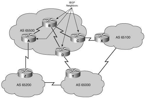
Understanding how BGP works is important to avoid creating problems for your AS as a result of running BGP. For example, enterprise AS 65500 in Figure 8-3 is learning routes from both ISP-A and ISP-B via EBGP and is also running IBGP on all of its routers. Autonomous system 65500 learns about routes and chooses the best way to each one based on the configuration of the routers in the AS and the BGP routes passed from the ISPs. If one of the connections to the ISPs goes down, traffic will be sent through the other ISP.

One of the routes that AS 65500 learns from ISP-A is the route to 172.18.0.0/16. If that route is passed through AS 65500 using IBGP and is mistakenly announced to ISP-B, then ISP-B might decide that the best way to get to 172.18.0.0/16 is through AS 65500, instead of through the Internet. AS 65500 would then be considered a transit AS (an ISP); this would be a very undesirable situation. AS 65500 wants to have a redundant Internet connection, but does not want to act as a transit AS between ISP-A and ISP-B. Careful BGP configuration is required to avoid this situation.
Multihoming is when an AS has more than one connection to the Internet. Two typical reasons for multihoming are as follows:
To increase the reliability of the connection to the Internet—. If one connection fails, the other connection remains available.
To increase the performance of the connection—. Better paths can be used to certain destinations.
The benefits of BGP are apparent when an AS has multiple EBGP connections to either a single ISP or multiple ISPs. Having multiple connections enables an organization to have redundant connections to the Internet so that if a single path becomes unavailable, connectivity can still be maintained.
An organization can be multihomed to either a single ISP or to multiple ISPs. A drawback to having all of your connections to a single ISP is that connectivity issues in that single ISP can cause your AS to lose connectivity to the Internet. By having connections to multiple ISPs, an organization gains the following benefits:
Has redundancy with the multiple connections
Is not tied into the routing policy of a single ISP
Has more paths to the same networks for better policy manipulation
A multihomed AS will run EBGP with its external neighbors and might also run IBGP internally.
If an organization has determined that it will perform multihoming with BGP, three common ways to do this are as follows:
Each ISP passes only a default route to the AS—. The default route is passed to the internal routers.
Each ISP passes only a default route and provider-owned specific routes to the AS—. These routes can be passed to internal routers, or all internal routers in the transit path can run BGP and pass these routes between them.
Each ISP passes all routes to the AS—. All internal routers in the transit path run BGP and pass these routes between them.
The sections that follow describe these options in greater detail.
The first multihoming option is to receive only a default route from each ISP. This configuration requires the least resources within the AS because a default route is used to reach any external destinations. The AS sends all of its routes to the ISPs, which process and pass the routes on to other autonomous systems.
If a router in the AS learns about multiple default routes, the local IGP installs the best default route into the routing table. From the perspective of this router, it takes the default route with the least-cost IGP metric. This IGP default route will route packets that are destined to the external networks to an edge router of this AS, which is running EBGP with the ISPs. The edge router will use the BGP default route to reach all external networks.
The route that inbound packets take to reach the AS is decided outside of the AS (within the ISPs and other autonomous systems).
Regional ISPs that have multiple connections to national or international ISPs commonly implement this option. The regional ISPs do not use BGP for path manipulation; however, they require the capability of adding new customers and the networks of the customers. If the regional ISP does not use BGP, then each time that the regional ISP adds a new set of networks, the customers must wait until the national ISPs add these networks to their BGP process and place static routes pointing at the regional ISP. By running EBGP with the national or international ISPs, the regional ISP needs to add only the new networks of the customers to its BGP process. These new networks automatically propagate across the Internet with minimal delay.
A customer that chooses to receive default routes from all providers must understand the following limitations of this option:
Path manipulation cannot be performed because only a single route is being received from each ISP.
Bandwidth manipulation is extremely difficult and can be accomplished only by manipulating the IGP metric of the default route.
Diverting some of the traffic from one exit point to another is challenging because all destinations are using the same default route for path selection.
Figure 8-4 illustrates an example. AS 65000 and AS 65250 send default routes into AS 65500. The ISP that a specific router within AS 65500 uses to reach any external address is decided by the IGP metric that is used to reach the default route within the autonomous system. For example, if AS 65500 uses RIP, Router C selects the route with the lowest hop count to the default route when sending packets to network 172.16.0.0.

In the second design option for multihoming, all ISPs pass default routes plus select specific routes to the AS.
An enterprise that is running EBGP with an ISP and that wants a partial routing table generally receives the networks that the ISP and its other customers own. The enterprise can also receive the routes from any other AS.
Major ISPs are assigned between 2000 and 10,000 CIDR blocks of IP addresses from the IANA, which they reassign to their customers. If the ISP passes this information to a customer that wants only a partial BGP routing table, the customer can redistribute these routes into its IGP. The internal routers of the customer (these routers are not running BGP) can then receive these routes via redistribution. They can take the nearest exit point based on the best metric of specific networks instead of taking the nearest exit point based on the default route.
Acquiring a partial BGP table from each provider is beneficial because path selection will be more predictable than when using a default route.
Figure 8-5 illustrates an example. ISPs in AS 65000 and AS 64900 send default routes and the routes that each ISP owns to AS 64500. The enterprise (AS 64500) asked both providers to also send routes to networks in AS 64520 because of the amount of traffic between AS 64520 and AS 64500.
By running IBGP between the internal routers within AS 64500, AS 64500 can choose the optimal path to reach the customer networks (AS 64520 in this case). The routes to AS 64100 and to other autonomous systems (not shown in the figure) that are not specifically advertised to AS 64500 by ISP A and ISP B are decided by the IGP metric that is used to reach the default route within the AS.
In the third multihoming option, all ISPs pass all routes to the AS, and IBGP is run on at least all the routers in the transit path in this AS. This option allows the internal routers of the AS to take the path through the best ISP for each route.
This configuration requires a lot of resources within the AS because it must process all the external routes.
The AS sends all its routes to the ISPs, which process the routes and pass them to other autonomous systems.
Figure 8-6 illustrates an example. AS 65000 and AS 64900 send all routes into AS 64500. The ISP that a specific router within AS 64500 uses to reach the external networks is determined by the BGP protocol. The routers in AS 64500 can be configured to influence the path to certain networks. For example, Router A and Router B can influence the outbound traffic from AS 64500.

Internal routing protocols announce a list of networks and the metrics to get to each network. In contrast, BGP routers exchange network reachability information, called path vectors, made up of path attributes, as illustrated in Figure 8-7. The path vector information includes a list of the full path of BGP AS numbers (hop-by-hop) necessary to reach a destination network. Other attributes include the IP address to get to the next AS (the next-hop attribute) and how the networks at the end of the path were introduced into BGP (the origin code attribute); the later “BGP Attributes” section describes all the BGP attributes in detail.
This AS path information is used to construct a graph of loop-free autonomous systems and is used to identify routing policies so that restrictions on routing behavior can be enforced based on the AS path.
Key Point: The BGP AS Path Is Guaranteed to Be Loop Free
The BGP AS path is guaranteed to always be loop free. A router running BGP does not accept a routing update that already includes its AS number in the path list, because the update has already passed through its AS, and accepting it again will result in a routing loop.
BGP is designed to scale to huge internetworks, such as the Internet.
BGP allows routing-policy decisions to be applied to the path of BGP AS numbers so that routing behavior can be enforced at the AS level and to determine how data will flow through the AS. These policies can be implemented for all networks owned by an AS, for a certain CIDR block of network numbers (prefixes), or for individual networks or subnetworks. The policies are based on the attributes carried in the routing information and configured on the routers.
Key Point: BGP Can Advertise Only the Routes It Uses
BGP specifies that a BGP router can advertise to its peers in neighboring autonomous systems only those routes that it uses. This rule reflects the hop-by-hop routing paradigm generally used throughout the current Internet.
Some policies cannot be supported by the hop-by-hop routing paradigm and, thus, require techniques such as source routing to enforce. For example, BGP does not allow one AS to send traffic to a neighboring AS, intending that the traffic take a different route from that taken by traffic originating in that neighboring AS. In other words, you cannot influence how a neighboring AS will route your traffic, but you can influence how your traffic gets to a neighboring AS. However, BGP can support any policy conforming to the hop-by-hop routing paradigm.
Because the current Internet uses only the hop-by-hop routing paradigm, and because BGP can support any policy that conforms to that paradigm, BGP is highly applicable as an inter-AS routing protocol for the current Internet.
For example, in Figure 8-8, the following paths are possible for AS 64512 to reach networks in AS 64700, through AS 64520:
64520 64600 64700
64520 64600 64540 64550 64700
64520 64540 64600 64700
64520 64540 64550 64700
Autonomous system 64512 does not see all these possibilities. Autonomous system 64520 advertises to AS 64512 only its best path, 64520 64600 64700, the same way that IGPs announce only their best least-cost routes. This path is the only path through AS 64520 that AS 64512 sees. All packets that are destined for 64700 via 64520 take this path, because it is the AS-by-AS (hop-by-hop) path that AS 64520 uses to reach the networks in AS 64700. Autonomous system 64520 does not announce the other paths, such as 64520 64540 64600 64700, because it does not choose any of those paths as the best path, based on the BGP routing policy in AS 64520.
AS 64512 does not learn of the second-best path, or any other paths from 64520, unless the best path through AS 64520 becomes unavailable.
Even if AS 64512 were aware of another path through AS 64520 and wanted to use it, AS 64520 would not route packets along that other path, because AS 64520 selected 64520 64600 64700 as its best path, and all AS 64520 routers will use that path as a matter of BGP policy. BGP does not let one AS send traffic to a neighboring AS, intending that the traffic take a different route from that taken by traffic originating in the neighboring AS.
To reach the networks in AS 64700, AS 64512 can choose to use the path through AS 64520 or it can choose to go through the path that AS 64530 is advertising. Autonomous system 64512 selects the best path to take based on its own BGP routing policies.
BGP use in an AS is most appropriate when the effects of BGP are well-understood and at least one of the following conditions exists:
The AS allows packets to transit through it to reach other autonomous systems (for example, it is a service provider).
The AS has multiple connections to other autonomous systems.
Routing policy and route selection for traffic entering and leaving the AS must be manipulated.
If an enterprise has a policy that requires it to differentiate between its traffic and traffic from its ISP, the enterprise must connect to its ISP using BGP. If, instead, an enterprise is connected to its ISP with a static route, traffic from that enterprise is indistinguishable from traffic from the ISP for policy decision-making purposes.
BGP was designed to allow ISPs to communicate and exchange packets. These ISPs have multiple connections to one another and have agreements to exchange updates. BGP is the protocol that is used to implement these agreements between two or more autonomous systems. If BGP is not properly controlled and filtered, it has the potential to allow an outside AS to affect the traffic flow to your AS. For example, if you are a customer connected to ISP-A and ISP-B (for redundancy), you want to implement a routing policy to ensure that ISP-A does not send traffic to ISP-B via your AS. You want to be able to receive traffic destined for your AS through each ISP, but you do not want to waste valuable resources and bandwidth within your AS to route traffic for your ISPs. This chapter focuses on how BGP operates and how to configure it properly so that you can prevent this from happening.
BGP is not always the appropriate solution to interconnect autonomous systems. For example, if there is only one exit path from the AS, a default or static route is appropriate; using BGP will not accomplish anything except to use router CPU resources and memory. If the routing policy that will be implemented in an AS is consistent with the policy implemented in the ISP AS, it is not necessary or even desirable to configure BGP in that AS. The only time BGP will be required is when the local policy differs from the ISP policy.
Do not use BGP if one or more of the following conditions exist:
A single connection to the Internet or another AS
Lack of memory or processor power on routers to handle constant BGP updates
You have a limited understanding of route filtering and the BGP path-selection process
In these cases, use static or default routes instead, as discussed in Chapter 2.
What type of protocol is BGP? Chapter 2 covers the characteristics of distance vector and link-state routing protocols. BGP is sometimes categorized as an advanced distance vector protocol, but it is actually a path vector protocol. BGP has many differences from standard distance vector protocols, such as RIP.
BGP uses the Transmission Control Protocol (TCP) as its transport protocol, which provides connection-oriented reliable delivery. In this way, BGP assumes that its communication is reliable and, therefore, BGP does not have to implement any retransmission or error-recovery mechanisms, like EIGRP does. BGP information is carried inside TCP segments using protocol 179; these segments are carried inside IP packets. Figure 8-9 illustrates this concept.

Note
BGP is the only IP routing protocol to use TCP as its transport layer. OSPF and EIGRP reside directly above the IP layer. IS-IS is at the network layer. RIP uses the User Datagram Protocol (UDP) for its transport layer.
Key Point: BGP Uses TCP to Communicate Between Neighbors
Two routers speaking BGP establish a TCP connection with one another and exchange messages to open and confirm the connection parameters. These two routers are called BGP peer routers or BGP neighbors.
After the TCP connection is made, full BGP routing tables (described in the later “BGP Tables” section) are exchanged. However, because the connection is reliable, BGP routers need to send only changes (incremental updates) after that. Periodic routing updates are not required on a reliable link, so triggered updates are used. BGP sends keepalive messages, similar to the hello messages sent by OSPF, IS-IS, and EIGRP.
OSPF and EIGRP have their own internal functions to ensure that update packets are explicitly acknowledged. These protocols use a one-for-one window so that if either OSPF or EIGRP has multiple packets to send, the next packet cannot be sent until an acknowledgment from the first update packet is received. This process can be very inefficient and cause latency issues if thousands of update packets must be exchanged over relatively slow serial links; however, OSPF and EIGRP rarely have thousands of update packets to send. For example, EIGRP can hold more than 100 networks in one EIGRP update packet, so 100 EIGRP update packets can hold up to 10,000 networks. Most organizations do not have 10,000 subnets.
BGP, on the other hand, has more than 190,000 networks (and growing) on the Internet to advertise, and it uses TCP to handle the acknowledgment function. TCP uses a dynamic window, which allows for up to 65,576 bytes to be outstanding before it stops and waits for an acknowledgment. For example, if 1000-byte packets are being sent and the maximum window size is being used, BGP would have to stop and wait for an acknowledgment only when 65 packets had not been acknowledged.
Note
The CIDR report, at http://www.cidr-report.org/, is a good reference site to see the current size of the Internet routing tables and other related information.
TCP is designed to use a sliding window, where the receiver acknowledges at the halfway point of the sending window. This method allows any TCP application, such as BGP, to continue streaming packets without having to stop and wait, as OSPF or EIGRP would require.
No single router can handle communications with the tens of thousands of the routers that run BGP and are connected to the Internet, representing more than 22,000 autonomous systems. A BGP router forms a direct neighbor relationship with a limited number of other BGP routers. Through these BGP neighbors, a BGP router learns of the paths through the Internet to reach any advertised network.
Any router that runs BGP is called a BGP speaker.
Key Point: BGP Peer = BGP Neighbor
A BGP peer, also known as a BGP neighbor, is a BGP speaker that is configured to form a neighbor relationship with another BGP speaker for the purpose of directly exchanging BGP routing information with one another.
A BGP speaker has a limited number of BGP neighbors with which it peers and forms a TCP-based relationship, as illustrated in Figure 8-10. BGP peers can be either internal or external to the AS.

Note
A BGP peer must be configured under the BGP process with a neighbor command. This command instructs the BGP process to establish a relationship with the neighbor at the address listed in the command and to exchange BGP routing updates with that neighbor.
BGP configuration is described later, in the “Configuring BGP” section.
Recall that when BGP is running between routers in different autonomous systems, it is called EBGP. Routers running EBGP are usually directly connected to each other, as shown in Figure 8-11.

An EBGP neighbor is a router outside this AS; an IGP is not run between the EBGP neighbors. For two routers to exchange BGP routing updates, the TCP reliable transport layer on each side must successfully pass the TCP three-way handshake before the BGP session can be established. Therefore, the IP address used in the neighbor command must be reachable without using an IGP. This can be accomplished by pointing at an address that can be reached through a directly connected network or by using static routes to that IP address. Generally, the neighbor address used is the address of the directly connected network.
Recall that when BGP is running between routers within the same AS, it is called IBGP. IBGP is run within an AS to exchange BGP information so that all internal BGP speakers have the same BGP routing information about outside autonomous systems and so this information can be passed to other autonomous systems.
Routers running IBGP do not have to be directly connected to each other, as long as they can reach each other so that TCP handshaking can be performed to set up the BGP neighbor relationships. The IBGP neighbor can be reached by a directly connected network, static routes, or an internal routing protocol. Because multiple paths generally exist within an AS to reach other routers, a loopback address is usually used in the BGP neighbor command to establish the IBGP sessions.
For example, in Figure 8-12, Routers A, D, and C learn the paths to the external autonomous systems from their respective EBGP neighbors (Routers Z, Y, and X). If the link between Routers D and Y goes down, Router D must learn new routes to the external autonomous systems. Other BGP routers within AS 65500 that were using Router D to get to external networks must also be informed that the path through Router D is unavailable. Those BGP routers within AS 65500 need to have the alternative paths through Routers A and C in their BGP topology database. You must set up IBGP sessions between all routers in the transit path in AS 65500 so that each router in the transit path within the AS learns about paths to the external networks via IBGP.
This section explains why IBGP route propagation requires all routers in the transit path in an AS to run IBGP.
BGP was originally intended to run along the borders of an AS, with the routers in the middle of the AS ignorant of the details of BGP—hence the name “Border Gateway Protocol.” A transit AS, such as the one shown in Figure 8-13, is an AS that routes traffic from one external AS to another external AS. As mentioned earlier, transit autonomous systems are typically ISPs. All routers in a transit AS must have complete knowledge of external routes. Theoretically, one way to achieve this goal is to redistribute BGP routes into an IGP at the edge routers; however, this approach has problems.

Because the current Internet routing table is very large, redistributing all the BGP routes into an IGP is not a scalable way for the interior routers within an AS to learn about the external networks. Another method that you can use is to run IBGP on all routers within the AS.
A nontransit AS, such as an organization that is multihoming with two ISPs, does not pass routes between the ISPs. To make proper routing decisions, however, the BGP routers within the AS still require knowledge of all BGP routes passed to the AS.
BGP does not work in the same manner as IGPs. Because the designers of BGP could not guarantee that an AS would run BGP on all routers, a method had to be developed to ensure that IBGP speakers could pass updates to one another while ensuring that no routing loops would exist.
To avoid routing loops within an AS, BGP specifies that routes learned through IBGP are never propagated to other IBGP peers. Recall that the neighbor command enables BGP updates between BGP speakers. By default, each BGP speaker is assumed to have a neighbor statement for all other IBGP speakers in the AS—this is known as full mesh IBGP.
If the sending IBGP neighbor is not fully meshed with each IBGP router, the routers that are not peering with this router will have different IP routing tables than the routers that are peering with it. The inconsistent routing tables can cause routing loops or routing black holes, because the default assumption by all routers running BGP within an AS is that each BGP router exchanges IBGP information directly with all other BGP routers in the AS.
By fully meshing all IBGP neighbors, when a change is received from an external AS, the BGP router for the local AS is responsible for informing all other IBGP neighbors of the change. IBGP neighbors that receive this update do not send it to any other IBGP neighbor, because they assume that the sending IBGP neighbor is fully meshed with all other IBGP speakers and has sent each IBGP neighbor the update.
The top network in Figure 8-14 shows IBGP update behavior in a partially meshed neighbor environment. Router B receives a BGP update from Router A. Router B has two IBGP neighbors, Routers C and D, but does not have an IBGP neighbor relationship with Router E. Routers C and D learn about any networks that were added or withdrawn behind Router B. Even if Routers C and D have IBGP neighbor sessions with Router E, they assume that the AS is fully meshed for IBGP and do not replicate the update and send it to Router E. Sending the IBGP update to Router E is Router B’s responsibility, because it is the router with firsthand knowledge of the networks in and beyond AS 65101. Router E does not learn of any networks through Router B and does not use Router B to reach any networks in AS 65101 or other autonomous systems behind AS 65101.

In the lower portion of Figure 8-14, IBGP is fully meshed. When Router B receives an update from Router A, it updates all three of its IBGP peers, Router C, Router D, and Router E. OSPF, the IGP, is used to route the TCP segment containing the BGP update from Router A to Router E, because these two routers are not directly connected. The update is sent once to each neighbor and not duplicated by any other IBGP neighbor, which reduces unnecessary traffic. In fully meshed IBGP, each router assumes that every other internal router has a neighbor statement that points to each IBGP neighbor.
TCP was selected as the transport layer for BGP because TCP can move a large volume of data reliably. With the very large full Internet routing table changing constantly, using TCP for windowing and reliability was determined to be the best solution, as opposed to developing a BGP one-for-one windowing capability like OSPF or EIGRP.
TCP sessions cannot be multicast or broadcast because TCP has to ensure the delivery of packets to each recipient. Because TCP cannot use broadcasting, BGP cannot use it either.
Because each IBGP router needs to send routes to all the other IBGP neighbors in the same AS (so that they all have a complete picture of the routes sent to the AS) and they cannot use broadcast, they must use fully meshed BGP (TCP) sessions.
When all routers running BGP in an AS are fully meshed and have the same database as a result of a consistent routing policy, they can apply the same path-selection formula. The path-selection results will therefore be uniform across the AS. Uniform path selection across the AS means no routing loops and a consistent policy for exiting and entering the AS.
Figure 8-15 illustrates how routing might not work if all routers in a transit path are not running BGP.

In this example, Routers A, B, E, and F are the only ones running BGP. Router B has an EBGP neighbor statement for Router A and an IBGP neighbor statement for Router E. Router E has an EBGP neighbor statement for Router F and an IBGP neighbor statement for Router B. Routers C and D are not running BGP. Routers B, C, D and E are running OSPF as their IGP.
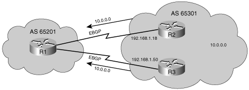
Network 10.0.0.0 is owned by AS 65101 and is advertised by Router A to Router B via an EBGP session. Router B advertises it to Router E via an IBGP session. Routers C and D never learn about this network because it is not redistributed into the local routing protocol (OSPF in this example), and Routers C and D are not running BGP. If Router E advertises this network to Router F in AS 65103, and Router F starts forwarding packets to network 10.0.0.0 through AS 65102, where would Router E send the packets?
Router E would send the packets to its BGP peer, Router B. To get to Router B, however, the packets must go through Router C or D, but those routers do not have an entry in their routing tables for network 10.0.0.0. Thus, when Router E forwards packets with a destination address in network 10.0.0.0 to either Routers C or D, those routers discard the packets.
Even if Routers C and D have a default route going to the exit points of the AS (Routers B and E), there is a good chance that when Router E sends a packet for network 10.0.0.0 to Routers C or D, those routers may send it back to Router E, which will forward it again to Routers C or D, causing a routing loop. To solve this problem, BGP must be implemented on Routers C and D.
Key Point: BGP Synchronization Rule
The BGP synchronization rule states that a BGP router should not use, or advertise to an external neighbor, a route learned by IBGP, unless that route is local or is learned from the IGP.
In the past, best practice dictated redistributing BGP into the IGP running in an autonomous system, so that IBGP was not needed in every router in the transit path. In this case, synchronization was needed to make sure that packets did not get lost, so synchronization was on by default. As the Internet grew, the number of routes in the BGP table became too much for the IGPs to handle, so the best practice was changed to not redistributing BGP into the IGP, but instead using IBGP on all routers in the transit path. In this case, synchronization is not needed; thus, it is now off by default.
Key Point: Synchronization Is Disabled by Default
BGP synchronization is disabled by default in Cisco IOS Software Release 12.2(8)T and later; it was on by default in earlier Cisco IOS Software releases.
With the default of synchronization disabled, BGP can use and advertise to external BGP neighbor routes learned from an IBGP neighbor that are not present in the local routing table.
BGP synchronization is unnecessary in some situations. It is safe to have BGP synchronization off (disabled) only if all routers in the transit path in the autonomous system are running full-mesh IBGP, for the reasons discussed in the previous section.
If synchronization is enabled and your autonomous system is passing traffic from one autonomous system to another, BGP should not advertise a route before all routers in your autonomous system have learned about the route via IGP. In other words, BGP and the IGP must be synchronized before networks learned from an IBGP neighbor can be used.
If synchronization is enabled, a router learning a route via IBGP waits until the IGP has propagated the route within the autonomous system and then advertises it to external peers. This is done so that all routers in the autonomous system are synchronized and can route traffic that the autonomous system advertises to other autonomous systems it can route. The BGP synchronization rule also ensures consistency of information throughout the autonomous system and avoids black holes (for example, advertising a destination to an external neighbor when not all the routers within the autonomous system can reach the destination) within the autonomous system.
Having synchronization disabled allows the routers to carry fewer routes in IGP and allows BGP to converge more quickly because it can advertise the routes as soon as it learns them.
Enable synchronization if there are routers in the BGP transit path in the autonomous system that are not running BGP (and therefore the routers do not have full-mesh IBGP within the autonomous system).
Figure 8-16 illustrates an example. Routers A, B, C, and D are all running IBGP and an IGP with each other (full-mesh IBGP). There are no matching IGP routes for the BGP routes (Routers A and B are not redistributing the BGP routes into the IGP). Routers A, B, C, and D have IGP routes to the internal networks of autonomous system 65500 but do not have IGP routes to external networks, such as 172.16.0.0.

Router B advertises the route to 172.16.0.0 to the other routers in AS 65500 using IBGP.
If synchronization is on in AS 65500 in Figure 8-16, the following happens:
Router B uses the route to 172.16.0.0 and installs it in its routing table.
Routers A, C, and D do not use or advertise the route to 172.16.0.0.
Router E does not hear about 172.16.0.0. If Router E receives traffic destined for network 172.16.0.0, it does not have a route for that network and cannot forward the traffic.
If synchronization is off (the default) in AS 65500 in Figure 8-16, the following happens:
Routers A, C, and D use and advertise the route to 172.16.0.0 that they receive via IBGP and install it in their routing tables (assuming, of course, that Routers A, C, and D can reach the next-hop address for 172.16.0.0).
Router E hears about 172.16.0.0 from Router A. Router E has a route to 172.16.0.0 and can send traffic destined for that network.
If Router E sends traffic for 172.16.0.0, Routers A, C, and D route the packets correctly to Router B. Router E sends the packets to Router A, and Router A forwards them to Router C. Router C has learned a route to 172.16.0.0 via IBGP and, therefore, forwards the packets to Router D. Router D forwards the packets to Router B. Router B forwards the packets to Router F, which routes them to network 172.16.0.0.
In modern autonomous systems, because the size of the Internet routing table is large, redistributing from BGP into an IGP is not scalable; therefore, most modern autonomous systems run full-mesh IBGP and do not require synchronization. Some advanced BGP configuration methods, such as route reflectors and confederations, reduce the IBGP full-mesh requirements (route reflectors are discussed in Appendix E, “BGP Supplement”).
As shown in Figure 8-17, a router running BGP keeps its own table for storing BGP information received from and sent to other routers.

Key Point: BGP Table
This table of BGP information is known by many names in various documents, including
BGP table
BGP topology table
BGP topology database
BGP routing table
BGP forwarding database
This table is separate from the IP routing table in the router.
The router can be configured to share information between the BGP table and the IP routing table.
BGP also keeps a neighbor table containing a list of neighbors with which it has a BGP connection.
For BGP to establish an adjacency, you must configure it explicitly for each neighbor. BGP forms a TCP relationship with each of the configured neighbors and keeps track of the state of these relationships by periodically sending a BGP/TCP keepalive message.
After establishing an adjacency, the neighbors exchange the BGP routes that are in their IP routing table. Each router collects these routes from each neighbor with which it successfully established an adjacency and places them in its BGP forwarding database. All routes that have been learned from each neighbor are placed in the BGP forwarding database. The best routes for each network are selected from the BGP forwarding database using the BGP route selection process (discussed in the section “The Route Selection Decision Process,” later in this chapter) and then are offered to the IP routing table.
Each router compares the offered BGP routes to any other possible paths to those networks in its IP routing table, and the best route, based on administrative distance, is installed in the IP routing table. EBGP routes (BGP routes learned from an external AS) have an administrative distance of 20. IBGP routes (BGP routes learned from within the AS) have an administrative distance of 200.
BGP defines the following message types:
Open
Keepalive
Update
Notification
After a TCP connection is established, the first message sent by each side is an open message. If the open message is acceptable, a keepalive message confirming the open message is sent back by the side that received the open message.
When the open is confirmed, the BGP connection is established, and update, keepalive, and notification messages can be exchanged.
BGP peers initially exchange their full BGP routing tables. From then on, incremental updates are sent as the routing table changes. Keepalive packets are sent to ensure that the connection is alive between the BGP peers, and notification packets are sent in response to errors or special conditions.
An open message includes the following information:
Version—. This 8-bit field indicates the message’s BGP version number. The highest common version that both routers support is used. Most BGP implementations today use the current version, BGP-4.
My autonomous system—. This 16-bit field indicates the sender’s AS number. The peer router verifies this information; if it is not the AS number expected, the BGP session is torn down.
Hold time—. This 16-bit field indicates the maximum number of seconds that can elapse between the successive keepalive or update messages from the sender. Upon receipt of an open message, the router calculates the value of the hold timer to use by using the smaller of its configured hold time and the hold time received in the open message.
BGP router identifier (router ID)—. This 32-bit field indicates the sender’s BGP identifier. The BGP router ID is an IP address assigned to that router and is determined at startup. The BGP router ID is chosen the same way the OSPF router ID is chosen; it is the highest active IP address on the router, unless a loopback interface with an IP address exists, in which case it is the highest such loopback IP address. Alternatively, the router ID can be statically configured, overriding the automatic selection.
Optional parameters—. A length field indicates the total length of the optional parameters field in octets. These parameters are Type, Length, and Value (TLV)-encoded. An example of an optional parameter is session authentication.
BGP does not use any transport protocol-based keepalive mechanism to determine whether peers can be reached. Instead, keepalive messages are exchanged between peers often enough to keep the hold timer from expiring. If the negotiated hold time interval is 0, periodic keepalive messages are not sent. A keepalive message consists of only a message header.
An update message has information on one path only; multiple paths require multiple messages. All the attributes in the message refer to that path, and the networks are those that can be reached through that path. An update message might include the following fields:
Withdrawn routes—. A list of IP address prefixes for routes that are being withdrawn from service, if any.
Path attributes—. The AS-path, origin, local preference, and so forth, as discussed in the next section. Each path attribute includes the attribute type, attribute length, and attribute value (TLV). The attribute type consists of the attribute flags, followed by the attribute type code.
Network layer reachability information—. A list of IP address prefixes that can be reached by this path.
A BGP router sends a notification message when it detects an error condition. The BGP router closes the BGP connection immediately after sending the notification message. Notification messages include an error code, an error subcode, and data related to the error.
BGP routers send BGP update messages about destination networks to other BGP routers. As described in the previous section, update messages can contain network layer reachability information, which is a list of one or more networks (IP address prefixes), and path attributes, which are a set of BGP metrics describing the path to these networks (routes). The following are some terms defining how these attributes are implemented:
An attribute is either well-known or optional, mandatory or discretionary, and transitive or nontransitive. An attribute might also be partial.
Not all combinations of these characteristics are valid; path attributes fall into four separate categories:
Only optional transitive attributes might be marked as partial.
These characteristics are described in the following sections.
A well-known attribute is one that all BGP implementations must recognize and propagate to BGP neighbors.
A well-known mandatory attribute must appear in all BGP updates. A well-known discretionary attribute does not have to be present in all BGP updates.
Attributes that are not well-known are called optional. Optional attributes are either transitive or nontransitive.
BGP routers that implement an optional attribute might propagate it to other BGP neighbors, based on its meaning.
BGP routers that do not implement an optional transitive attribute should pass it to other BGP routers untouched and mark the attribute as partial.
BGP routers that do not implement an optional nontransitive attribute must delete the attribute and must not pass it to other BGP routers.
The attributes defined by BGP include the following:
Well-known mandatory attributes:
AS-path
Next hop
Origin
Well-known discretionary attributes:
Local preference
Atomic aggregate
Optional transitive attributes:
Aggregator
Community
Optional nontransitive attribute:
Multiexit-discriminator (MED)
In addition, Cisco has defined a weight attribute for BGP. The weight is configured locally on a router and is not propagated to any other BGP routers.
The AS-path, next-hop, origin, local preference, community, MED, and weight attributes are expanded upon in the following sections. The atomic aggregate and aggregator attributes are discussed in Appendix E, as is BGP community configuration.
The AS-path attribute is a well-known mandatory attribute. Whenever a route update passes through an AS, the AS number is prepended to that update (in other words, it is put at the beginning of the list) when it is advertised to the next EBGP neighbor.
Key Point: AS-Path Attribute
The AS-path attribute is the list of AS numbers that a route has traversed to reach a destination, with the number of the AS that originated the route at the end of the list.
In Figure 8-18, Router A advertises network 192.168.1.0 in AS 64520. When that route traverses AS 65500, Router C prepends its own AS number to it. When the route to 192.168.1.0 reaches Router B, it has two AS numbers attached to it. From Router B’s perspective, the path to reach 192.168.1.0 is (65500, 64520).

The same applies for 192.168.2.0 and 192.168.3.0. Router A’s path to 192.168.2.0 is (65500 65000)—it traverses AS 65500 and then AS 65000. Router C has to traverse path (65000) to reach 192.168.2.0 and path (64520) to reach 192.168.1.0.
BGP routers use the AS-path attribute to ensure a loop-free environment. If a BGP router receives a route in which its own AS is part of the AS-path attribute, it does not accept the route.
Autonomous system numbers are prepended only by routers advertising routes to EBGP neighbors. Routers advertising routes to IBGP neighbors do not change the AS-path attribute.
The BGP next-hop attribute is a well-known mandatory attribute that indicates the next-hop IP address that is to be used to reach a destination. BGP, like IGPs, is a hop-by-hop routing protocol. However, unlike IGPs, BGP routes AS-by-AS, not router-by-router, and the default next-hop is the next AS. The next-hop address for a network from another AS is an IP address of the entry point of the next AS along the path to that destination network.
Key Point: EBGP Next Hop
For EBGP, the next hop is the IP address of the neighbor that sent the update.
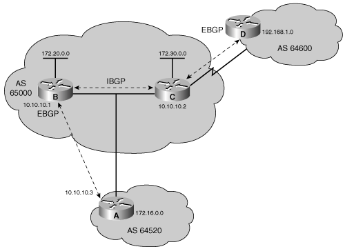
In Figure 8-19, Router A advertises 172.16.0.0 to Router B, with a next hop of 10.10.10.3, and Router B advertises 172.20.0.0 to Router A, with a next hop of 10.10.10.1. Therefore, Router A uses 10.10.10.1 as the next-hop attribute to get to 172.20.0.0, and Router B uses 10.10.10.3 as the next-hop attribute to get to 172.16.0.0.

Key Point: IBGP Next Hop
For IBGP, the protocol states that the next hop advertised by EBGP should be carried into IBGP.
Because of this rule, Router B in Figure 8-19 advertises 172.16.0.0 to its IBGP peer Router C, with a next hop of 10.10.10.3 (Router A’s address). Therefore, Router C knows that the next hop to reach 172.16.0.0 is 10.10.10.3, not 172.20.10.1, as you might expect.
It is very important, therefore, that Router C knows how to reach the 10.10.10.0 subnet, either via an IGP or a static route; otherwise, it will drop packets destined for 172.16.0.0, because it will not be able to get to the next-hop address for that network.
The IBGP neighboring router performs a recursive lookup to find out how to reach the BGP next-hop address by using its IGP entries in the routing table. For example, Router C in Figure 8-19 learns in a BGP update about network 172.16.0.0/16 from the route source 172.20.10.1, Router B, with a next hop of 10.10.10.3, Router A. Router C installs the route to 172.16.0.0/16 in the routing table with a next hop of 10.10.10.3. Assuming that Router B announces network 10.10.10.0/24 using its IGP to Router C, Router C installs that route in its routing table with a next hop of 172.20.10.1. An IGP uses the source IP address of a routing update (route source) as the next-hop address, whereas BGP uses a separate field for each network to record the next-hop address. If Router C has a packet to send to 172.16.100.1, it looks up the network in the routing table and finds a BGP route with a next hop of 10.10.10.3. Because it is a BGP entry, Router C completes a recursive lookup in the routing table for a path to network 10.10.10.3; there is an IGP route to network 10.10.10.0 in the routing table with a next hop of 172.20.10.1. Router C then forwards the packet destined for 172.16.100.1 to 172.20.10.1.
When running BGP over a multiaccess network such as Ethernet, a BGP router uses the appropriate address as the next-hop address (by changing the next-hop attribute) to avoid inserting additional hops into the path. This feature is sometimes called a third-party next hop.
For example, in Figure 8-20, assume that Routers B and C in AS 65000 are running an IGP, so that Router B can reach network 172.30.0.0 via 10.10.10.2. Router B is also running EBGP with Router A. When Router B sends a BGP update to Router A about 172.30.0.0, it uses 10.10.10.2 as the next hop, not its own IP address (10.10.10.1). This is because the network among the three routers is a multiaccess network, and it makes more sense for Router A to use Router C as a next hop to reach 172.30.0.0, rather than making an extra hop via Router B.
The third-party next-hop address issue also makes sense when you review it from an ISP perspective. A large ISP at a public peering point has multiple routers peering with different neighboring routers; it is not possible for one router to peer with every neighboring router at the major public peering points. For example, in Figure 8-20, Router B might peer with AS 64520, and Router C might peer with AS 64600; however, each router must inform the other IBGP neighbor of reachable networks from other autonomous systems. From the perspective of Router A, it must transit AS 65000 to get to networks in and behind AS 64600. Router A has a neighbor relationship with only Router B in AS 65000; however, Router B does not handle traffic going to AS 64600. Router B gets to AS 64600 through Router C, 10.10.10.2, and Router B must advertise the networks for AS 64600 to Router A, 10.10.10.3. Router B notices that Routers A and C are on the same subnet, so Router B tells Router A to install the AS 64600 networks with a next hop of 10.10.10.2, not 10.10.10.1.
However, if the common medium between routers is a nonbroadcast multiaccess (NBMA) medium, complications might occur.
For example, in Figure 8-21, Routers A, B, and C are connected by Frame Relay. Router B can reach network 172.30.0.0 via 10.10.10.2. When Router B sends a BGP update to Router A about 172.30.0.0, it uses 10.10.10.2 as the next hop, not its own IP address (10.10.10.1). A problem arises if Routers A and C do not know how to communicate directly—in other words, if Routers A and C do not have a Frame Relay map entry to reach each other, Router A does not know how to reach the next-hop address on Router C.

This behavior can be overridden in Router B by configuring it to advertise itself as the next-hop address for routes sent to Router A; this configuration is described in the later section “Changing the Next-Hop Attribute”.
The origin is a well-known mandatory attribute that defines the origin of the path information. The origin attribute can be one of three values:
IGP—. The route is interior to the originating AS. This normally happens when a network command is used to advertise the route via BGP. An origin of IGP is indicated with an i in the BGP table.
EGP—. The route is learned via EGP. This is indicated with an e in the BGP table. EGP is considered a historic routing protocol and is not supported on the Internet because it performs only classful routing and does not support CIDR.
Incomplete—. The route’s origin is unknown or is learned via some other means. This usually occurs when a route is redistributed into BGP. (Redistribution is discussed in Chapter 7, “Manipulating Routing Updates,” and Appendix E.) An incomplete origin is indicated with a ? in the BGP table.
Local preference is a well-known discretionary attribute that indicates to routers in the AS which path is preferred to exit the AS.
Local preference is an attribute that is configured on a router and exchanged only among routers within the same AS. The default value for local preference on a Cisco router is 100.
Key Point: Local Preference Is Only for Internal Neighbors
The term local refers to inside the AS. The local preference attribute is sent only to internal BGP neighbors; it is not passed to EBGP peers.
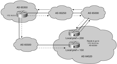
For example, in Figure 8-22, AS 64520 receives updates about network 172.16.0.0 from two directions. Router A and Router B are IBGP neighbors. Assume that the local preference on Router A for network 172.16.0.0 is set to 200 and that the local preference on Router B for network 172.16.0.0 is set to 150. Because the local preference information is exchanged within AS 64520, all traffic in AS 64520 addressed to network 172.16.0.0 is sent to Router A as an exit point from AS 64520.
BGP communities are one way to filter incoming or outgoing routes. BGP communities allow routers to tag routes with an indicator (the community) and allow other routers to make decisions based on that tag. Any BGP router can tag routes in incoming and outgoing routing updates, or when doing redistribution. Any BGP router can filter routes in incoming or outgoing updates or can select preferred routes based on communities (the tag).
BGP communities are used for destinations (routes) that share some common properties and, therefore, share common policies; thus, routers act on the community rather than on individual routes. Communities are not restricted to one network or one AS, and they have no physical boundaries.
Communities are optional transitive attributes. If a router does not understand the concept of communities, it defers to the next router. However, if the router does understand the concept, it must be configured to propagate the community; otherwise, communities are dropped by default.
Note
BGP community configuration is detailed in Appendix E.
The MED attribute, also called the metric, is an optional nontransitive attribute. The MED was known as the inter-AS attribute in BGP-3.
Note
The MED attribute is called the metric in the Cisco IOS; in the output of the show ip bgp command for example, the MED is displayed in the metric column.
Key Point: MED
The MED indicates to external neighbors the preferred path into an AS. This is a dynamic way for an AS to try to influence another AS as to which way it should choose to reach a certain route if there are multiple entry points into the AS.
A lower metric value is preferred.
Unlike local preference, the MED is exchanged between autonomous systems. The MED is sent to EBGP peers; those routers propagate the MED within their AS, and the routers within the AS use the MED, but do not pass it on to the next AS. When the same update is passed on to another AS, the metric will be set back to the default of 0.
Key Point: MED and Local Preference
MED influences inbound traffic to an AS, whereas local preference influences outbound traffic from an AS.
By default, a router compares the MED attribute only for paths from neighbors in the same AS.
By using the MED attribute, BGP is the only protocol that can affect how routes are sent into an AS.
For example, in Figure 8-23, Router B has set the MED attribute to 150, and Router C has set the MED attribute to 200. When Router A receives updates from Routers B and C, it picks Router B as the best next hop to get to AS 65500, because 150 is less than 200.

Note
By default, the MED comparison is done only if the neighboring autonomous system is the same for all routes considered. For the router to compare metrics from neighbors coming from different autonomous systems, the bgp always-compare-med router configuration command must be configured on the router.
The weight attribute is a Cisco-defined attribute used for the path-selection process. The weight is configured locally to a router and is not propagated to any other routers.
Key Point: Weight Attribute
The weight attribute provides local routing policy only and is not propagated to any BGP neighbors.
Routes with a higher weight are preferred when multiple routes to the same destination exist.
The weight can have a value from 0 to 65535. Paths that the router originates have a weight of 32768 by default, and other paths have a weight of 0 by default.
The weight attribute applies when using one router with multiple exit points out of an AS, as compared to the local preference attribute, which is used when two or more routers provide multiple exit points.
In Figure 8-24, Routers B and C learn about network 172.20.0.0 from AS 65250 and propagate the update to Router A. Router A has two ways to reach 172.20.0.0 and must decide which way to go. In the example, Router A is configured to set the weight of updates coming from Router B to 200 and the weight of those coming from Router C to 150. Because the weight for Router B is higher than the weight for Router C, Router A uses Router B as a next hop to reach 172.20.0.0.

After BGP receives updates about different destinations from different autonomous systems, it decides which path to choose to reach each specific destination. Multiple paths might exist to reach a given network; these are kept in the BGP table. As paths for the network are evaluated, those determined not to be the best path are eliminated from the selection criteria but kept in the BGP table in case the best path becomes inaccessible.
Key Point: BGP Chooses Only a Single Best Path
BGP chooses only a single best path to reach a specific destination.
BGP is not designed to perform load balancing; paths are chosen because of policy, not based on bandwidth. The BGP selection process eliminates any multiple paths until a single best path is left.
The best path is submitted to the routing table manager process and is evaluated against any other routing protocols that can also reach that network. The route from the routing protocol with the lowest administrative distance is installed in the routing table.
The decision process is based on the attributes discussed earlier in the “BGP Attributes” section. When faced with multiple routes to the same destination, BGP chooses the best route for routing traffic toward the destination. A path is not considered if it is internal, synchronization is on, and the route is not synchronized (in other words, the route is not in the IGP routing table), or if the path’s next-hop address cannot be reached. Thus, to choose the best route, BGP considers only synchronized routes with no AS loops and a valid next-hop address. The following process summarizes how BGP chooses the best route on a Cisco router:
Prefer the route with the highest weight. (Recall that the weight is Cisco-proprietary and is local to the router only.)
If multiple routes have the same weight, prefer the route with the highest local preference. (Recall that the local preference is used within an AS.)
If multiple routes have the same local preference, prefer the route that was originated by the local router. (A locally originated route has a next hop of 0.0.0.0 in the BGP table.)
If none of the routes were originated by the local router, prefer the route with the shortest AS-path.
If the AS-path length is the same, prefer the lowest-origin code (IGP < EGP < incomplete).
If all origin codes are the same, prefer the path with the lowest MED. (Recall that the MED is exchanged between autonomous systems.)
The MED comparison is done only if the neighboring AS is the same for all routes considered, unless the bgp always-compare-med router configuration command is enabled.
Note
The most recent Internet Engineering Task Force (IETF) decision about BGP MED assigns a value of infinity to a missing MED, making a route lacking the MED variable the least preferred. The default behavior of BGP routers running Cisco IOS Software is to treat routes without the MED attribute as having a MED of 0, making a route lacking the MED variable the most preferred. To configure the router to conform to the IETF standard, use the bgp bestpath med missing-as-worst router configuration command.
If the routes have the same MED, prefer external paths (EBGP) over internal paths (IBGP).
If synchronization is disabled and only internal paths remain, prefer the path through the closest IGP neighbor. This means that the router prefers the shortest internal path within the AS to reach the destination (the shortest path to the BGP next-hop).
For EBGP paths, select the oldest route, to minimize the effect of routes going up and down (flapping).
Prefer the route with the lowest neighbor BGP router ID value.
If the BGP router IDs are the same, prefer the route with the lowest neighbor IP address.
Only the best path is entered in the routing table and propagated to the router’s BGP neighbors.
Note
The route selection decision process summarized here does not cover all cases, but it is sufficient for a basic understanding of how BGP selects routes.
For example, suppose that there are seven paths to reach network 10.0.0.0. All paths have no AS loops and valid next-hop addresses, so all seven paths proceed to Step 1, which examines the weight of the paths. All seven paths have a weight of 0, so they all proceed to Step 2, which examines the paths’ local preference. Four of the paths have a local preference of 200, and the other three have a local preference of 100, 100, and 150. The four with a local preference of 200 continue the evaluation process to the next step. The other three remain in the BGP forwarding table but are currently disqualified as the best path.
BGP continues the evaluation process until only a single best path remains. The single best path that remains is offered to the IP routing table as the best BGP path.
Example 8-1. Output from Testing of the maximum-paths Command for BGP
R1#show ip route bgp
B    10.0.0.0/8 [20/0] via 192.168.1.18, 00:00:41
                [20/0] via 192.168.1.50, 00:00:41

R1#show ip bgp
BGP table version is 3, local router ID is 192.168.1.49
Status codes: s suppressed, d damped, h history, * valid, > best, i ->internal
Origin codes: i - IGP, e - EGP, ? - incomplete

   Network          Next Hop            Metric LocPrf Weight Path
*> 10.0.0.0         192.168.1.18             0             0 65301 i
*                   192.168.1.50             0             0 65301 i
This section covers the commands used to configure some of the BGP features discussed in this chapter. The concept of peer groups is described first, because peer groups appear in many of the configuration commands.
Note
The syntax of some BGP configuration commands is similar to the syntax of commands used to configure internal routing protocols. However, there are significant differences in how BGP functions.
In BGP, many neighbors are often configured with the same update policies (for example, they have the same filtering applied). On a Cisco Systems router, neighbors with the same update policies can be grouped into peer groups to simplify configuration and, more importantly, to make updating more efficient and improve performance. When you have many peers, this approach is highly recommended.
Key Point: BGP Peer Group
A BGP peer group is a group of BGP neighbors of the router being configured that all have the same update policies.
Instead of separately defining the same policies for each neighbor, a peer group can be defined with these policies assigned to the peer group. Individual neighbors are then made members of the peer group. The policies of the peer group are similar to a template; the template is then applied to the individual members of the peer group.
Members of the peer group inherit all the peer group’s configuration options. The router can also be configured to override these options for some members of the peer group if these options do not affect outbound updates. In other words, only options that affect the inbound updates can be overridden.
Note
Some earlier IOS releases had a restriction that all EBGP neighbors in a peer group had to be reachable over the same interface. This is because the next-hop attribute would be different for EBGP neighbors accessible on different interfaces. You can get around this restriction by configuring a loopback source address for EBGP peers. This restriction was removed starting in Cisco IOS Software Releases 11.1(18)CC, 11.3(4), and 12.0.
Peer groups are more efficient than defining the same policies for each neighbor, because updates are generated only once per peer group rather than repetitiously for each neighboring router; the generated update is replicated for each neighbor that is part of the peer group.
Thus, peer groups save processing time in generating the updates for all IBGP neighbors and make the router configuration easier to read and manage.
The neighbor peer-group-name peer-group router configuration command is used to create a BGP peer group. The peer-group-name is the name of the BGP peer group to be created. The peer-group-name is local to the router on which it is configured; it is not passed to any other router. You can use another syntax form of the neighbor peer-group command, the neighbor ip-address peer-group peer-group-name router configuration command, to assign neighbors as part of the group after the group has been created. Table 8-3 provides details of this command. Using this command allows you to type the peer group name instead of typing the IP addresses of individual neighbors in other commands, for example, to link a policy to the group of neighboring routers. (Note that you must enter the neighbor peer-group-name peer-group command before the router will accept this second command.)
A neighboring router can be part of only one peer group.
Note
Release 12.0(24)S of Cisco IOS Software introduced the BGP Dynamic Update Peer-Groups feature using peer templates to dynamically optimize update-groups of neighbors for shared outbound policies. More information on this feature can be found at http://www.cisco.com.
The clear ip bgp peer-group peer-group-name EXEC command is used to reset the BGP connections for all members of a BGP peer group. The peer-group-name is the name of the BGP peer group for which connections are to be cleared.
Caution
Resetting BGP sessions will disrupt routing. See the “Resetting BGP Sessions” section later in this chapter for more information about how the clear ip bgp commands operate.
Use the router bgp autonomous-system global configuration command to enter BGP configuration mode, and identify the local AS in which this router belongs. In the command, autonomous-system identifies the local AS. The BGP process needs to be informed of its AS so that when BGP neighbors are configured it can determine whether they are IBGP or EBGP neighbors.
The router bgp command alone does not activate BGP on a router. You must enter at least one subcommand under the router bgp command to activate the BGP process on the router.
Only one instance of BGP can be configured on a router at a time. For example, if you configure your router in AS 65000 and then try to configure the router bgp 65100 command, the router informs you that you are currently configured for AS 65000.
Use the neighbor {ip-address | peer-group-name} remote-as autonomous-system router configuration command to activate a BGP session for external and internal neighbors and to identify a peer router with which the local router will establish a session, as described in Table 8-4.
The IP address used in the neighbor remote-as command is the destination address for all BGP packets going to this neighboring router. For a BGP relationship to be established, this address must be reachable, because BGP attempts to establish a TCP session and exchange BGP updates with the device at this IP address.
The value placed in the autonomous-system field of the neighbor remote-as command determines whether the communication with the neighbor is an EBGP or IBGP session. If the autonomous-system field configured in the router bgp command is identical to the field in the neighbor remote-as command, BGP initiates an internal session, and the IP address specified does not have to be directly connected. If the field values are different, BGP initiates an external session, and the IP address specified must be directly connected, by default.
The network shown in Figure 8-26 uses the BGP neighbor commands; the configurations of Routers A, B, and C are shown in Examples 8-2, 8-3, and 8-4. Router A in AS 65101 has two neighbor statements. In the first statement, neighbor 10.2.2.2 (Router B) is in the same AS as Router A (65101); this neighbor statement defines Router B as an IBGP neighbor. Autonomous system 65101 runs EIGRP between all internal routers. Router A has an EIGRP path to reach IP address 10.2.2.2; as an IBGP neighbor, Router B can be multiple routers away from Router A.

Example 8-2. Configuration of Router A in Figure 8-26
router bgp 65101
  neighbor 10.2.2.2 remote-as 65101
  neighbor 192.168.1.1 remote-as 65102
Example 8-3. Configuration of Router B in Figure 8-26
router bgp 65101
  neighbor 10.1.1.2 remote-as 65101
Example 8-4. Configuration of Router C in Figure 8-26
router bgp 65102
  neighbor 192.168.1.2 remote-as 65101
Router A in Figure 8-26 knows that Router C is an external neighbor because the neighbor statement for Router C uses AS 65102, which is different from the AS number of Router A, AS 65101. Router A can reach AS 65102 via 192.168.1.1, which is directly connected to Router A.
Note
The network in Figure 8-26 is only used to illustrate the difference between configuring IBGP and EBGP sessions. As mentioned earlier, if Router B connects to another autonomous system then all routers in the transit path (Routers A, D, and B in this figure) should be running fully meshed BGP.
To disable (administratively shut down) an existing BGP neighbor or peer group, use the neighbor {ip-address | peer-group-name} shutdown router configuration command. To enable a previously existing neighbor or peer group that had been disabled using the neighbor shutdown command, use the no neighbor {ip-address | peer-group-name} shutdown router configuration command. If you want to implement major policy changes to a neighboring router and you change multiple parameters, you must administratively shut down the neighboring router, implement the changes, and then bring the neighboring router back up.
The BGP neighbor statement tells the BGP process the destination IP address of each update packet. The router must decide which IP address to use as the source IP address in the BGP routing update.
When a router creates a packet, whether it is a routing update, a ping, or any other type of IP packet, the router does a lookup in the routing table for the destination address; the routing table lists the appropriate interface to get to the destination address. The address of this outbound interface is used as that packet’s source address by default.
For BGP packets, this source IP address must match the address in the corresponding neighbor statement on the other router. (In other words, the other router must have a BGP relationship with the packet’s source IP address.) Otherwise, the routers will not be able to establish the BGP session, and the packet will be ignored. BGP does not accept unsolicited updates; it must be aware of every neighboring router and have a neighbor statement for it.
For example, in Figure 8-27, assume that Router D uses the neighbor 10.3.3.1 remote-as 65102 command to establish a relationship with Router A. If Router A is sending the BGP packets to Router D via Router B, the source IP address of the packets will be 10.1.1.1. When Router D receives a BGP packet via Router B, it does not recognize the sender of the BGP packet, because 10.1.1.1 is not configured as a neighbor of Router D. Therefore, the IBGP session between Router A and Router D cannot be established.

A solution to this problem is to establish the IBGP session using a loopback interface when there are multiple paths between the IBGP neighbors.
If the IP address of a loopback interface is used in the neighbor command, some extra configuration must be done on the neighbor router. You must tell BGP to use a loopback interface address rather than a physical interface address as the source address for all BGP packets, including those that initiate the BGP neighbor TCP connection. Use the neighbor {ip-address | peer-group-name} update-source loopback interface-number router configuration command to cause the router to use the address of the specified loopback interface as the source address for BGP connections to this neighbor.
The update-source option in the neighbor command overrides the default source IP address for BGP packets. This peering arrangement also adds resiliency to the IBGP sessions, because the routers are not tied into a physical interface, which might go down for any number of reasons. For example, if a BGP router is using a neighbor address that is assigned to a specific physical interface on another router, and that interface goes down, the router pointing at that address loses its BGP session with that other BGP neighbor. If, instead, the router peers with the loopback interface of the other router, the BGP session is not lost, because the loopback interface is always available as long as the router itself does not fail.
To peer with the loopback interface of an IBGP neighbor, configure each router with a neighbor command using the loopback address of the other neighbor. Both routers must have a route to the loopback address of the other neighbor in their routing table; check to ensure that both routers are announcing their loopback addresses into their local routing protocol. The neighbor update-source command is necessary for both routers.
For example, in Figure 8-28, Router B has Router A as an EBGP neighbor and Router C as an IBGP neighbor. The configurations for Routers B and C are shown in Examples 8-5 and 8-6. The only reachable address that Router B can use to establish a BGP neighbor relationship with Router A is the directly connected address 172.16.1.1. However, Router B has multiple paths to reach Router C, an IBGP neighbor. All networks, including the IP network for Router C’s loopback interface, can be reached from Router B because these two routers exchange EIGRP updates. (Router B and Router A do not exchange EIGRP updates.) The neighbor relationship between Routers B and C is not tied to a physical interface, because each router peers with the loopback interface on the other router and uses its loopback address as the BGP source IP address. If Router B instead peered with 10.1.1.2 on Router C and that interface went down, the BGP neighbor relationship would be lost.
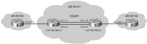
Example 8-5. Configuration of Router B in Figure 8-28
router bgp 65101
  neighbor 172.16.1.1 remote-as 65100
  neighbor 192.168.3.3 remote-as 65101
  neighbor 192.168.3.3 update-source loopback0
!
router eigrp 1
  network 10.0.0.0
  network 192.168.2.0
Example 8-6. Configuration of Router C in Figure 8-28
router bgp 65101
  neighbor 192.168.1.1 remote-as 65102
  neighbor 192.168.2.2 remote-as 65101
  neighbor 192.168.2.2 update-source loopback0
!
router eigrp 1
  network 10.0.0.0
  network 192.168.3.0
If Router B points at loopback address 192.168.3.3 on Router C and Router C points at loopback address 192.168.2.2 on Router B, but neither uses the neighbor update-source command, a BGP session is not established between these routers. Without this command, Router B will send a BGP open packet to Router C with a source IP address of either 10.1.1.1 or 10.2.2.1. Router C will examine the source IP address and attempt to match it against its list of known neighbors; because Router C will not find a match, it will not respond to the open message from Router B.
When peering with an external neighbor, the only address that an EBGP router can reach without further configuration is the interface that is directly connected to that EBGP router. Because IGP routing information is not exchanged with external peers, the router must point to a directly connected address for external neighbors. A loopback interface is never directly connected. Therefore, if you want to peer with a loopback interface instead, you have to add a static route to the loopback pointing to the physical address of the directly connected network (the next-hop address). You must also enable multihop EBGP, with the neighbor {ip-address | peer-group-name} ebgp-multihop [ttl] router configuration command.
This command allows the router to accept and attempt BGP connections to external peers residing on networks that are not directly connected. This command increases the default of one hop for EBGP peers by changing the default Time to Live (TTL) value of 1 and therefore allowing routes to the EBGP loopback address. By default, the TTL is set to 255 with this command. This command is of value when redundant paths exist between EBGP neighbors.
For example, in Figure 8-29, Router A in AS 65102 has two paths to Router B in AS 65101. If Router A uses a single neighbor statement that points to 192.168.1.18 on Router B and that link goes down, the BGP session between these autonomous systems is lost, and no packets pass from one AS to the next, even though another link exists. This problem can be solved if Router A uses two neighbor statements pointing to 192.168.1.18 and 192.168.1.34 on Router B. However, every BGP update that Router A receives will be sent to Router B twice because of the two neighbor statements.
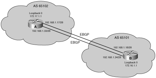
The configurations of Routers A and B are shown in Examples 8-7 and 8-8. As these configurations show, each router instead points to the loopback address of the other router and uses its loopback address as the source IP address for its BGP updates. Because an IGP is not used between autonomous systems, neither router can reach the loopback of the other router without assistance. Each router needs to use two static routes to define the paths available to reach the loopback address of the other router. The neighbor ebgp-multihop command must also be configured to change the default setting of BGP and inform the BGP process that this neighbor IP address is more than one hop away. In these examples, the commands used on Routers A and B inform BGP that the neighbor address is two hops away.
Example 8-7. Configuration of Router A in Figure 8-29
router bgp 65102
  neighbor 172.16.1.1 remote-as 65101
  neighbor 172.16.1.1 update-source loopback0
  neighbor 172.16.1.1 ebgp-multihop 2
ip route 172.16.1.1 255.255.255.255 192.168.1.18
ip route 172.16.1.1 255.255.255.255 192.168.1.34
Example 8-8. Configuration of Router B in Figure 8-29
router bgp 65101
  neighbor 172.17.1.1 remote-as 65102
  neighbor 172.17.1.1 update-source loopback0
  neighbor 172.17.1.1 ebgp-multihop 2
ip route 172.17.1.1 255.255.255.255 192.168.1.17
ip route 172.17.1.1 255.255.255.255 192.168.1.33
Note
Recall that BGP is not designed to perform load balancing; paths are chosen because of policy, not based on bandwidth. BGP will choose only a single best path. Using the loopback addresses and the neighbor ebgp-multihop command as shown in this example allows load balancing, and redundancy, across the two paths between the autonomous systems.
As discussed in the section “The Next-Hop Attribute” earlier in this chapter, it is sometimes necessary (for example, in an NBMA environment) to override a router’s default behavior and force it to advertise itself as the next-hop address for routes sent to a neighbor.
An internal protocol, such as RIP, EIGRP, or OSPF, always uses the source IP address of a routing update as the next-hop address for each network from that update that is placed in the routing table. The neighbor {ip-address | peer-group-name} next-hop-self router configuration command is used to force BGP to use the source IP address of the update as the next hop for each network it advertises to the neighbor, rather than letting the protocol choose the next-hop address to use. This command is described in Table 8-5.
Table 8-5. neighbor next-hop-self Command Description
Parameter | Description |
|---|---|
ip-address | Identifies the peer router to which advertisements will be sent, with this router identified as the next hop. |
peer-group-name | Gives the name of a BGP peer group to which advertisements will be sent, with this router identified as the next hop. |
For example, in Figure 8-30, Router B views all routes learned from AS 65100 as having a next hop of 172.16.1.1, which is the entrance to AS 65100 for Router B. When Router B announces those networks to its IBGP neighbors in AS 65101, the BGP default setting is to announce that the next hop to reach each of those networks is the entrance to AS 65100 (172.16.1.1), because BGP is an AS-by-AS routing protocol. With the default settings, a BGP router needs to reach the 172.16.1.1 next hop to reach networks in or behind AS 65100. Therefore, the network that represents 172.16.1.1 will have to be advertised in the internal routing protocol.

In this example, however, the configuration for Router B is as shown in Example 8-9. Router B uses the neighbor next-hop-self command to change the default BGP next-hop settings. After this command is given, Router B advertises a next hop of 192.168.2.2 (the IP address of its loopback interface) to its IBGP neighbor, because that is the source IP address of the routing update to its IBGP neighbor (set with the neighbor update-source command).
Example 8-9. Configuration of Router B in Figure 8-30
router bgp 65101
  neighbor 172.16.1.1 remote-as 65100
  neighbor 192.168.3.3 remote-as 65101
  neighbor 192.168.3.3 update-source loopback0
  neighbor 192.168.3.3 next-hop-self
!
router eigrp 1
  network 10.0.0.0
  network 192.168.2.0
When Router C announces networks that are in or behind AS 65101 to its EBGP neighbors, such as Router D in AS 65102, Router C, by default, uses its outbound interface address 192.168.1.2 as the next-hop address. This address is the default next-hop address for Router D to use to reach any networks in or behind AS 65101.
Use the network network-number [mask network-mask] [route-map map-tag] router configuration command to permit BGP to advertise a network if it is present in the IP routing table, as described in Table 8-6.
Table 8-6. network Command Description
Parameter | Description |
|---|---|
network-number | Identifies an IP network to be advertised by BGP. |
network-mask | (Optional) Identifies the subnet mask to be advertised by BGP. If the network mask is not specified, the default mask is the classful mask. |
map-tag | (Optional) Identifies a configured route map. The route map is examined to filter the networks to be advertised. If not specified, all networks are advertised. If the route-map keyword is specified, but no route map tag is listed, no networks will be advertised. |
Key Point: The BGP network Command
The BGP network command determines which networks this router advertises. This is a different concept from what you are used to when configuring IGPs. Unlike for IGPs, the network command does not start BGP on specific interfaces; rather, it indicates to BGP which networks it should originate from this router. The mask parameter indicates that BGP-4 can handle subnetting and supernetting. The list of network commands must include all networks in your AS that you want to advertise, not just those locally connected to your router.
The network command allows classless prefixes; the router can advertise individual subnets, networks, or supernets. Note that the prefix must exactly match (address and mask) an entry in the IP routing table. A static route to null 0 might be used to create a supernet entry in the IP routing table.
Before Cisco IOS Software Release 12.0, there was a limit of 200 network commands per BGP router; this limit has now been removed. The router’s resources, such as the configured NVRAM or RAM, determine the maximum number of network commands that you can now use.
Key Point: The network Command Versus the neighbor Command
The neighbor command tells BGP where to advertise. The network command tells BGP what to advertise.
The sole purpose of the network command is to notify BGP which networks to advertise. If the mask is not specified, this command announces only the classful network number; at least one subnet of the specified major network must be present in the IP routing table to allow BGP to start announcing the classful network as a BGP route. However, if you specify the network-mask, an exact match to the network (both address and mask) must exist in the routing table for the network to be advertised.
Before BGP announces a route, it checks to see whether it can reach it. For example, if you configure network 192.168.1.1 mask 255.255.255.0 by mistake, BGP looks for 192.168.1.1/24 in the routing table. It might find 192.168.1.0/24 or 192.168.1.1/32, but it will never find 192.168.1.1/24. Because the routing table does not contain a specific match to the network, BGP does not announce the 192.168.1.1/24 network to any neighbors.
In another example, if you configure network 192.168.0.0 mask 255.255.0.0 to advertise a CIDR block, BGP looks for 192.168.0.0/16 in the routing table. It might find 192.168.1.0/24 or 192.168.1.1/32; however, if it never finds 192.168.0.0/16, BGP does not announce the 192.168.0.0/16 network to any neighbors. In this case, you can configure the static route ip route 192.168.0.0 255.255.0.0 null0 toward the null interface so that BGP can find an exact match in the routing table. After finding an exact match in the routing table, BGP announces the 192.168.0.0/16 network to any neighbors.
Note
The BGP auto-summary router configuration command determines how BGP handles redistributed routes. With BGP summarization enabled (with auto-summary), all redistributed subnets are summarized to their classful boundaries in the BGP table. When disabled (with no auto-summary), all redistributed subnets are present in their original form in the BGP table, so only those subnets would be advertised.
In Cisco IOS Software Release 12.2(8)T, the default behavior of the auto-summary command was changed to disabled (no auto-summary); prior to that the default was enabled (auto-summary).
BGP route summarization is covered in Appendix E.
You can configure BGP neighbor authentication on a router so that the router authenticates the source of each routing update packet that it receives. This is accomplished by the exchange of an authenticating key (sometimes referred to as a password) that is known to both the sending and the receiving router. BGP supports Message Digest 5 (MD5) neighbor authentication. MD5 sends a “message digest” (also called a “hash”) which is created using the key and a message. The message digest is then sent instead of the key. The key itself is not sent, preventing it from being read by someone eavesdropping on the line while it is being transmitted.
To enable MD5 authentication on a TCP connection between two BGP peers, use the neighbor {ip-address | peer-group-name} password string router configuration command. Table 8-7 describes the neighbor password command parameters.
Table 8-7. neighbor password Command Description
Parameter | Description |
|---|---|
ip-address | IP address of the BGP-speaking neighbor. |
peer-group-name | Name of a BGP peer group. |
string | Case-sensitive password of up to 25 characters. The first character cannot be a number. The string can contain any alphanumeric characters, including spaces. You cannot specify a password in the format number-space-anything. The space after the number can cause authentication to fail. |
Note
If the service password-encryption command is not used when configuring BGP authentication, the password will be stored as plain text in the router configuration. If you configure the service password-encryption command, the password will be stored and displayed in an encrypted form; when it is displayed, there will be an encryption type of 7 specified before the encrypted password.
When MD5 authentication is configured between two BGP peers, each segment sent on the TCP connection between the peers is verified. MD5 authentication must be configured with the same password on both BGP peers; otherwise, the connection between them will not be made. Configuring MD5 authentication causes the Cisco IOS Software to generate and check the MD5 digest of every segment sent on the TCP connection.
Caution
If the authentication string is configured incorrectly, the BGP peering session will not be established. You should enter the authentication string carefully and verify that the peering session is established after authentication is configured.
If a router has a password configured for a neighbor, but the neighbor router does not have a password configured, a message such as the following will appear on the console when the routers attempt to send BGP messages between themselves:
%TCP-6-BADAUTH: No MD5 digest from 10.1.0.2(179) to 10.1.0.1(20236)
Similarly, if the two routers have different passwords configured, a message such as the following will appear on the screen:
%TCP-6-BADAUTH: Invalid MD5 digest from 10.1.0.1(12293) to 10.1.0.2(179)
If you configure or change the password or key used for MD5 authentication between two BGP peers, the local router will not tear down the existing session after you configure the password. The local router will attempt to maintain the peering session using the new password until the BGP holddown timer expires. The default time period is 180 seconds. If the password is not entered or changed on the remote router before the holddown timer expires, the session will time out.
Note
Configuring a new timer value for the holddown timer will take effect only after the session has been reset. So, it is not possible to change the configuration of the holddown timer to avoid resetting the BGP session.
Examples 8-10 and 8-11 show the configurations for the routers in Figure 8-31. MD5 authentication is configured for the BGP peering session between Routers A and B. The same password must be configured on the remote peer before the holddown timer expires.

Example 8-10. Configuration of Router A in Figure 8-31
router bgp 65000
  neighbor 10.64.0.2 remote-as 65500
  neighbor 10.64.0.2 password v61ne0qke1336
Example 8-11. Configuration of Router B in Figure 8-31
router bgp 65500
  neighbor 10.64.0.1 remote-as 65000
neighbor 10.64.0.1 password v61ne0qke1336Recall that the BGP synchronization rule states that that a BGP router should not use, or advertise to an external neighbor, a route learned by IBGP, unless that route is local or is learned from the IGP.
BGP synchronization is disabled by default in Cisco IOS Software Release 12.2(8)T and later; it was on by default in earlier Cisco IOS Software releases. With the default of synchronization disabled, BGP can use and advertise to an external BGP neighbor routes learned from an IBGP neighbor that are not present in the local routing table.
Use the synchronization router configuration command to enable BGP synchronization so that a router will not advertise routes in BGP until it learns them in an IGP. The no synchronization router configuration command disables synchronization if it was enabled.
BGP can potentially handle huge volumes of routing information. When a BGP policy configuration change occurs (such as when access lists, timers, or attributes are changed), the router cannot go through the huge table of BGP information and recalculate which entry is no longer valid in the local table. Nor can the router determine which route or routes, already advertised, should be withdrawn from a neighbor. There is an obvious risk that the first configuration change will immediately be followed by a second, which would cause the whole process to start all over again. To avoid such a problem, the Cisco IOS Software applies changes on only those updates received or transmitted after the BGP policy configuration change has been performed. The new policy, enforced by the new filters, is applied only on routes received or sent after the change.
If the network administrator wants the policy change to be applied on all routes, he or she must trigger an update to force the router to let all routes pass through the new filter. If the filter is applied to outgoing information, the router has to resend the BGP table through the new filter. If the filter is applied to incoming information, the router needs its neighbor to resend its BGP table so that it passes through the new filter.
There are three ways to trigger an update:
Hard reset
Soft reset
Route refresh
The sections that follow discuss all three methods of triggering an update in greater detail.
Resetting a session is a method of informing the neighbor or neighbors of a policy change. If BGP sessions are reset, all information received on those sessions is invalidated and removed from the BGP table. The remote neighbor detects a BGP session down state and, likewise, invalidates the received routes. After a period of 30 to 60 seconds, the BGP sessions are reestablished automatically, and the BGP table is exchanged again, but through the new filters. However, resetting the BGP session disrupts packet forwarding.
Use the clear ip bgp * or clear ip bgp {neighbor-address} privileged EXEC command to cause a hard reset of the BGP neighbors that are involved, where * indicates all sessions and the neighbor-address identifies the address of a specific neighbor for which the BGP sessions will be reset. A “hard reset” means that the router issuing either of these commands will close the appropriate TCP connections, reestablish those TCP sessions as appropriate, and resend all information to each of the neighbors affected by the particular command that is used.
Caution
Clearing the BGP table and resetting BGP sessions will disrupt routing, so do not use these commands unless you have to.
The clear ip bgp * command causes the BGP forwarding table on the router on which this command is issued to be completely deleted; all networks must be relearned from every neighbor. If a router has multiple neighbors, this action is a very dramatic event. This command forces all neighbors to resend their entire tables simultaneously.
For example, assume that Router A has eight neighbors and that each neighbor sends Router A the full Internet table (assume that is about 32 MB in size). If the clear ip bgp * command is issued on Router A, all eight routers resend their 32-MB table at the same time. To hold all of these updates, Router A will need 256 MB of RAM. Router A will also need to be able to process all of this information. Processing 256 MB of updates will take a considerable number of CPU cycles for Router A, further delaying the routing of user data.
If, instead, the clear ip bgp neighbor-address command is used, one neighbor is reset at a time. The impact is less severe on the router issuing this command; however, it takes longer to change policy to all the neighbors, because each must be done individually rather than all at once as it is with the clear ip bgp * command. The clear ip bgp neighbor-address command still performs a hard reset and must reestablish the TCP session with the specified address used in the command, but this command affects only a single neighbor at a time, not all neighbors at once.
Use the clear ip bgp {* | neighbor-address} [soft out] privileged EXEC command to cause BGP to do a soft reset for outbound updates. The router issuing the clear ip bgp soft out command does not reset the BGP session; instead, the router creates a new update and sends the whole table to the specified neighbors. This update includes withdrawal commands for networks that the other neighbor will not see anymore based on the new outbound policy.
Note
The soft keyword of this command is optional; clear ip bgp out does a soft reset for outbound updates.
Outbound BGP soft configuration does not have any memory overhead. This command is highly recommended when you are changing an outbound policy, but does not help if you are changing an inbound policy.
There are two ways to perform an inbound soft reconfiguration: using stored routing update information and dynamically.
To use stored information, first enter the neighbor [ip-address] soft-reconfiguration inbound router configuration command to inform BGP to save all updates that were learned from the neighbor specified. The BGP router retains an unfiltered table of what that neighbor has sent. When the inbound policy is changed, use the clear ip bgp {* | neighbor-address} soft in privileged EXEC command to cause the router to use the stored unfiltered table to generate new inbound updates; the new results are placed in the BGP forwarding database. Thus, if you make changes, you do not have to force the other side to resend everything.
Cisco IOS Software releases 12.0(2)S and 12.0(6)T introduced a BGP soft reset enhancement feature, also known as route refresh, that provides automatic support for dynamic soft reset of inbound BGP routing table updates that is not dependent on stored routing table update information. This new method requires no preconfiguration (using the neighbor soft-reconfiguration command) and requires significantly less memory than the previous soft reset method for inbound routing table updates. The clear ip bgp {* | neighbor-address} [soft in | in] privileged EXEC command is the only command required for this dynamic soft reconfiguration.
The soft in option generates new inbound updates without resetting the BGP session, but it can be memory intensive. BGP does not allow a router to force another BGP speaker to resend its entire table. If you change the inbound BGP policy and you do not want to complete a hard reset, use this command to cause the router to perform a soft reconfiguration.
Note
To determine whether a BGP router supports this route refresh capability, use the show ip bgp neighbors command. The following message is displayed in the output when the router supports the route refresh capability:
Received route refresh capability from peer.
If all BGP routers support the route refresh capability, use the clear ip bgp {* | address | peer-group-name} in command. You need not use the soft keyword, because soft reset is automatically assumed when the route refresh capability is supported.
This section provides some configuration examples using the commands discussed.
Figure 8-32 shows a sample BGP network. Example 8-12 provides the configuration of Router A in Figure 8-32, and Example 8-13 provides the configuration of Router B.
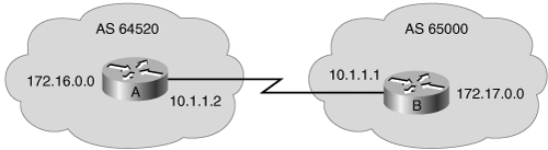
Example 8-12. Configuration of Router A in Figure 8-32
router bgp 64520
  neighbor 10.1.1.1 remote-as 65000
  network 172.16.0.0
Example 8-13. Configuration of Router B in Figure 8-32
router bgp 65000
  neighbor 10.1.1.2 remote-as 64520
  network 172.17.0.0
In this example, Routers A and B define each other as BGP neighbors, and start an EBGP session. Router A advertises the network 172.16.0.0/16, and Router B advertises the network 172.17.0.0/16.
In Figure 8-33, AS 65100 has four routers running IBGP. All of these IBGP neighbors are peering with each others’ loopback 0 interface (shown in the figure) and are using the IP address of their loopback 0 interface as the source IP address for all BGP packets. Each router is using one of its own IP addresses as the next-hop address for each network advertised through BGP. These are outbound policies.

Example 8-14 shows the configuration of Router C when it is not using a peer group.
Example 8-14. Configuration of Router C in Figure 8-33 Without Using a Peer Group
router bgp 65100
  neighbor 192.168.24.1 remote-as 65100
  neighbor 192.168.24.1 update-source loopback 0
  neighbor 192.168.24.1 next-hop-self
  neighbor 192.168.24.1 distribute-list 20 out
  neighbor 192.168.25.1 remote-as 65100
  neighbor 192.168.25.1 update-source loopback 0
  neighbor 192.168.25.1 next-hop-self
  neighbor 192.168.25.1 distribute-list 20 out
  neighbor 192.168.26.1 remote-as 65100
  neighbor 192.168.26.1 update-source loopback 0
  neighbor 192.168.26.1 next-hop-self
  neighbor 192.168.26.1 distribute-list 20 out
Router C has an outbound distribution list associated with each IBGP neighbor. This outbound filter performs the same function as the distribute-list command you use for internal routing protocols; however, when used for BGP, it is linked to a specific neighbor. For example, the ISP behind Router C might be announcing private address space to Router C, and Router C does not want to pass these networks to other routers running BGP in AS 65100.
To accomplish this, access-list 20 might look like the following:
access-list 20 deny 10.0.0.0 0.255.255.255
access-list 20 deny 172.16.0.0 0.31.255.255
access-list 20 deny 192.168.0.0 0.0.255.255
access-list 20 permit any
As shown in Example 8-14, all IBGP neighbors have the outbound distribution list linked to them individually. If Router C receives a change from AS 65101, it must generate an individual update for each IBGP neighbor and run each update against distribute-list 20. If Router C has a large number of IBGP neighbors, the processing power needed to inform the IBGP neighbors of the changes in AS 65101 could be extensive.
Example 8-15 shows the configuration of Router C when it is using a peer group called internal. The neighbor remote-as, neighbor update-source, neighbor next-hop-self, and neighbor distribute-list 20 out commands are all linked to peer group internal, which in turn is linked to each of the IBGP neighbors. If Router C receives a change from AS 65101, it creates a single update and processes it through distribute-list 20 once. The update is replicated for each neighbor that is part of the internal peer group. This action saves processing time in generating the updates for all IBGP neighbors. Thus, the use of peer groups can improve efficiency when processing updates for BGP neighbors that have a common outbound BGP policy.
Example 8-15. Configuration of Router C in Figure 8-33 Using a Peer Group
router bgp 65100
  neighbor internal peer-group
  neighbor internal remote-as 65100
  neighbor internal update-source loopback 0
  neighbor internal next-hop-self
  neighbor internal distribute-list 20 out
  neighbor 192.168.24.1 peer-group internal
  neighbor 192.168.25.1 peer-group internal
  neighbor 192.168.26.1 peer-group internal
Adding a new neighbor with the same policies as the other IBGP neighbors to Router C when it is using a peer group requires adding only a single neighbor statement to link the new neighbor to the peer group. Adding that same neighbor to Router C if it does not use a peer group requires four neighbor statements.
Using a peer group also makes the configuration easier to read and change. If you need to add a new policy, such as a route map, to all IBGP neighbors on Router C, and you are using a peer group, you need only to link the route map to the peer group. If Router C does not use a peer group, you need to add the new policy to each neighbor.
Figure 8-34 shows another BGP example.

Example 8-16 shows the configuration for Router B in Figure 8-34 (note that line numbers have been added to this example to simplify the discussion). The first two commands under the router bgp 65000 command establish that Router B has the following two BGP neighbors:
Router A in AS 64520
Router C in AS 65000
Example 8-16. Configuration of Router B in Figure 8-34
1.    router bgp 65000
2.    neighbor 10.1.1.2 remote-as 64520
3.    neighbor 192.168.2.2 remote-as 65000
4.    neighbor 192.168.2.2 update-source loopback 0
5.    neighbor 192.168.2.2 next-hop-self
6.    network 172.16.10.0 mask 255.255.255.0
7.    network 192.168.1.0
8.    network 192.168.3.0
9.    no synchronization
From the perspective of Router B, Router A is an EBGP neighbor, and Router C is an IBGP neighbor.
The neighbor statement on Router B for Router A is pointing to the directly connected IP address to reach Router A. However, the neighbor statement on Router B for Router C points to Router C’s loopback interface. Router B has multiple paths to reach Router C. If Router B pointed to the 192.168.3.2 IP address of Router C and that interface went down, Router B would be unable to reestablish the BGP session until the link came back up. By pointing to the loopback interface of Router C, the link stays established as long as any path to Router C is available. (Router C should also point to Router B’s loopback address in its configuration.)
Line 4 in the configuration forces Router B to use its loopback 0 address, 192.168.2.1, as the source IP address when sending an update to Router C, 192.168.2.2.
In line 5, Router B changes the next-hop address for networks that can be reached through it. The default next-hop for networks from AS 64520 is 10.1.1.2. With the neighbor next-hop-self command, Router B sets the next-hop address to the source IP address of the routing update, which is Router B’s loopback 0 address, as set by the neighbor update-source command.
Lines 6, 7, and 8 tell BGP which networks to advertise. Line 6 contains a subnet of a Class B address using the mask option. Lines 7 and 8 contain two network statements for the two Class C networks that connect Routers B and C. The default mask for these networks is 255.255.255.0, so it is not needed in the commands.
In line 9, synchronization is disabled (this command is not needed if the router is running Cisco IOS Software Release 12.2(8)T or later, because then synchronization is off by default). If Router A is advertising 172.20.0.0 in BGP, Router B receives that route and advertises it to Router C. Because synchronization is off, Router C can use this route. If Router C had EBGP neighbors of its own and Router B wanted to use Router C as the path to those networks, synchronization on Router B would also need to be off. In this network, synchronization can be off because all the routers within the transit path in AS are running IBGP.
You can verify BGP operation using show EXEC commands, including the following:
show ip bgp—. Displays entries in the BGP topology database (BGP table). Specify a network number to get more specific information about a particular network.
show ip bgp rib-failure—. Displays BGP routes that were not installed in the routing information base (RIB), and the reason that they were not installed.
show ip bgp neighbors—. Displays detailed information about the TCP and BGP connections to neighbors.
show ip bgp summary—. Displays the status of all BGP connections.
Use the show ip bgp? command on a router to see other BGP show commands.
debug commands display events as they happen on the router. For BGP, the debug ip bgp privileged EXEC command has many options, including the following:
dampening—. BGP dampening
events—. BGP events
keepalives—. BGP keepalives
updates—. BGP updates
The following sections provide sample output for some of these commands.
Use the show ip bgp command to display the BGP topology database (the BGP table).
Example 8-17 is a sample output for the show ip bgp command. The status codes are shown at the beginning of each line of output, and the origin codes are shown at the end of each line. In this output, most of the rows have an asterisk (*) in the first column. This means that the next-hop address (in the fifth column) is valid. The next-hop address is not always the router that is directly connected to this router. Other options for the first column are as follows:
An s indicates that the specified routes are suppressed (usually because routes have been summarized and only the summarized route is being sent).
A d, for dampening, indicates that the route is being dampened (penalized) for going up and down too often. Although the route might be up right now, it is not advertised until the penalty has expired.
An h, for history, indicates that the route is unavailable and is probably down; historic information about the route exists, but a best route does not exist.
An r, for RIB failure, indicates that the route was not installed in the RIB. The reason that the route is not installed can be displayed using the show ip bgp rib-failure command, as described in the next section.
An S, for stale, indicates that the route is stale (this is used in a nonstop forwarding-aware router).
Example 8-17. show ip bgp Command Output
RouterA#show ip bgp
BGP table version is 14, local router ID is 172.31.11.1
Status codes: s suppressed, d damped, h history, * valid, > best, i - internal, r RIB-
  failure, S Stale
Origin codes: i - IGP, e - EGP, ? - incomplete
   Network          Next Hop            Metric LocPrf Weight Path
*> 10.1.0.0/24      0.0.0.0                  0         32768 i
* i                 10.1.0.2                 0    100      0 i
*> 10.1.1.0/24      0.0.0.0                  0         32768 i
*>i10.1.2.0/24      10.1.0.2                 0    100      0 i
*> 10.97.97.0/24    172.31.1.3                             0 64998 64997 i
*                   172.31.11.4                            0 64999 64997 i
* i                 172.31.11.4              0    100      0 64999 64997 i
*> 10.254.0.0/24    172.31.1.3               0             0 64998 i
*                   172.31.11.4                            0 64999 64998 i
* i                 172.31.1.3               0    100      0 64998 i
r> 172.31.1.0/24    172.31.1.3               0             0 64998 i
r                   172.31.11.4                            0 64999 64998 i
r i                 172.31.1.3               0    100      0 64998 i
*> 172.31.2.0/24    172.31.1.3               0             0 64998 i
<output omitted>
A greater-than sign (>) in the second column indicates the best path for a route selected by BGP; this route is offered to the IP routing table.
The third column is either blank or has an i in it. If it is blank, BGP learned that route from an external peer. If it has an i, an IBGP neighbor advertised this route to this router.
The fourth column lists the networks that the router learned.
The fifth column lists all the next-hop addresses for each route. This next-hop address column might contain 0.0.0.0, which signifies that this router originated the route.
The next three columns list three BGP path attributes associated with the path: metric (MED), local preference, and weight.
The column with the “Path” header may contain a sequence of autonomous systems in the path. From left to right, the first AS listed is the adjacent AS from which this network was learned. The last number (the rightmost AS number) is this network’s originating AS. The AS numbers between these two represent the exact path that a packet takes back to the originating AS. If the path column is blank, the route is from the current AS.
The last column signifies how this route was entered into BGP on the original router (the origin attribute). If the last column has an i in it, the original router probably used a network command to introduce this network into BGP. The character e signifies that the original router learned this network from EGP, which is the historic predecessor to BGP. A question mark (?) signifies that the original BGP process cannot absolutely verify this network’s availability, because it is redistributed from an IGP into the BGP process.
Use the show ip bgp rib-failure command to display BGP routes that were not installed in the RIB, and the reason that they were not installed. In Example 8-18 the displayed routes were not installed because a route or routes with a better administrative distance already existed in the RIB.
The show ip bgp summary command is one way to verify the BGP neighbor relationship. Example 8-19 presents sample output from this command. Here are some of the highlights:
BGP router identifier—. IP address that all other BGP speakers recognize as representing this router.
BGP table version—. Increases in increments when the BGP table changes.
Main Routing table version—. Last version of BGP database that was injected into the main routing table.
Neighbor—. The IP address, used in the neighbor statement, with which this router is setting up a relationship.
Version (V)—. The version of BGP this router is running with the listed neighbor.
AS—. The listed neighbor’s AS number.
Messages received (MsgRcvd)—. The number of BGP messages received from this neighbor.
Messages sent (MsgSent)—. The number of BGP messages sent to this neighbor.
TblVer—. The last version of the BGP table that was sent to this neighbor.
In queue (InQ)—. The number of messages from this neighbor that are waiting to be processed.
Out queue (OutQ)—. The number of messages queued and waiting to be sent to this neighbor. TCP flow control prevents this router from overwhelming a neighbor with a large update.
Up/Down—. The length of time this neighbor has been in the current BGP state (established, active, or idle).
State—. The current state of the BGP session—active, idle, open sent, open confirm, or idle (admin). The admin state is new to Cisco IOS Software Release 12.0; it indicates that the neighbor is administratively shut down. This state is created by using the neighbor ip-address shutdown router configuration command. (Neighbor states are discussed in more detail in the “Understanding and Troubleshooting BGP Neighbor States” section later in this chapter.) Note that if the session is in the established state, a state is not displayed; instead, a number representing the PfxRcd is displayed, as described next.
Prefix received (PfxRcd)—. When the session is in the established state, this value represents the number of BGP network entries received from this neighbor.
Example 8-19. show ip bgp summary Command Output
RouterA#show ip bgp summary
BGP router identifier 10.1.1.1, local AS number 65001
BGP table version is 124, main routing table version 124
9 network entries using 1053 bytes of memory
22 path entries using 1144 bytes of memory
12/5 BGP path/bestpath attribute entries using 1488 bytes of memory
6 BGP AS-PATH entries using 144 bytes of memory
0 BGP route-map cache entries using 0 bytes of memory
0 BGP filter-list cache entries using 0 bytes of memory
BGP using 3829 total bytes of memory
BGP activity 58/49 prefixes, 72/50 paths, scan interval 60 secs

Neighbor     V    AS MsgRcvd MsgSent   TblVer  InQ OutQ Up/Down  State/PfxRcd

10.1.0.2     4 65001      11      11      124    0    0 00:02:28        8
172.31.1.3   4 64998      21      18      124    0    0 00:01:13        6
172.31.11.4  4 64999      11      10      124    0    0 00:01:11        6
Note
Example output of the show ip bgp neighbors command is provided in the “Understanding and Troubleshooting BGP Neighbor States” section later in this chapter.
Example 8-20 shows partial output from the debug ip bgp updates command on Router A after the clear ip bgp command is issued to clear BGP sessions with its IBGP neighbor 10.1.0.2.
Example 8-20. debug ip bgp updates Command Output
RouterA#debug ip bgp updates
Mobile router debugging is on for address family: IPv4 Unicast
RouterA#clear ip bgp 10.1.0.2
<output omitted>
*May 24 11:06:41.309: %BGP-5-ADJCHANGE: neighbor 10.1.0.2 Up
*May 24 11:06:41.309: BGP(0): 10.1.0.2 send UPDATE (format) 10.1.1.0/24, next 10.1.0.1,
   metric 0, path Local
*May 24 11:06:41.309: BGP(0): 10.1.0.2 send UPDATE (prepend, chgflags: 0x0) 10.1.0.0/24,
   next 10.1.0.1, metric 0, path Local
*May 24 11:06:41.309: BGP(0): 10.1.0.2 NEXT_HOP part 1 net 10.97.97.0/24, next 172.31.11.4
*May 24 11:06:41.309: BGP(0): 10.1.0.2 send UPDATE (format) 10.97.97.0/24, next
   172.31.11.4, metric 0, path 64999 64997
*May 24 11:06:41.309: BGP(0): 10.1.0.2 NEXT_HOP part 1 net 172.31.22.0/24, next 172.31.11.4
*May 24 11:06:41.309: BGP(0): 10.1.0.2 send UPDATE (format) 172.31.22.0/24, next
   172.31.11.4, metric 0, path 64999
<output omitted>
*May 24 11:06:41.349: BGP(0): 10.1.0.2 rcvd UPDATE w/ attr: nexthop 10.1.0.2, origin i,
   localpref 100, metric 0
*May 24 11:06:41.349: BGP(0): 10.1.0.2 rcvd 10.1.2.0/24
*May 24 11:06:41.349: BGP(0): 10.1.0.2 rcvd 10.1.0.0/24
After the neighbor adjacency is reestablished, Router A creates and sends updates to 10.1.0.2. The first update highlighted in the example, 10.1.1.0/24, next 10.1.0.1, is an update about network 10.1.1.0/24, with a next hop of 10.1.0.1, which is Router A’s address. The second update highlighted in the example, 10.97.97.0/24, next 172.31.11.4, is an update about network 10.97.97.0/24, with a next hop of 172.31.11.4, which is the address of one of Router A’s EBGP neighbors. The EBGP next-hop address is being carried into IBGP.
Router A later receives updates from 10.1.0.2. The update highlighted in the example contains a path to two networks, 10.1.2.0/24 and 10.1.0.0/24.
After the TCP handshake is complete, the BGP application tries to set up a session with the neighbor. BGP is a state machine that takes a router through the following states with its neighbors:
Idle—. The router is searching the routing table to see whether a route exists to reach the neighbor.
Connect—. The router found a route to the neighbor and has completed the three-way TCP handshake.
Open sent—. An open message was sent, with the parameters for the BGP session.
Open confirm—. The router received agreement on the parameters for establishing a session.
Alternatively, the router goes into Active state if there is no response to the open message.
Established—. Peering is established and routing begins.
After you enter the neighbor command, BGP starts in the idle state, and the BGP process checks that it has a route to the IP address listed. BGP should be in the idle state for only a few seconds. If BGP does not find a route to the neighboring IP address, it stays in the idle state. If it finds a route, it goes to the connect state when the TCP handshaking synchronize acknowledge (SYN ACK) packet returns (when the TCP three-way handshake is complete). After the TCP connection is set up, the BGP process creates a BGP open message and sends it to the neighbor. After BGP dispatches this open message, the BGP peering session changes to the open sent state. If there is no response for 5 seconds, the state changes to the active state. If a response does come back in a timely manner, BGP goes to the open confirm state and starts scanning (evaluating) the routing table for the paths to send to the neighbor. When these paths have been found, BGP then goes to the established state and begins routing between the neighbors.
The BGP state is shown in the last column of the show ip bgp summary command output.
Note
You can observe the states that two BGP routers are going through to establish a session using debug commands. In Cisco IOS Software Release 12.4, you can use the debug ip bgp ipv4 unicast command to see this process. In earlier IOS releases, the debug ip bgp events command gave similar output.
Debugging consumes router resources and should be turned on only when necessary.
The idle state indicates that the router does not know how to reach the IP address listed in the neighbor statement. The router is idle for one of the following reasons:
It is waiting for a static route to that IP address or network to be configured.
It is waiting for the local routing protocol (IGP) to learn about this network through an advertisement from another router.
The most common reason for the idle state is that the neighbor is not announcing the IP address or network that the neighbor statement of the router is pointing to. Check the following two conditions to troubleshoot this problem:
Ensure that the neighbor announces the route in its local routing protocol (IGP).
Verify that you have not entered an incorrect IP address in the neighbor statement.
If the router is in the active state, this means that it has found the IP address in the neighbor statement and has created and sent out a BGP open packet but has not received a response (open confirm packet) back from the neighbor.
One common cause of this is when the neighbor does not have a return route to the source IP address. Ensure that the source IP address or network of the packets is advertised into the local routing protocol (IGP) on the neighboring router.
Another common problem associated with the active state is when a BGP router attempts to peer with another BGP router that does not have a neighbor statement peering back at the first router, or the other router is peering with the wrong IP address on the first router. Check to ensure that the other router has a neighbor statement peering at the correct address of the router that is in the active state.
If the state toggles between idle and active, the AS numbers might be misconfigured. You see the following console message at the router with the wrong remote-as number configured in the neighbor statement:
%BGP-3-NOTIFICATION: sent to neighbor 172.31.1.3 2/2 (peer in wrong AS) 2 bytes FDE6
FFFF FFFF FFFF FFFF FFFF FFFF FFFF FFFF 002D 0104 FDE6 00B4 AC1F 0203 1002 0601 0400
  0100 0102 0280 0002 0202 00
At the remote router, you see the following message:
%BGP-3-NOTIFICATION: received from neighbor 172.31.1.1 2/2 (peer in wrong AS) 2 bytes
  FDE6
The established state is the desired state for a neighbor relationship. This state means that both routers agree to exchange BGP updates with one another and routing has begun. If the state column in the show ip bgp summary command output is blank or has a number in it, BGP is in the established state. The number shown is the number of routes that have been learned from this neighbor.
Use the show ip bgp neighbors command to display information about the BGP connections to neighbors. In Example 8-21, the BGP state is established, which means that the neighbors have established a TCP connection and the two peers have agreed to use BGP to communicate.
Example 8-21. show ip bgp neighbors Command Output
RouterA#show ip bgp neighbors
BGP neighbor is 172.31.1.3,  remote AS 64998, external link
  BGP version 4, remote router ID 172.31.2.3
  BGP state = Established, up for 00:19:10
  Last read 00:00:10, last write 00:00:10, hold time is 180, keepalive interval is 60 seconds
  Neighbor capabilities:
    Route refresh: advertised and received(old & new)
    Address family IPv4 Unicast: advertised and received
  Message statistics:
    InQ depth is 0
    OutQ depth is 0
                         Sent       Rcvd
    Opens:                  7          7
    Notifications:          0          0
    Updates:               13         38
<output omitted>
Manipulating path-selection criteria can affect the inbound and outbound traffic policies of an AS. This section discusses path manipulation and how to configure an AS using route maps to manipulate the BGP local preference and MED attributes to influence BGP path selection. This section also describes changing the value of the weight attribute.
Unlike local routing protocols, BGP was never designed to choose the quickest path. Rather, it was designed to manipulate traffic flow to maximize or minimize bandwidth use. Figure 8-35 demonstrates a common situation that can result when using BGP without any policy manipulation.

Using default settings for path selection in BGP might cause uneven use of bandwidth. In Figure 8-35, Router A in AS 65001 is using 60 percent of its outbound bandwidth to Router X in 65004, but Router B is using only 20 percent of its outbound bandwidth. If this utilization is acceptable to the administrator, no manipulation is needed. But if the load averages 60 percent and has temporary bursts above 100 percent of the bandwidth, this situation will cause lost packets, higher latency, and higher CPU usage because of the number of packets being routed. When another link to the same location is available and is not heavily used, it makes sense to divert some of the traffic to the other path. To change outbound path selection from AS 65001, the local preference attribute must be manipulated.
Recall that a higher local preference is preferred. To determine which path to manipulate, the administrator performs a traffic analysis on Internet-bound traffic by examining the most heavily visited addresses, web pages, or domain names. This information can usually be found by examining network management records or firewall accounting information.
Assume that in Figure 8-35, 35 percent of all traffic from AS 65001 has been going to www.cisco.com. The administrator can obtain the Cisco address or AS number by performing a reverse Domain Name System (DNS) lookup or by going to ARIN (at www.arin.net) and looking up the AS number of Cisco Systems or the address space assigned to the company. After this information has been determined, the administrator can use route maps to change the local preference to manipulate path selection for the Cisco network.
Using a route map, Router B can announce, to all routers within AS 65001, all networks associated with the Cisco Systems AS with a higher local preference than Router A announces for those networks. Because routers running BGP prefer routes with the highest local preference, other BGP routers in AS 65001 send all traffic destined for the Cisco Systems AS to exit AS 65001 via Router B. The outbound load for Router B increases from its previous load of 20 percent to account for the extra traffic from AS 65001 destined for the Cisco networks. The outbound load for Router A, which was originally 60 percent, should decrease. This change will make the outbound load on both links more balanced. The administrator should monitor the outbound loads and adjust the configuration accordingly as traffic patterns change over time.
Just as there was a loading issue outbound from AS 65001, there can be a similar problem inbound. For example, if the inbound load to Router B has a much higher utilization than the inbound load to Router A, the BGP MED attribute can be used to manipulate how traffic enters AS 65001. Router A in AS 65001 can announce a lower MED for network 192.168.25.0/24 to AS 65004 than Router B announces. This MED recommends to the next AS how to enter AS 65001. However, MED is not considered until later in the BGP path-selection process than local preference. Therefore, if AS 65004 prefers to leave its AS via Router Y (to Router B in AS 65001), Router Y should be configured to announce a higher local preference to the BGP routers in AS 65004 for network 192.168.25.0/24 than Router X announces. The local preference that Routers X and Y advertise to other BGP routers in AS 65004 is evaluated before the MED coming from Routers A and B. MED is considered a recommendation, because the receiving AS can override it by manipulating another variable that is considered before the MED is evaluated.
As another example using Figure 8-35, assume that 55 percent of all traffic is going to the 192.168.25.0/24 subnet (on Router A). The inbound utilization to Router A is averaging only 10 percent, but the inbound utilization to Router B is averaging 75 percent. The problem is that if the inbound load for Router B spikes to more than 100 percent and causes the link to flap, all the sessions crossing that link could be lost. For example, if these sessions were purchases being made on AS 65001 web servers, revenue would be lost, which is something administrators want to avoid. If AS 65001 were set to prefer to have all traffic that is going to 192.168.25.0/24 enter through Router A, the load inbound on Router A should increase, and the load inbound on Router B should decrease.
If load averages less than 50 percent for an outbound or inbound case, path manipulation might not be needed. However, as soon as a link starts to reach its capacity for an extended period of time, either more bandwidth is needed or path manipulation should be considered. The administrator should monitor the inbound loads and adjust the configuration accordingly as traffic patterns change over time.
An AS rarely implements BGP with only one EBGP connection, so generally multiple paths exist for each network in the BGP forwarding database.
Note
If you are running BGP in a network with only one EBGP connection, it is loop free. If synchronization is disabled or BGP is synchronized with the IGP for IBGP connections, and the next hop can be reached, the path is submitted to the IP routing table. Because there is only path, there is no benefit to manipulating its attributes.
Recall, from the “The Route Selection Decision Process” section earlier in this chapter, that when faced with multiple routes to the same destination, BGP chooses the best route for routing traffic toward the destination. Using the 11-step route selection process, only the best path is put in the routing table and propagated to the router’s BGP neighbors. Without route manipulation, the most common reason for path selection is Step 4, the preference for the shortest AS-path.
Step 1 looks at weight, which by default is set to 0 for routes that were not originated by this router.
Step 2 compares local preference, which by default is set to 100 for all networks. Both of these steps have an effect only if the network administrator configures the weight or local preference to a nondefault value.
Step 3 looks at networks that are owned by this AS. If one of the routes is injected into the BGP table by the local router, the local router prefers it to any routes received from other BGP routers.
Step 4 selects the path that has the fewest autonomous systems to cross. This is the most common reason a path is selected in BGP. If a network administrator does not like the path with the fewest autonomous systems, he or she needs to manipulate weight or local preference to change which outbound path BGP chooses.
Step 5 looks at how a network was introduced into BGP. This introduction is usually either with network statements (i for an origin code) or through redistribution (? for an origin code).
Step 6 looks at MED to judge where the neighbor AS wants this AS to send packets for a given network. The Cisco IOS Software sets the MED to 0 by default; therefore, MED does not participate in path selection unless the network administrator of the neighbor AS manipulates the paths using MED.
If multiple paths have the same number of autonomous systems to traverse, the second most common decision point is Step 7, which states that an externally learned path from an EBGP neighbor is preferred over a path learned from an IBGP neighbor. A router in an AS prefers to use the ISP’s bandwidth to reach a network rather than using internal bandwidth to reach an IBGP neighbor on the other side of its own AS.
If the AS path length is equal and the router in an AS has no EBGP neighbors for that network (only IBGP neighbors), it makes sense to take the quickest path to the nearest exit point. Step 8 looks for the closest IBGP neighbor; the IGP metric determines what closest means (for example, RIP uses hop count, and OSPF uses the least cost, based on bandwidth).
If the AS path length is equal and the costs via all IBGP neighbors are equal, or if all neighbors for this network are EBGP, the oldest path (step 9) is the next common reason for selecting one path over another. EBGP neighbors rarely establish sessions at the exact same time. One session is likely older than another, so the paths through that older neighbor are considered more stable, because they have been up longer.
If all these criteria are equal, the next most common decision is to take the neighbor with the lowest BGP router ID, which is Step 10.
If the BGP router IDs are the same (for example, if the paths are to the same BGP router), Step 11 states that the route with the lowest neighbor IP address is used.
Local preference is used only within an AS between IBGP speakers to determine the best path to leave the AS to reach an outside network. The local preference is set to 100 by default; higher values are preferred.
Note
If for some reason an EBGP neighbor did receive a local preference value (such as because of faulty software), the EBGP neighbor ignores it.
The bgp default local-preference value router configuration command changes the default local preference to the value specified; all BGP routes that are advertised include this local preference value. The value can be set to a number between 0 and 4294967295.
Manipulating the default local preference can have an immediate and dramatic effect on traffic flow leaving an AS. Before making any changes to manipulate paths, the network administrator should perform a thorough traffic analysis to understand the effects of the change. For example, the configurations for Routers A and B in Figure 8-36 are shown in Examples 8-22 and 8-23, respectively. In this network, the administrator changed the default local preference for all routes on Router B to 500 and on Router A to 200. All BGP routers in AS 65001 send all traffic destined for the Internet to Router B, causing its outbound utilization to be much higher and the utilization out Router A to be reduced to a minimal amount. This change is probably not what the network administrator intended. Instead, the network administrator should use route maps to set only certain networks to have a higher local preference through Router B to decrease some of the original outbound load that was being sent out Router A.
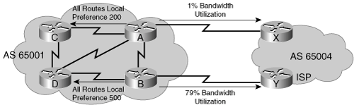
Example 8-22. Configuration for Router A in Figure 8-36
router bgp 65001
  bgp default local-preference 200
Example 8-23. Configuration for Router B in Figure 8-36
router bgp 65001
bgp default local-preference 500Figure 8-37 illustrates a sample network running BGP that will be used to demonstrate how local preference can be manipulated. This network initially has no commands configured to change the local preference.
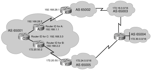
Example 8-24 illustrates the BGP forwarding table on Router C in Figure 8-37, showing only the networks of interest to this example:
172.16.0.0 in AS 65003
172.24.0.0 in AS 65005
172.30.0.0 in AS 65004
Example 8-24. BGP Table for Router C in Figure 8-37 Without Path Manipulation
RouterC#show ip bgp
BGP table version is 7, local router ID is 192.168.3.3
Status codes: s suppressed, d damped, h history, * valid, > best, i - internal,  r RIB-
  failure, S Stale
Origin codes: i - IGP, e - EGP, ? - incomplete
Network             Next Hop      Metric LocPrf  Weight Path
* i172.16.0.0       172.20.50.1             100       0 65005 65004 65003 i
*>i                 192.168.28.1            100       0 65002 65003 i
*>i172.24.0.0       172.20.50.1             100       0 65005 i
* i                 192.168.28.1            100       0 65002 65003 65004 65005 i
*>i172.30.0.0       172.20.50.1             100       0 65005 65004 i
* i                 192.168.28.1            100       0 65002 65003 65004i
The best path is indicated with a > in the second column of the output.
Each network has two paths that are loop-free and synchronization-disabled and that have a valid next-hop address (that can be reached from Router C). All routes have a weight of 0 and a default local preference of 100, so Steps 1 and 2 in the BGP path-selection process do not select the best route.
This router does not originate any of the routes (Step 3), so the process moves to Step 4, and BGP uses the shortest AS-path to select the best routes as follows:
For network 172.16.0.0, the shortest AS-path of two autonomous systems (65002 65003) is through the next hop of 192.168.28.1.
For network 172.24.0.0, the shortest AS-path of one AS (65005) is through the next hop of 172.20.50.1.
For network 172.30.0.0, the shortest AS-path of two autonomous systems (65005 65004) is through the next hop of 172.20.50.1.
Neither Routers A nor B are using the neighbor next-hop-self command in this example.
A traffic analysis reveals the following:
The link going through Router B to 172.20.50.1 is heavily used, and the link through Router A to 192.168.28.1 is hardly used at all.
The three largest-volume destination networks on the Internet from AS 65001 are 172.30.0.0, 172.24.0.0, and 172.16.0.0.
Thirty percent of all Internet traffic is going to network 172.24.0.0 (via Router B), 20 percent is going to network 172.30.0.0 (via Router B), and 10 percent is going to network 172.16.0.0 (via Router A); the other 40 percent is going to other destinations. Thus, considering only these three largest-volume destinations, only 10 percent of the traffic is using the link out Router A to 192.168.28.1, and 50 percent of the traffic is using the link out Router B to 172.20.50.1.
The network administrator has decided to divert traffic to network 172.30.0.0 and send it out Router A to the next hop of 192.168.28.1, so that the loading between Routers A and B is more balanced.
A route map is added to Router A in Figure 8-37, as shown in the BGP configuration in Example 8-25. The route map alters the network 172.30.0.0 BGP update from Router X (192.168.28.1) to have a high local preference value of 400 so that it will be more preferred.
Example 8-25. BGP Configuration for Router A in Figure 8-37 with a Route Map
router bgp 65001
  neighbor 192.168.2.2 remote-as 65001
  neighbor 192.168.3.3 remote-as 65001
  neighbor 192.168.2.2 remote-as 65001 update-source loopback0
  neighbor 192.168.3.3 remote-as 65001 update-source loopback0
  neighbor 192.168.28.1 remote-as 65002
  neighbor 192.168.28.1 route-map local_pref in
!
route-map local_pref permit 10
  match ip address 65
  set local-preference 400
!
route-map local_pref permit 20
!
access-list 65 permit 172.30.0.0 0.0.255.255
The first line of the route map called local_pref is a permit statement with a sequence number of 10; this defines the first route-map statement. The match condition for this statement checks all networks to see which are permitted by access list 65. Access list 65 permits all networks that start with the first two octets of 172.30.0.0; the route map sets these networks to a local preference of 400.
The second statement in the route map called local_pref is a permit statement with a sequence number of 20, but it does not have any match or set statements. This statement is similar to a permit any statement in an access list. Because there are no match conditions for the remaining networks, they are all permitted with their current settings. In this case, the local preference for networks 172.16.0.0 and 172.24.0.0 stays set at the default of 100. The sequence number 20 (rather than 11) is chosen for the second statement in case other policies have to be implemented later before this permit any statement.
This route map is linked to neighbor 192.168.28.1 as an inbound route map. Therefore, as Router A receives updates from 192.168.28.1, it processes them through the local_pref route map and sets the local preference accordingly as the networks are placed in Router A’s BGP forwarding table.
Example 8-26 illustrates the BGP table on Router C in Figure 8-37, after the route map has been applied on Router A and the BGP sessions have been reset. Router C learns about the new local preference value (400) coming from Router A for network 172.30.0.0. The only difference in this table compared to the original in Example 8-24 is that the best route to network 172.30.0.0 is now through 192.168.28.1 because its local preference of 400 is higher than the local preference of 100 for the next hop of 172.20.50.1. The AS-path through 172.20.50.1 is still shorter than the path through 192.168.28.1, but AS-path length is not evaluated until Step 4, whereas local preference is examined in Step 2. Therefore, the higher local preference path was chosen as the best path.
Example 8-26. BGP Table for Router C in Figure 8-37 with a Route Map for Local Preference
RouterC#show ip bgp
BGP table version is 7, local router ID is 192.168.3.3
Status codes: s suppressed, d damped, h history, * valid, > best, i - internal,  r RIB-
  failure, S Stale
Origin codes: i - IGP, e - EGP, ? - incomplete
   Network          Next Hop       Metric LocPrf Weight Path
* i172.16.0.0       172.20.50.1             100       0 65005 65004 65003 i
*>i                 192.168.28.1            100       0 65002 65003 i
*>i172.24.0.0       172.20.50.1             100       0 65005 i
* i                 192.168.28.1            100       0 65002 65003 65004 65005 i
* i172.30.0.0       172.20.50.1             100       0 65005 65004 i
*>i                 192.168.28.1            400       0 65002 65003 65004i
Recall that MED is used to decide how to enter an AS when multiple paths exist between two autonomous systems and one AS is trying to influence the incoming path from the other AS. Because MED is evaluated late in the BGP path-selection process (Step 6), it usually has no influence on the process. For example, an AS receiving a MED for a route can change its local preference on how to leave the AS to override what the other AS is advertising with its MED value.
When comparing MED values for the same destination network in the BGP path-selection process, the lowest MED value is preferred.
The default MED value for each network an AS owns and advertises to an EBGP neighbor is set to 0. To change this value, use the default-metric number router configuration command. The number parameter is the MED value.
Manipulating the default MED value can have an immediate and dramatic effect on traffic flow entering your AS. Before making any changes to manipulate the path, you should perform a thorough traffic analysis to ensure that you understand the effects of the change.
For example, the configurations of Routers A and B in Figure 8-38 are shown in Examples 8-27 and 8-28, respectively. The network administrator in AS 65001 tries to manipulate how AS 65004 chooses its path to reach routes in AS 65001. By changing the default metric under the BGP process on Router A to 1001, Router A advertises a MED of 1001 for all routes to Router X. Router X then informs all the other routers in AS 65004 of the MED through Router X to reach networks originating in AS 65001. A similar event happens on Router B, but Router B advertises a MED of 99 for all routes to Router Y. All routers in AS 65004 see a MED of 1001 through the next hop of Router A and a MED of 99 through the next hop of Router B to reach networks in AS 65001. (The neighbor next-hop self command is not used on either Router X or Router Y.) If AS 65004 has no overriding policy, all routers in AS 65004 choose to exit their AS through Router Y to reach the networks in AS 65001; this traffic goes through Router B. This selection causes Router A’s inbound bandwidth utilization to decrease to almost nothing except for BGP routing updates, and it causes the inbound utilization on Router B to increase and account for all returning packets from AS 65004 to AS 65001.

This situation is probably not what the network administrator intended. Instead, to load-share the inbound traffic to AS 65001, the AS 65001 network administrator should configure some networks to have a lower MED through Router B and other networks to have a lower MED through Router A. Route maps should be used to set the appropriate MED values for various networks.
The network shown in Figure 8-39 is used as an example to demonstrate how to manipulate inbound traffic using route maps to change the BGP MED attribute. The intention of these route maps is to designate Router A as the preferred entry point to reach networks 192.168.25.0/24 and 192.168.26.0/24 and Router B as the preferred entry point to reach network 192.168.24.0/24. The other networks should still be reachable through each router in case of a link or router failure.

The MED is set outbound when advertising to an EBGP neighbor. In the configuration for Router A shown in Example 8-29, a route map named med_65004 is linked to neighbor 192.168.28.1 (Router X) as an outbound route map. When Router A sends an update to neighbor 192.168.28.1, it processes the outbound update through route map med_65004 and changes any values specified in a set command as long as the corresponding match command conditions in that section of the route map are met.
Example 8-29. BGP Configuration for Router A in Figure 8-39 with a Route Map
router bgp 65001
  neighbor 192.168.2.2 remote-as 65001
  neighbor 192.168.3.3 remote-as 65001
  neighbor 192.168.2.2 update-source loopback0
  neighbor 192.168.3.3 update-source loopback0
  neighbor 192.168.28.1 remote-as 65004
  neighbor 192.168.28.1 route-map med_65004 out
!
route-map med_65004 permit 10
  match ip address 66
  set metric 100
route-map med_65004 permit 100
  set metric 200
!
access-list 66 permit 192.168.25.0.0 0.0.0.255
access-list 66 permit 192.168.26.0.0 0.0.0.255
The first line of the route map called med_65004 is a permit statement with a sequence number of 10; this defines the first route-map statement. The match condition for this statement checks all networks to see which are permitted by access list 66. The first line of access list 66 permits any networks that start with the first three octets of 192.168.25.0, and the second line of access list 66 permits networks that start with the first three octets of 192.168.26.0.
Any networks that are permitted by either of these lines will have the MED set to 100 by the route map. No other networks are permitted by this access list (there is an implicit deny all at the end of all access lists), so their MED is not changed. These other networks must proceed to the next route-map statement in the med_65004 route map.
The route map’s second statement is a permit statement with a sequence number of 100. The route map does not have any match statements, just a set metric 200 statement. This statement is a permit any statement for route maps. Because the network administrator does not specify a match condition for this portion of the route map, all networks being processed through this section of the route map (sequence number 100) are permitted, and they are set to a MED of 200. If the network administrator did not set the MED to 200, by default it would have been set to a MED of 0. Because 0 is less than 100, the routes with a MED of 0 would have been the preferred paths to the networks in AS 65001.
Similarly, the configuration for Router B is shown in Example 8-30. A route map named med_65004 is linked to neighbor 172.20.50.1 as an outbound route map. Before Router B sends an update to neighbor 172.20.50.1, it processes the outbound update through route map med_65004, and changes any values specified in a set command as long as the preceding match command conditions in that section of the route map are met.
Example 8-30. BGP Configuration for Router B in Figure 8-39 with a Route Map
router bgp 65001
  neighbor 192.168.1.1 remote-as 65001
  neighbor 192.168.3.3 remote-as 65001
  neighbor 192.168.1.1 update-source loopback0
  neighbor 192.168.3.3 update-source loopback0
  neighbor 172.20.50.1 remote-as 65004
  neighbor 172.20.50.1 route-map med_65004 out
!
route-map med_65004 permit 10
  match ip address 66
  set metric 100
route-map med_65004 permit 100
  set metric 200
!
access-list 66 permit 192.168.24.0.0 0.0.0.255
The first line of the route map called med_65004 is a permit statement with a sequence number of 10; this defines the first route-map statement. The match condition for this statement checks all networks to see which are permitted by access list 66. Access list 66 on Router B permits any networks that start with the first three octets of 192.168.24.0. Any networks that are permitted by this line have the MED set to 100 by the route map. No other networks are permitted by this access list, so their MED is unchanged. These other networks must proceed to the next route-map statement in the med_65004 route map.
The second statement of the route map is a permit statement with a sequence number of 100, but it does not have any match statements, just a set metric 200 statement. This statement is a permit any statement for route maps. Because the network administrator does not specify a match condition for this portion of the route map, all networks being processed through this section of the route map are permitted, but they are set to a MED of 200. If the network administrator did not set the MED to 200, by default it would have been set to a MED of 0. Because 0 is less than 100, the routes with a MED of 0 would have been the preferred paths to the networks in AS 65001.
Example 8-31 shows the BGP forwarding table on Router Z in AS 65004 indicating the networks learned from AS 65001. (Other networks that do not affect this example have been omitted.) Note that in this command output, the MED is shown in the column labeled Metric.
Example 8-31. BGP Table for Router Z in Figure 8-39 with a Route Map
RouterZ#show ip bgp
BGP table version is 7, local router ID is 192.168.1.1
Status codes: s suppressed, d damped, h history, * valid, > best, i - internal,  r RIB-
   failure, S Stale
Origin codes: i - IGP, e - EGP, ? - incomplete
   Network          Next Hop       Metric LocPrf Weight Path
*>i192.168.24.0     172.20.50.2      100    100       0 65001 i
* i                 192.168.28.2     200    100       0 65001 i
* i192.168.25.0     172.20.50.2      200    100       0 65001 i
*>i                 192.168.28.2     100    100       0 65001 i
* i192.168.26.0     172.20.50.2      200    100       0 65001 i
*>i                 192.168.28.2     100    100       0 65001 i
Router Z has multiple paths to reach each network. These paths all have valid next-hop addresses and synchronization disabled and are loop free. All networks have a weight of 0 and a local preference of 100, so Steps 1 and 2 in the route-selection decision process do not determine the best path. None of the routes were originated by this router or any router in AS 65004; all networks came from AS 65001, so Step 3 does not apply. All networks have an AS-path of one AS (65001) and were introduced into BGP with network statements (i is the origin code), so Steps 4 and 5 are equal. The route selection decision process therefore gets to Step 6, which states that BGP chooses the lowest MED if all preceding steps are equal or do not apply.
For network 192.168.24.0, the next hop of 172.20.50.2 has a lower MED than the next hop of 192.168.28.2. Therefore, for network 192.168.24.0, the path through 172.20.50.2 is the preferred path. For networks 192.168.25.0 and 192.168.26.0, the next hop of 192.168.28.2 has a lower MED (100) than the next hop of 172.20.50.2 (with a MED of 200). Therefore, 192.168.28.2 is the preferred path for those two networks.
Recall that the weight attribute influences only the local router. Routes with a higher weight are preferred.
The neighbor {ip-address | peer-group-name} weight weight router configuration command is used to assign a weight to updates from a neighbor connection, as described in Table 8-8.
Figure 8-40 depicts a typical enterprise BGP implementation. The enterprise is multihomed to two ISPs, to increase the reliability and performance of its connection to the Internet. The ISPs might pass only default routes or might also pass other specific routes, or even all routes, to the enterprise. The enterprise routers connected to the ISPs run EBGP with the ISP routers and IBGP between themselves; thus all routers in the transit path within the enterprise AS run IBGP. These routers pass default routes to the other routers in the enterprise, rather than redistributing BGP into the interior routing protocol.
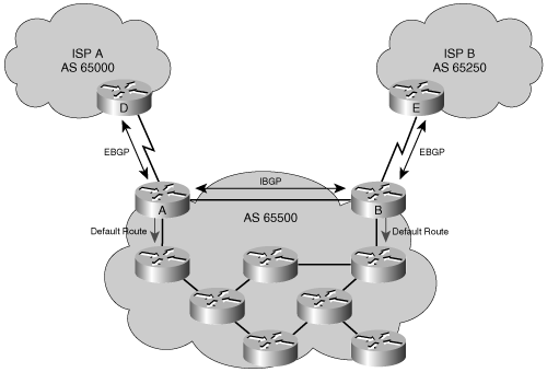
BGP attributes can be manipulated, using the methods discussed in this section, by any of the routers running BGP, to affect the path of the traffic to and from the autonomous systems.
This chapter covered the basics of BGP, the EGP used on the Internet, through discussion of the following topics:
BGP terminology and concepts, including BGP’s use between autonomous systems, BGP neighbor relationships and the difference between IBGP and EBGP, multihoming options, when to use BGP and when not to use BGP, BGP’s use of TCP, and the use of IBGP on all routers in the transit path within the AS.
The three tables used by BGP: the BGP table, IP routing table, and BGP neighbor table.
The four BGP message types: open, keepalive, update, and notification.
The BGP attributes that can be either well-known or optional, mandatory or discretionary, and transitive or nontransitive; an attribute might also be partial. The BGP attributes are AS-path, next-hop, origin, local preference, atomic aggregate, aggregator, community, MED, and the Cisco-defined weight.
The 11-step route selection decision process.
BGP configuration, verification and troubleshooting commands and examples, including BGP neighbor authentication.
Understanding and troubleshooting the BGP states: idle, connect, active, open sent, open confirm, and established.
BGP path manipulation using route maps, including changing the local preference and MED attributes.
For additional information, refer to Cisco’s command reference and configuration guides available from the Documentation DVD home page at http://www.cisco.com/univercd/cc/td/doc/.
In this Configuration Exercise, you configure EBGP between your PxR1 and PxR2 routers and the two backbone routers, BBR1 and BBR2.
Note
Throughout this exercise, the pod number is referred to as x, and the router number is referred to as y. Substitute the appropriate numbers as needed.
The objectives of this exercise are to configure EBGP on your edge routers which are multihomed to the backbone, to simulate multihomed ISP connections.
Figure 8-41 illustrates the topology used and what you will accomplish in this exercise.
In this exercise, you use the commands in Table 8-9, listed in logical order. Refer to this list if you need configuration command assistance during the exercise.
Table 8-9. Multihomed BGP Configuration Exercise Commands
Command | Description |
|---|---|
(config)#router bgp 6500x | Enters BGP router configuration mode. This router is in AS 6500x. |
(config-router)#neighbor 10.200.200.xy remote-as 6500x | Identifies a BGP neighbor. |
(config-router)#neighbor 10.200.200.xy update-source loopback 0 | Sets the source address of BGP updates with the neighbor to be the address of the loopback 0 interface. |
(config-router)#network 10.x.0.0 mask 255.255.255.0 | Advertises a network in BGP. |
#show ip bgp summary | Displays a summary of BGP neighbor status and activities. |
#show ip bgp | Displays the BGP table. |
#show ip route | Displays the IP routing table. |
(config-router)#passive-interface s0/0/1 | Configures a routing protocol not to send updates or hellos out the specified interface. |
#show ip protocols | Displays a summary of the IP routing protocols running on the router. |
In this task, you remove some of the configuration from the previous exercises, and create two multipoint subinterfaces on your edge routers in preparation for configuring BGP in the next task. Follow these steps:
Connect to each of your pod edge routers (PxR1 and PxR2). Remove all OSPF configurations from these edge routers, but leave RIPv2 enabled on them.
Remove any route maps and access lists that were configured on the edge routers in the previous exercises.
On the edge routers, shut down interface s0/0/0 and remove all configuration commands on that interface by using the default interface s0/0/0 global configuration command.
Note
If your edge routers have not been reloaded in the Configuration Exercises in Chapter 7, you have to save your configuration and then reload your edge routers after using the default interface s0/0/0 command. Even though this command deletes the s0/0/0 subinterfaces, it does not remove the subinterface configuration from the router’s memory, and you will not be able to change the link type of the s0/0/0.2 subinterface (from point-to-point to multipoint) until the router has been reloaded.
Solution:
The following shows the required steps on the P1R1 router:
P1R1(config)#no router ospf 1
P1R1(config)#no route-map CONVERT
P1R1(config)#no access-list 61
P1R1(config)#no access-list 64
P1R1(config)#default interface s0/0/0
Building configuration...

Interface Serial0/0/0 set to default configuration
P1R1(config)#

P1R1#copy run start
Destination filename [startup-config]?
Building configuration...
[OK]
P1R1#reload
Proceed with reload? [confirm]
On the edge routers’ s0/0/0 interface, enable Frame Relay encapsulation, and then disable Frame Relay Inverse Address Resolution Protocol (ARP).
Create two multipoint subinterfaces on each edge router’s serial 0/0/0 interface. These subinterfaces will be used to connect to both core routers (BBR1 and BBR2) in this exercise.
Configure subinterface s0/0/0.1 with an IP address of 172.31.x.y/24 and a Frame Relay map statement pointing to the BBR1 address of 172.31.x.3; do not forget the broadcast option. PxR1 uses DLCI 1x1 and PxR2 uses DLCI 1x2 to reach 172.31.x.3/24.
Configure the second subinterface, s0/0/0.2, with an IP address of 172.31.xx.y/24 and a Frame Relay map statement pointing to the BBR2 address of 172.31.xx.4; do not forget the broadcast option. PxR1 uses DLCI 2x1 and PxR2 uses DLCI 2x2 to reach 172.31.xx.4/24.
Enable interface s0/0/0 on the edge routers.
Solution:
The following shows the required steps on the P1R1 router:
P1R1(config)#int s0/0/0
P1R1(config-if)#encapsulation frame-relay
P1R1(config-if)#no frame-relay inverse-arp
P1R1(config-if)#int s0/0/0.1 multipoint
P1R1(config-subif)#ip address 172.31.1.1 255.255.255.0
P1R1(config-subif)#frame-relay map ip 172.31.1.3 111 broadcast
P1R1(config-subif)#int s0/0/0.2 multipoint
P1R1(config-subif)#ip address 172.31.11.1 255.255.255.0
P1R1(config-subif)#frame-relay map ip 172.31.11.4 211 broadcast
P1R1(config-subif)#int s0/0/0
P1R1(config-if)#no shutdown
Test each subinterface by pinging the BBR1 and BBR2 routers from both edge routers.
Solution:
The following shows sample output on the P1R1 router:
P1R1#ping 172.31.1.3

Type escape sequence to abort.
Sending 5, 100-byte ICMP Echos to 172.31.1.3, timeout is 2 seconds:
!!!!!
Success rate is 100 percent (5/5), round-trip min/avg/max = 28/30/32 ms
P1R1#ping 172.31.11.4

Type escape sequence to abort.
Sending 5, 100-byte ICMP Echos to 172.31.11.4, timeout is 2 seconds:
!!!!!
Success rate is 100 percent (5/5), round-trip min/avg/max = 28/29/32 ms
P1R1#
In this task, you configure basic BGP on the edge routers. Follow these steps:
Configure BGP on the edge routers in the pod (PxR1 and PxR2) using AS 6500x, where x is the pod number.
Configure PxR1 and PxR2 with two EBGP neighbors, BBR1 (in AS 64998) and BBR2 (in AS 64999), and as IBGP neighbors to each other. BBR1 has IP address 172.31.x.3, and BBR2 has IP address 172.31.xx.4. Use the loopback addresses (10.200.200.xy) to establish the IBGP session between the two edge routers, and remember to configure the loopbacks as the source address of the IBGP updates.
Configure the edge routers to advertise your pod networks 10.x.0.0/24, 10.x.1.0/24, 10.x.2.0/24, and 10.x.3.0/24 to the core routers. There are two points to remember:
The 10.0.0.0 network is subnetted, so you need to use the mask option of the network command to announce the subnets.
The networks listed in the network command must match the networks in the routing table exactly.
Solution:
The following shows the required steps on the P1R1 router:
P1R1(config)#router bgp 65001
P1R1(config-router)#neighbor 172.31.1.3 remote-as 64998
P1R1(config-router)#neighbor 172.31.11.4 remote-as 64999
P1R1(config-router)#neighbor 10.200.200.12 remote-as 65001
P1R1(config-router)#neighbor 10.200.200.12 update-source loop 0
P1R1(config-router)#network 10.1.0.0 mask 255.255.255.0
P1R1(config-router)#network 10.1.1.0 mask 255.255.255.0
P1R1(config-router)#network 10.1.2.0 mask 255.255.255.0
P1R1(config-router)#network 10.1.3.0 mask 255.255.255.0
At the edge routers, verify that all three BGP neighbor relationships are established using the show ip bgp summary command.
Do you see one IBGP neighbor and two EBGP neighbors on each edge router?
How many prefixes have been learned from each BGP neighbor?
Solution:
The following shows sample output on the P1R1 router. Each router has one IBGP neighbor and two EBGP neighbors. The number in the State/PfxRcd column indicates the number of prefixes received from the neighbor; the presence of a number in that column indicates that the BGP session with that neighbor is in the established state.
P1R1#show ip bgp summary
BGP router identifier 10.200.200.11, local AS number 65001
BGP table version is 13, main routing table version 13
10 network entries using 1170 bytes of memory
25 path entries using 1300 bytes of memory
14/5 BGP path/bestpath attribute entries using 1736 bytes of memory
6 BGP AS-PATH entries using 144 bytes of memory
0 BGP route-map cache entries using 0 bytes of memory
0 BGP filter-list cache entries using 0 bytes of memory
BGP using 4350 total bytes of memory
BGP activity 10/0 prefixes, 25/0 paths, scan interval 60 secs

Neighbor        V    AS MsgRcvd MsgSent   TblVer  InQ OutQ Up/Down  State/PfxRcd

10.200.200.12   4 65001      12      11       13    0    0 00:01:59        9
172.31.1.3      4 64998      17      14       13    0    0 00:04:58        6
172.31.11.4     4 64999      19      14       13    0    0 00:04:51        6
P1R1#
At the edge routers, display the BGP table. Verify that you have received routes from the core and from the other edge router. Look at the IP routing table on the edge routers. Are the BGP routes present?
Solution:
The following shows sample output on the P1R1 router. P1R1 has received routes from all three of its neighbors.
P1R1#show ip bgp
BGP table version is 13, local router ID is 10.200.200.11
Status codes: s suppressed, d damped, h history, * valid, > best, i - internal,
              r RIB-failure, S Stale
Origin codes: i - IGP, e - EGP, ? - incomplete

   Network          Next Hop            Metric LocPrf Weight Path
* i10.1.0.0/24      10.200.200.12            0    100      0 i
*>                  0.0.0.0                  0         32768 i
*> 10.1.1.0/24      0.0.0.0                  0         32768 i
* i10.1.2.0/24      10.200.200.12            0    100      0 i
*>                  10.1.0.2                 1         32768 i
* i10.1.3.0/24      10.1.2.4                 1    100      0 i
*>                  10.1.1.3                 1         32768 i
* i10.97.97.0/24    172.31.1.3               0    100      0 64998 64997 i
*                   172.31.11.4                            0 64999 64997 i
*>                  172.31.1.3                             0 64998 64997 i
* i10.254.0.0/24    172.31.1.3               0    100      0 64998 i
*                   172.31.11.4                            0 64999 64998 i
*>                  172.31.1.3               0             0 64998 i
r i172.31.1.0/24    172.31.1.3               0    100      0 64998 i
r                   172.31.11.4                            0 64999 64998 i
r>                  172.31.1.3               0             0 64998 i
* i172.31.2.0/24    172.31.1.3               0    100      0 64998 i
*                   172.31.11.4                            0 64999 64998 i
*>                  172.31.1.3               0             0 64998 i
r i172.31.11.0/24   172.31.11.4              0    100      0 64999 i
r>                  172.31.11.4              0             0 64999 i
r                   172.31.1.3                             0 64998 64999 i
* i172.31.22.0/24   172.31.11.4              0    100      0 64999 i
*>                  172.31.11.4              0             0 64999 i
*                   172.31.1.3                             0 64998 64999 i
P1R1#
The following shows sample output on the P1R1 router. There are BGP routes in the IP routing table.
P1R1#show ip route
<output omitted>
Gateway of last resort is 172.31.11.4 to network 0.0.0.0

     172.31.0.0/24 is subnetted, 4 subnets
B       172.31.22.0 [20/0] via 172.31.11.4, 00:13:46
B       172.31.2.0 [20/0] via 172.31.1.3, 00:13:46
C       172.31.1.0 is directly connected, Serial0/0/0.1
C       172.31.11.0 is directly connected, Serial0/0/0.2
     10.0.0.0/8 is variably subnetted, 10 subnets, 2 masks
C       10.200.200.11/32 is directly connected, Loopback0
R       10.200.200.14/32 [120/2] via 10.1.1.3, 00:00:07, FastEthernet0/0
                         [120/2] via 10.1.0.2, 00:00:18, Serial0/0/1
R       10.200.200.12/32 [120/1] via 10.1.0.2, 00:00:19, Serial0/0/1
R       10.200.200.13/32 [120/1] via 10.1.1.3, 00:00:08, FastEthernet0/0
R       10.1.3.0/24 [120/1] via 10.1.1.3, 00:00:08, FastEthernet0/0
R       10.1.2.0/24 [120/1] via 10.1.0.2, 00:00:19, Serial0/0/1
B       10.97.97.0/24 [20/0] via 172.31.1.3, 00:13:48
C       10.1.1.0/24 is directly connected, FastEthernet0/0
C       10.1.0.0/24 is directly connected, Serial0/0/1
B       10.254.0.0/24 [20/0] via 172.31.1.3, 00:13:48
S*   0.0.0.0/0 [1/0] via 172.31.11.4
P1R1#
Telnet to the core routers, BBR1 (172.31.x.3) and BBR2 (172.31.xx.4). Look at the IP routing table. Are the BGP routes present for your pod? Exit the Telnet sessions.
Solution:
The following shows sample output on the BBR1 and BBR2 routers. The routes from pod 1 are highlighted.
BBR1#show ip route
<output omitted>
Gateway of last resort is not set

     172.31.0.0/24 is subnetted, 4 subnets
B       172.31.22.0 [20/0] via 10.254.0.2, 2w5d
C       172.31.2.0 is directly connected, Serial0/0/0.2
C       172.31.1.0 is directly connected, Serial0/0/0.1
B       172.31.11.0 [20/0] via 10.254.0.2, 00:33:01
S    192.168.11.0/24 [1/0] via 172.31.1.2
     10.0.0.0/24 is subnetted, 6 subnets
B       10.1.3.0 [20/1] via 172.31.1.2, 00:18:00
B       10.1.2.0 [20/0] via 172.31.1.2, 00:18:00
B       10.97.97.0 [20/0] via 10.254.0.3, 2w5d
B       10.1.1.0 [20/0] via 172.31.1.1, 00:19:49
B       10.1.0.0 [20/0] via 172.31.1.1, 00:20:20
C       10.254.0.0 is directly connected, FastEthernet0/0
S    192.168.22.0/24 [1/0] via 172.31.2.2
S    192.168.1.0/24 [1/0] via 172.31.1.1
S    192.168.2.0/24 [1/0] via 172.31.2.1
BBR1#

BBR2#show ip route
<output omitted>
Gateway of last resort is not set

     172.31.0.0/24 is subnetted, 4 subnets
C       172.31.22.0 is directly connected, Serial0/0/0.2
B       172.31.2.0 [20/0] via 10.254.0.1, 2w5d
B       172.31.1.0 [20/0] via 10.254.0.1, 00:30:54
C       172.31.11.0 is directly connected, Serial0/0/0.1
     10.0.0.0/24 is subnetted, 6 subnets
B       10.1.3.0 [20/1] via 172.31.11.2, 00:20:12
B       10.1.2.0 [20/0] via 172.31.11.2, 00:20:12
B       10.97.97.0 [20/0] via 10.254.0.3, 2w5d
B       10.1.1.0 [20/0] via 172.31.11.1, 00:22:00
B       10.1.0.0 [20/0] via 172.31.11.1, 00:22:31
C       10.254.0.0 is directly connected, FastEthernet0/0
BBR2#
RIPv2 is running between PxR1 and PxR2, because the network statement for RIPv2 includes the entire 10.0.0.0 network.
For this exercise, you only want to run IBGP between PxR1 and PxR2. Configure interface serial 0/0/1 as a passive interface for RIPv2 on both edge routers.
Solution:
The following shows the required step on the P1R1 router:
P1R1(config)#router rip
P1R1(config-router)#passive-interface s0/0/1
At the edge routers, use the show ip protocols command to verify the RIPv2 passive interface and the BGP configuration.
Solution:
The following shows sample output on the P1R1 router. The passive interface for RIPv2 is indicated, as is BGP.
P1R1#show ip protocols
Routing Protocol is "rip"
  Outgoing update filter list for all interfaces is not set
  Incoming update filter list for all interfaces is not set
  Sending updates every 30 seconds, next due in 21 seconds
  Invalid after 180 seconds, hold down 180, flushed after 240
  Redistributing: rip
  Default version control: send version 2, receive version 2
    Interface             Send  Recv  Triggered RIP  Key-chain
    FastEthernet0/0       2     2
    Loopback0             2     2
  Automatic network summarization is not in effect
  Maximum path: 4
  Routing for Networks:
    10.0.0.0
  Passive Interface(s):
    Serial0/0/1
  Routing Information Sources:
    Gateway         Distance      Last Update
    10.1.1.3             120      00:00:06
    10.1.0.2             120      00:02:28
  Distance: (default is 120)

Routing Protocol is "bgp 65001"
  Outgoing update filter list for all interfaces is not set
  Incoming update filter list for all interfaces is not set
  IGP synchronization is disabled
  Automatic route summarization is disabled
  Neighbor(s):
    Address          FiltIn FiltOut DistIn DistOut Weight RouteMap
    10.200.200.12
    172.31.1.3
    172.31.11.4
  Maximum path: 1
  Routing Information Sources:
    Gateway         Distance      Last Update
    172.31.1.3            20      00:30:23
    172.31.11.4           20      00:30:23
  Distance: external 20 internal 200 local 200

 P1R1#
You are not redistributing BGP into RIPv2, so the internal routers PxR3 and PxR4 do not know any routes outside your pod. In a previous exercise, you configured RIPv2 to pass a default route to the internal pod routers using the default-information originate command under the RIP router configuration. View the running configuration to verify that this command and the default route are still present.
Verify connectivity by pinging the TFTP server (10.254.0.254) from the edge routers. If this works, ping the TFTP server from internal routers.
Solution:
The following shows sample output on the P1R1 and P1R3 routers. Both pings work.
P1R1#ping 10.254.0.254

Type escape sequence to abort.
Sending 5, 100-byte ICMP Echos to 10.254.0.254, timeout is 2 seconds:
!!!!!
Success rate is 100 percent (5/5), round-trip min/avg/max = 28/31/32 ms
P1R1#

P1R3#ping 10.254.0.254

Type escape sequence to abort.
Sending 5, 100-byte ICMP Echos to 10.254.0.254, timeout is 2 seconds:
!!!!!
Success rate is 100 percent (5/5), round-trip min/avg/max = 28/30/32 ms
P1R3#
Save your configurations to NVRAM.
Solution:
The following shows the required step on the P1R1 router.
P1R1#copy run start
Destination filename [startup-config]?
Building configuration...
[OK]
In this exercise, you configure and verify full-mesh IBGP in your pod.
Note
Throughout this exercise, the pod number is referred to as x, and the router number is referred to as y. Substitute the appropriate numbers as needed.
Figure 8-42 illustrates the topology used in this exercise.
In this exercise, you use the commands in Table 8-10, listed in logical order. Refer to this list if you need configuration command assistance during the exercise.
Caution
Although the command syntax is shown in this table, the addresses shown are typically for the PxR1 and PxR3 routers. Be careful when addressing your routers! Refer to the exercise instructions and the appropriate visual objective diagram for addressing details.
Table 8-10. Full-Mesh IBGP Configuration Exercise Commands
Command | Description |
|---|---|
(config)#router bgp 6500x | Enters BGP router configuration mode. This router is in AS 6500x. |
(config-router)#neighbor 10.200.200.xy remote-as 6500x | Identifies a BGP neighbor. |
(config-router)#neighbor 10.200.200.xy update-source loopback0 | Sets the source address of BGP updates with the neighbor to be the address of the loopback 0 interface. |
(config-router)#network 10.200.200.xy mask 255.255.255.255 | Advertises a network in BGP. |
#show ip bgp summary | Displays a summary of BGP neighbor status and activities. |
#show ip bgp | Displays the BGP table. |
#show ip bgp 10.254.0.0 | Displays the BGP table entry for the 10.254.0.0 network. |
(config-router)#neighbor 10.200.200.xy next-hop-self | Advertises the router’s own address as the next hop to this neighbor. |
In this task, you configure and verify full-mesh IBGP in your pod. Follow these steps:
Remove the default static route and the RIPv2 default route advertisement on the edge routers.
Solution:
The following shows the required step on the P1R1 router:
P1R1(config)#no ip route 0.0.0.0 0.0.0.0 172.31.11.4
P1R1(config)#router rip
P1R1(config-router)#no default-information originate
Configure full-mesh IBGP between the PxR1, PxR2, PxR3, and PxR4 routers. Use the loopback address 10.200.200.xy to establish the IBGP session between the edge routers and the internal routers, and the IBGP session between the internal routers. Remember to configure the address of the loopback interface as the source address of the IBGP updates. Recall that RIPv2 is advertising this network, so the routers can use their loopback IP address to establish the IBGP sessions.
For example, Figure 8-43 illustrates the BGP peering sessions for pod 1. The dotted lines indicate EBGP peers, and the solid lines indicate IBGP peers. There are six IBGP sessions; the one between the two edge routers was configured in the preceding exercise along with the EBGP sessions.
Configure each internal router to advertise its loopback interface (10.200.200.xy/32) in BGP.
Solution:
The following shows the required steps on the P1R1 and P1R3 routers:
P1R1(config)#router bgp 65001
P1R1(config-router)#neighbor 10.200.200.13 remote-as 65001
P1R1(config-router)#neighbor 10.200.200.14 remote-as 65001
P1R1(config-router)#neighbor 10.200.200.13 update-source loopback 0
P1R1(config-router)#neighbor 10.200.200.14 update-source loopback 0
P1R3(config)#router bgp 65001
P1R3(config-router)#neighbor 10.200.200.11 remote-as 65001
P1R3(config-router)#neighbor 10.200.200.12 remote-as 65001
P1R3(config-router)#neighbor 10.200.200.14 remote-as 65001
P1R3(config-router)#neighbor 10.200.200.11 update-source loopback 0
P1R3(config-router)#neighbor 10.200.200.12 update-source loopback 0
P1R3(config-router)#neighbor 10.200.200.14 update-source loopback 0
P1R3(config-router)#network 10.200.200.13 mask 255.255.255.255
Verify that the appropriate BGP neighbor relationships have been established. Each edge router should see two EBGP neighbors and three IBGP neighbors. Each internal router should see three IBGP neighbors.
Solution:
The following shows sample output on the P1R1 router, indicating that this router has two EBGP neighbors and three IBGP neighbors:
P1R1#show ip bgp summary
BGP router identifier 10.200.200.11, local AS number 65001
BGP table version is 17, main routing table version 17
12 network entries using 1404 bytes of memory
28 path entries using 1456 bytes of memory
16/7 BGP path/bestpath attribute entries using 1984 bytes of memory
6 BGP AS-PATH entries using 144 bytes of memory
0 BGP route-map cache entries using 0 bytes of memory
0 BGP filter-list cache entries using 0 bytes of memory
BGP using 4988 total bytes of memory
BGP activity 12/0 prefixes, 28/0 paths, scan interval 60 secs

Neighbor        V    AS MsgRcvd MsgSent   TblVer  InQ OutQ Up/Down  State/PfxRcd

10.200.200.12   4 65001      11      11       17    0    0 00:01:36       10
10.200.200.13   4 65001       5      10       17    0    0 00:00:13        1
10.200.200.14   4 65001       5      10       17    0    0 00:00:13        1
172.31.1.3      4 64998      13      12       15    0    0 00:01:40        6
172.31.11.4     4 64999      13      12       15    0    0 00:01:46        6
P1R1#
Display the BGP table on the internal routers to determine the next hop for the route to the 10.254.0.0/24 network in the core.
Which path on the internal routers is selected as the best path to the 10.254.0.0/24 network?
Solution:
The following shows sample output on the P1R3 router, indicating that the next hop is 172.31.1.3. However, there is no > beside either of the routes to 10.254.0.0/24 network, thus no path is selected as the best path to this network.
P1R3#show ip bgp
BGP table version is 408, local router ID is 10.200.200.13
Status codes: s suppressed, d damped, h history, * valid, > best, i - internal,
              r RIB-failure, S Stale
Origin codes: i - IGP, e - EGP, ? - incomplete

   Network          Next Hop            Metric LocPrf Weight Path
r>i10.1.0.0/24      10.200.200.11            0    100      0 i
r i                 10.200.200.12            0    100      0 i
r>i10.1.1.0/24      10.200.200.11            0    100      0 i
r i                 10.1.2.4                 2    100      0 i
r>i10.1.2.0/24      10.200.200.12            0    100      0 i
r>i10.1.3.0/24      10.1.2.4                 1    100      0 i
* i10.97.97.0/24    172.31.1.3               0    100      0 64998 64997 i
* i                 172.31.1.3               0    100      0 64998 64997 i
*> 10.200.200.13/32 0.0.0.0                  0         32768 i
r>i10.200.200.14/32 10.200.200.14            0    100      0 i
* i10.254.0.0/24    172.31.1.3               0    100      0 64998 i
* i                 172.31.1.3               0    100      0 64998 i
* i172.31.1.0/24    172.31.1.3               0    100      0 64998 i
* i                 172.31.1.3               0    100      0 64998 i
* i172.31.2.0/24    172.31.1.3               0    100      0 64998 i
* i                 172.31.1.3               0    100      0 64998 i
* i172.31.11.0/24   172.31.11.4              0    100      0 64999 i
   Network          Next Hop            Metric LocPrf Weight Path
* i                 172.31.11.4              0    100      0 64999 i
* i172.31.22.0/24   172.31.11.4              0    100      0 64999 i
* i                 172.31.11.4              0    100      0 64999 i
P1R3#
Display the IP routing table of the edge routers. Is there a route to the 10.254.0.0/24 network?
Solution:
The following shows sample output on the P1R1 router, indicating that there is a route to 10.254.0.0/24 network.
P1R1#show ip route
<output omitted>
Gateway of last resort is not set

     172.31.0.0/24 is subnetted, 4 subnets
B       172.31.22.0 [20/0] via 172.31.11.4, 00:08:19
B       172.31.2.0 [20/0] via 172.31.1.3, 00:08:19
C       172.31.1.0 is directly connected, Serial0/0/0.1
C       172.31.11.0 is directly connected, Serial0/0/0.2
     10.0.0.0/8 is variably subnetted, 10 subnets, 2 masks
C       10.200.200.11/32 is directly connected, Loopback0
R       10.200.200.14/32 [120/2] via 10.1.1.3, 00:00:10, FastEthernet0/0
R       10.200.200.12/32 [120/3] via 10.1.1.3, 00:00:11, FastEthernet0/0
R       10.200.200.13/32 [120/1] via 10.1.1.3, 00:00:11, FastEthernet0/0
R       10.1.3.0/24 [120/1] via 10.1.1.3, 00:00:11, FastEthernet0/0
R       10.1.2.0/24 [120/2] via 10.1.1.3, 00:00:11, FastEthernet0/0
B       10.97.97.0/24 [20/0] via 172.31.1.3, 00:08:21
C       10.1.1.0/24 is directly connected, FastEthernet0/0
C       10.1.0.0/24 is directly connected, Serial0/0/1
B       10.254.0.0/24 [20/0] via 172.31.1.3, 00:08:21
P1R1#
Display the IP routing table of the internal routers. Is there a route to the 10.254.0.0/24 network? Why or why not? Try the show ip bgp 10.254.0.0 command on the internal routers to display the BGP table entry for 10.254.0.0.
Solution:
The following shows sample output on the P1R3 router. There is no route to the 10.254.0.0/24 network. The output of the show ip bgp 10.254.0.0 command indicates that the next-hop address, 172.31.1.3, is inaccessible.
P1R3#show ip route
<output omitted>
Gateway of last resort is not set
     10.0.0.0/8 is variably subnetted, 8 subnets, 2 masks
R       10.200.200.11/32 [120/1] via 10.1.1.1, 00:00:00, FastEthernet0/0
R       10.200.200.14/32 [120/1] via 10.1.3.4, 00:00:18, Serial0/0/0
R       10.200.200.12/32 [120/2] via 10.1.3.4, 00:00:18, Serial0/0/0
C       10.200.200.13/32 is directly connected, Loopback0
C       10.1.3.0/24 is directly connected, Serial0/0/0
R       10.1.2.0/24 [120/1] via 10.1.3.4, 00:00:18, Serial0/0/0
C       10.1.1.0/24 is directly connected, FastEthernet0/0
R       10.1.0.0/24 [120/1] via 10.1.1.1, 00:00:02, FastEthernet0/0
P1R3#


P1R3#show ip bgp 10.254.0.0
BGP routing table entry for 10.254.0.0/24, version 382
Paths: (2 available, no best path)
  Not advertised to any peer
  64998
    172.31.1.3 (inaccessible) from 10.200.200.11 (10.200.200.11)
      Origin IGP, metric 0, localpref 100, valid, internal
  64998
    172.31.1.3 (inaccessible) from 10.200.200.12 (10.200.200.12)
      Origin IGP, metric 0, localpref 100, valid, internal
P1R3#
The internal routers do not know how to reach the next-hop address; they do not install the routes in their routing table if the next-hop is not reachable. To correct this problem, you can either advertise the next-hop network via an IGP or configure the edge routers to advertise themselves as the next hop. Choose the second alternative.
On each edge router (PxR1 and PxR2), change the next-hop address that is advertised into the pod to be its own address.
Solution:
The following shows the required steps on the P1R1 router:
P1R1(config)#router bgp 65001
P1R1(config-router)#neighbor 10.200.200.13 next-hop-self
P1R1(config-router)#neighbor 10.200.200.14 next-hop-self
On the internal routers, display the BGP table once more and display the BGP table entry for 10.254.0.0 again. What are the next-hop IP addresses for the routes to the 10.254.0.0/24 network now?
Have the internal routers installed these BGP routes in their routing table? Why or why not?
Solution:
The following shows sample output on the P1R3 router. The next-hop addresses for the routes to the 10.254.0.0/24 network are 10.200.200.11 and 10.200.200.12. The output of the show ip bgp 10.254.0.0 command indicates that the next-hop addresses are accessible. There is now a > beside one of the routes to 10.254.0.0/24 network in the BGP table; this is the path selected as the best path to this network and is offered to the IP routing table.
P1R3#show ip bgp
BGP table version is 415, local router ID is 10.200.200.13
Status codes: s suppressed, d damped, h history, * valid, > best, i - internal,
              r RIB-failure, S Stale
Origin codes: i - IGP, e - EGP, ? - incomplete

   Network          Next Hop            Metric LocPrf Weight Path
r>i10.1.0.0/24      10.200.200.11            0    100      0 i
r i                 10.200.200.12            0    100      0 i
r>i10.1.1.0/24      10.200.200.11            0    100      0 i
r i                 10.200.200.12            2    100      0 i
r i10.1.2.0/24      10.200.200.11            2    100      0 i
r>i                 10.200.200.12            0    100      0 i
r>i10.1.3.0/24      10.200.200.11            1    100      0 i
r i                 10.200.200.12            1    100      0 i
*>i10.97.97.0/24    10.200.200.11            0    100      0 64998 64997 i
* i                 10.200.200.12            0    100      0 64998 64997 i
*> 10.200.200.13/32 0.0.0.0                  0         32768 i
r>i10.200.200.14/32 10.200.200.14            0    100      0 i
*>i10.254.0.0/24    10.200.200.11            0    100      0 64998 i
* i                 10.200.200.12            0    100      0 64998 i
*>i172.31.1.0/24    10.200.200.11            0    100      0 64998 i
* i                 10.200.200.12            0    100      0 64998 i
*>i172.31.2.0/24    10.200.200.11            0    100      0 64998 i
   Network          Next Hop            Metric LocPrf Weight Path
* i                 10.200.200.12            0    100      0 64998 i
*>i172.31.11.0/24   10.200.200.11            0    100      0 64999 i
* i                 10.200.200.12            0    100      0 64999 i
*>i172.31.22.0/24   10.200.200.11            0    100      0 64999 i
* i                 10.200.200.12            0    100      0 64999 i
P1R3#

P1R3#show ip bgp 10.254.0.0
BGP routing table entry for 10.254.0.0/24, version 415
Paths: (2 available, best #1, table Default-IP-Routing-Table)
  Not advertised to any peer
  64998
    10.200.200.11 (metric 1) from 10.200.200.11 (10.200.200.11)
      Origin IGP, metric 0, localpref 100, valid, internal, best
  64998
    10.200.200.12 (metric 2) from 10.200.200.12 (10.200.200.12)
      Origin IGP, metric 0, localpref 100, valid, internal
Recall that BGP synchronization is off by default. Because you are running full-mesh IBGP in your AS, it is safe to have BGP synchronization disabled on all the pod routers.
What is the BGP synchronization rule?
Solution:
The BGP synchronization rule states that a BGP router should not use, or advertise to an external neighbor, a route learned by IBGP, unless that route is local or is learned from the IGP. BGP synchronization is disabled by default in Cisco IOS Software Release 12.2(8)T and later; it was on by default in earlier Cisco IOS Software releases.
From the internal routers, ping the TFTP server (10.254.0.254) to test connectivity.
What is the path each internal router is using to reach the TFTP server?
Solution:
The following sample output is from the P1R3 router; it illustrates that there is connectivity to the TFTP server. The path to the TFTP server from P1R3 is via P1R1, then BBR1.
P1R3#ping 10.254.0.254

Type escape sequence to abort.
Sending 5, 100-byte ICMP Echos to 10.254.0.254, timeout is 2 seconds:
!!!!!
Success rate is 100 percent (5/5), round-trip min/avg/max = 28/30/32 ms
P1R3#

P1R3#trace 10.254.0.254

Type escape sequence to abort.
Tracing the route to 10.254.0.254

  1 10.1.1.1 0 msec 4 msec 0 msec
  2 172.31.1.3 [AS 64998] 16 msec 16 msec 16 msec
  3 10.254.0.254 [AS 64998] 16 msec 12 msec 12 msec
P1R3#
Save your configurations to NVRAM.
Solution:
The following shows the required step on the P1R1 router.
P1R1#copy run start
Destination filename [startup-config]?
Building configuration...
[OK]

In this exercise, you use route maps to change BGP MED and local preference values and verify how this changes the path selection.
Note
Throughout this exercise, the pod number is referred to as x, and the router number is referred to as y. Substitute the appropriate numbers as needed.
The objective of this exercise is to use route maps to change BGP MED and local preference values, affecting path selection.
Figure 8-44 illustrates the topology used in this exercise.
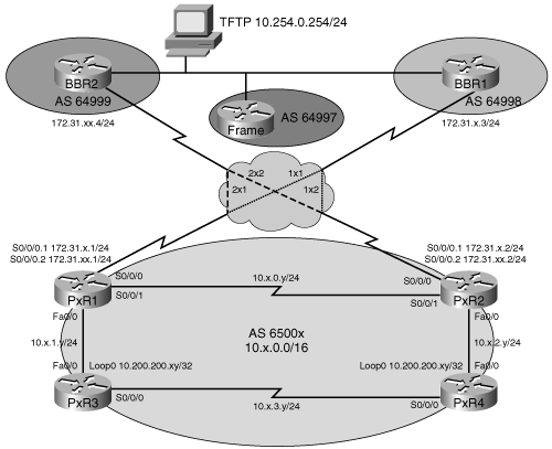
In this exercise, you use the commands in Table 8-11, listed in logical order. Refer to this list if you need configuration command assistance during the exercise.
Caution
Although the command syntax is shown in this table, the addresses shown are typically for the PxR1 and PxR3 routers. Be careful when addressing your routers! Refer to the exercise instructions and the appropriate visual objective diagram for addressing details.
Table 8-11. BGP Path Manipulation Configuration Exercise Commands
Command | Description |
|---|---|
#show ip bgp | Displays the BGP table. |
(config)#route-map SET_PREF permit 10 | Creates a route map named SET_PREF. |
(config-route-map)#match ip address 3 | Used in a route map to match an IP address to routes that are permitted by access list 3. |
(config-route-map)#set local-preference 300 | Used in a route map to set the BGP local preference. |
(config)#access-list 3 permit 172.31.0.0 0.0.255.255 | Creates access list 3. |
(config-router)#neighbor 172.31.xx.4 route-map SET_PREF in | Applies a route map to the incoming updates from a BGP neighbor. |
#clear ip bgp 172.31.xx.4 in | Performs a BGP route refresh that provides a dynamic soft reset of inbound BGP routing table updates. |
(config-route-map)#set metric 200 | Used in a route map to set the BGP MED. |
#clear ip bgp 172.31.11.4 out | Performs a BGP soft reset for outbound updates. |
In this task, you change the MED and local preference to manipulate the BGP path-selection process, as shown in Figure 8-45.

On the edge routers, look at the BGP table, and notice the next hop for routes to the 172.31.x.0 and 172.31.xx.0 networks in the other pod (in other words, the networks that connect the BBR1 and BBR2 routers to the other pod); these networks are referred to as the remote networks in this exercise. For example, if you are using pod 1, look for pod 2 routes.
Solution:
The following shows sample output on the P1R1 router. The highlighted lines show the networks 172.31.2.0 and 172.31.22.0, which are the networks that connect pod 2 to the BBR1 and BBR2 routers.
P1R1#show ip bgp
BGP table version is 17, local router ID is 10.200.200.11
Status codes: s suppressed, d damped, h history, * valid, > best, i - internal,
              r RIB-failure, S Stale
Origin codes: i - IGP, e - EGP, ? - incomplete

   Network          Next Hop            Metric LocPrf Weight Path
* i10.1.0.0/24      10.200.200.12            0    100      0 i
*>                  0.0.0.0                  0         32768 i
* i10.1.1.0/24      10.1.2.4                 2    100      0 i
*>                  0.0.0.0                  0         32768 i
* i10.1.2.0/24      10.200.200.12            0    100      0 i
*>                  10.1.1.3                 2         32768 i
* i10.1.3.0/24      10.1.2.4                 1    100      0 i
*>                  10.1.1.3                 1         32768 i
*> 10.97.97.0/24    172.31.1.3                             0 64998 64997 i
* i                 172.31.1.3               0    100      0 64998 64997 i
*                   172.31.11.4                            0 64999 64997 i
r>i10.200.200.13/32 10.200.200.13            0    100      0 i
r>i10.200.200.14/32 10.200.200.14            0    100      0 i
*> 10.254.0.0/24    172.31.1.3               0             0 64998 i
* i                 172.31.1.3               0    100      0 64998 i
*                   172.31.11.4                            0 64999 64998 i
r> 172.31.1.0/24    172.31.1.3               0             0 64998 i
r i                 172.31.1.3               0    100      0 64998 i
r                   172.31.11.4                            0 64999 64998 i
*> 172.31.2.0/24    172.31.1.3               0             0 64998 i
* i                 172.31.1.3               0    100      0 64998 i
*                   172.31.11.4                            0 64999 64998 i
r  172.31.11.0/24   172.31.1.3                             0 64998 64999 i
r i                 172.31.11.4              0    100      0 64999 i
r>                  172.31.11.4              0             0 64999 i
*  172.31.22.0/24   172.31.1.3                             0 64998 64999 i
* i                 172.31.11.4              0    100      0 64999 i
*>                  172.31.11.4              0             0 64999 i
P1R1#
Which path does the edge router use to reach the remote 172.31.x.0 networks? Why does BGP choose that path?
Which path does the edge router use to reach the remote 172.31.xx.0 networks? Why does BGP choose that path?
Solution:
P1R1 and P1R2 use 172.31.1.3 (BBR1) to reach 172.31.2.0/24 and use 172.31.11.4 (BBR2) to reach 172.31.22.0/24. These are the shortest AS-path external routes to these networks; there is one AS in the selected path.
This company has established a policy that all traffic exiting the AS bound for any of the remote 172.31.x.0 and 172.31.xx.0 networks should take the path through BBR2.
To comply with this policy, configure the edge routers, PxR1 and PxR2, with a route map setting local preference to 300 for any routes to the remote 172.31.x.0 and 172.31.xx.0 networks that are advertised by BBR2.
Solution:
The following shows the required steps on the P1R1 router:
P1R1(config)#route-map SET_PREF permit 10
P1R1(config-route-map)#match ip address 3
P1R1(config-route-map)#set local-preference 300
P1R1(config-route-map)#route-map SET_PREF permit 20
P1R1(config-route-map)#exit
P1R1(config)#access-list 3 permit 172.31.0.0 0.0.255.255
P1R1(config)#router bgp 65001
P1R1(config-router)#neighbor 172.31.11.4 route-map SET_PREF in
Look at the BGP table on the edge routers. Has the local preference for the routes learned from BBR2 changed?
Solution:
The following shows the BGP table on the P1R1 router. The local preference has not changed.
P1R1#show ip bgp
BGP table version is 17, local router ID is 10.200.200.11
Status codes: s suppressed, d damped, h history, * valid, > best, i - internal,
              r RIB-failure, S Stale
Origin codes: i - IGP, e - EGP, ? - incomplete

   Network          Next Hop            Metric LocPrf Weight Path
* i10.1.0.0/24      10.200.200.12            0    100      0 i
*>                  0.0.0.0                  0         32768 i
* i10.1.1.0/24      10.1.2.4                 2    100      0 i
*>                  0.0.0.0                  0         32768 i
* i10.1.2.0/24      10.200.200.12            0    100      0 i
*>                  10.1.1.3                 2         32768 i
* i10.1.3.0/24      10.1.2.4                 1    100      0 i
*>                  10.1.1.3                 1         32768 i
*> 10.97.97.0/24    172.31.1.3                             0 64998 64997 i
* i                 172.31.1.3               0    100      0 64998 64997 i
*                   172.31.11.4                            0 64999 64997 i
r>i10.200.200.13/32 10.200.200.13            0    100      0 i
r>i10.200.200.14/32 10.200.200.14            0    100      0 i
*> 10.254.0.0/24    172.31.1.3               0             0 64998 i
* i                 172.31.1.3               0    100      0 64998 i
*                   172.31.11.4                            0 64999 64998 i
r> 172.31.1.0/24    172.31.1.3               0             0 64998 i
r i                 172.31.1.3               0    100      0 64998 i
r                   172.31.11.4                            0 64999 64998 i
*> 172.31.2.0/24    172.31.1.3               0             0 64998 i
* i                 172.31.1.3               0    100      0 64998 i
*                   172.31.11.4                            0 64999 64998 i
r  172.31.11.0/24   172.31.1.3                             0 64998 64999 i
r i                 172.31.11.4              0    100      0 64999 i
r>                  172.31.11.4              0             0 64999 i
*  172.31.22.0/24   172.31.1.3                             0 64998 64999 i
* i                 172.31.11.4              0    100      0 64999 i
*>                  172.31.11.4              0             0 64999 i
P1R1#
When you configure a policy, it is not automatically applied to routes already in the BGP table. You can perform a hard or soft reset of the BGP relationship with BBR2, or use the route refresh feature that provides a dynamic soft reset of inbound BGP routing table updates. To use the route refresh feature to apply the policy to the routes that have come in from BBR2, use the clear ip bgp 172.31.xx.4 soft in command. (Recall that you do not actually need to use the soft keyword, because soft reset is assumed when the route refresh capability is supported.)
Look at the BGP table again. Have the local preference values changed?
Solution:
The following shows the route refresh on P1R1, and the BGP table on the same P1R1 router. The local preference has now changed.
P1R1#clear ip bgp 172.31.11.4 in
P1R1#show ip bgp
BGP table version is 21, local router ID is 10.200.200.11
Status codes: s suppressed, d damped, h history, * valid, > best, i - internal,
              r RIB-failure, S Stale
Origin codes: i - IGP, e - EGP, ? - incomplete

   Network          Next Hop            Metric LocPrf Weight Path
* i10.1.0.0/24      10.200.200.12            0    100      0 i
*>                  0.0.0.0                  0         32768 i
* i10.1.1.0/24      10.1.2.4                 2    100      0 i
*>                  0.0.0.0                  0         32768 i
* i10.1.2.0/24      10.200.200.12            0    100      0 i
*>                  10.1.1.3                 2         32768 i
* i10.1.3.0/24      10.1.2.4                 1    100      0 i
*>                  10.1.1.3                 1         32768 i
*> 10.97.97.0/24    172.31.1.3                             0 64998 64997 i
* i                 172.31.1.3               0    100      0 64998 64997 i
*                   172.31.11.4                            0 64999 64997 i
r>i10.200.200.13/32 10.200.200.13            0    100      0 i
r>i10.200.200.14/32 10.200.200.14            0    100      0 i
*> 10.254.0.0/24    172.31.1.3               0             0 64998 i
* i                 172.31.1.3               0    100      0 64998 i
*                   172.31.11.4                            0 64999 64998 i
r i172.31.1.0/24    172.31.11.4              0    300      0 64999 64998 i
r                   172.31.1.3               0             0 64998 i
r>                  172.31.11.4                   300      0 64999 64998 i
* i172.31.2.0/24    172.31.11.4              0    300      0 64999 64998 i
*                   172.31.1.3               0             0 64998 i
*>                  172.31.11.4                   300      0 64999 64998 i
r i172.31.11.0/24   172.31.11.4              0    300      0 64999 i
r                   172.31.1.3                             0 64998 64999 i
r>                  172.31.11.4              0    300      0 64999 i
* i172.31.22.0/24   172.31.11.4              0    300      0 64999 i
*                   172.31.1.3                             0 64998 64999 i
*>                  172.31.11.4              0    300      0 64999 i
P1R1#
Which path does the edge router use to reach the remote 172.31.x.0 networks now? Why does BGP choose that path even though the AS-path is longer?
Which path does the edge router use to reach the remote 172.31.xx.0 networks now? Why does BGP choose that path?
Solution:
P1R1 is using 172.31.11.4 (BBR2) to reach the 172.31.2.0 and 172.31.22.0 networks. The path to 172.31.2.0 through BBR2 was chosen because the local preference is higher; local preference is looked at before AS-path length. Of the two routes with the same local preference, the EBGP route is chosen, because EBGP routes are preferred over IBGP routes.
Both of the core routers (BBR1 and BBR2) have multiple ways into each pod. For example, BBR1 could take the direct path through your pod’s PxR1 or PxR2 router, or it could take a path through BBR2 and then to one of the pod’s edge routers.
Telnet to BBR1 and examine the BGP table. Which path does the BBR1 router use to reach your pod’s 10.x.0.0/24 network? Why does BGP choose that path?
Solution:
The following output is from the BBR1 router. BBR1 uses the 172.31.1.2 path (through P1R2) to get to 10.1.0.0/24. Because all the other parameters are equal, the AS-path is considered when choosing the best route. Of the two routes with an AS-path length of 1, this route was chosen. It must therefore be an older route than the route through P1R1. We know this because if the routes were the same age, the lower neighbor router ID would be considered. The BGP router IDs are the routers’ loopback addresses: P1R1 has a router ID of 10.200.200.11, and P1R2 (172.31.1.2) has a router ID of 10.200.200.12; P1R1’s router ID is lower than P1R2’s router ID, and P1R1 would therefore have been chosen if router IDs were considered.
BBR1#show ip bgp
BGP table version is 216, local router ID is 172.31.2.3
Status codes: s suppressed, d damped, h history, * valid, > best, i - internal,
              r RIB-failure, S Stale
Origin codes: i - IGP, e - EGP, ? - incomplete

   Network          Next Hop            Metric LocPrf Weight Path
*  10.1.0.0/24      172.31.1.1               0             0 65001 i
*                   10.254.0.2                             0 64999 65001 i
*>                  172.31.1.2               0             0 65001 i
*> 10.1.1.0/24      172.31.1.1               0             0 65001 i
*                   172.31.1.2               2             0 65001 i
*                   10.254.0.2                             0 64999 65001 i
*  10.1.2.0/24      172.31.1.1               2             0 65001 i
*>                  172.31.1.2               0             0 65001 i
*                   10.254.0.2                             0 64999 65001 i
*  10.1.3.0/24      172.31.1.1               1             0 65001 i
*>                  172.31.1.2               1             0 65001 i
*                   10.254.0.2                             0 64999 65001 i
*  10.97.97.0/24    10.254.0.3                             0 64999 64997 i
*>                  10.254.0.3               0             0 64997 i
*  10.200.200.13/32 172.31.1.1                             0 65001 i
*>                  172.31.1.2                             0 65001 i
*                   10.254.0.2                             0 64999 65001 i
*  10.200.200.14/32 172.31.1.1                             0 65001 i
*                   10.254.0.2                             0 64999 65001 i
*>                  172.31.1.2                             0 65001 i
*> 10.254.0.0/24    0.0.0.0                  0         32768 i
*> 172.31.1.0/24    0.0.0.0                  0         32768 i
*> 172.31.2.0/24    0.0.0.0                  0         32768 i
*  172.31.11.0/24   172.31.1.1                             0 65001 64999 i
*                   172.31.1.2                             0 65001 64999 i
*                   10.254.0.2                             0 64997 64999 i
*>                  10.254.0.2               0             0 64999 i
*  172.31.22.0/24   172.31.1.1                             0 65001 64999 i
*                   172.31.1.2                             0 65001 64999 i
*                   10.254.0.2                             0 64997 64999 i
*>                  10.254.0.2               0             0 64999 i
BBR1#
Telnet to BBR2 and examine the BGP table. Which path does the BBR2 router use to reach your pod’s 10.x.0.0/24 network? Why does BGP choose that path?
Solution:
The following output is from the BBR2 router. BBR2 uses the 172.31.11.2 path (through P1R2) to get to 10.1.0.0/24. Because all the other parameters are equal, the AS-path is considered when choosing the best route. Of the two routes with an AS-path length of 1, this route was chosen. It must therefore be an older route than the route through P1R1, for the same reasons as described in the solution for the previous step.
BBR2#show ip bgp
BGP table version is 220, local router ID is 172.31.22.4
Status codes: s suppressed, d damped, h history, * valid, > best, i - internal,
              r RIB-failure, S Stale
Origin codes: i - IGP, e - EGP, ? - incomplete

   Network          Next Hop            Metric LocPrf Weight Path
*  10.1.0.0/24      172.31.11.1              0             0 65001 i
*>                  172.31.11.2              0             0 65001 i
*                   10.254.0.1                             0 64997 64998 65001 i
*                   10.254.0.1                             0 64998 65001 i
*> 10.1.1.0/24      172.31.11.1              0             0 65001 i
*                   172.31.11.2              2             0 65001 i
*                   10.254.0.1                             0 64997 64998 65001 i
*                   10.254.0.1                             0 64998 65001 i
*  10.1.2.0/24      172.31.11.1              2             0 65001 i
*>                  172.31.11.2              0             0 65001 i
*                   10.254.0.1                             0 64997 64998 65001 i
*                   10.254.0.1                             0 64998 65001 i
*  10.1.3.0/24      172.31.11.1              1             0 65001 i
*>                  172.31.11.2              1             0 65001 i
*                   10.254.0.1                             0 64997 64998 65001 i
*                   10.254.0.1                             0 64998 65001 i
*  10.97.97.0/24    172.31.11.1                            0 65001 64998 64997 i
*                   172.31.11.2                            0 65001 64998 64997 i
*                   10.254.0.3                             0 64998 64997 i
*>                  10.254.0.3               0             0 64997 i
*  10.200.200.13/32 172.31.11.1                            0 65001 i
*>                  172.31.11.2                            0 65001 i
*                   10.254.0.1                             0 64997 64998 65001 i
*                   10.254.0.1                             0 64998 65001 i
*  10.200.200.14/32 172.31.11.1                            0 65001 i
*>                  172.31.11.2                            0 65001 i
*                   10.254.0.1                             0 64997 64998 65001 i
*                   10.254.0.1                             0 64998 65001 i
r  10.254.0.0/24    172.31.11.1                            0 65001 64998 i
r                   172.31.11.2                            0 65001 64998 i
r                   10.254.0.1                             0 64997 64998 i
r>                  10.254.0.1               0             0 64998 i
*  172.31.1.0/24    10.254.0.1                             0 64997 64998 i
*>                  10.254.0.1               0             0 64998 i
*  172.31.2.0/24    10.254.0.1                             0 64997 64998 i
*>                  10.254.0.1               0             0 64998 i
*> 172.31.11.0/24   0.0.0.0                  0         32768 i
*> 172.31.22.0/24   0.0.0.0                  0         32768 i
BBR2#
Suppose this company has also established a policy for traffic inbound from the core. This policy states the following:
Traffic from BBR1 to your pod 10.x.0.0/24 network should enter your pod through PxR1.
Traffic from BBR2 to your pod 10.x.0.0/24 network should enter your pod through PxR2.
To accomplish this policy, you do the following:
Make the paths through PxR1 look unattractive to BBR2.
Make the paths through PxR2 look unattractive to BBR1.
Currently, the MED for both paths is 0 in the BGP table of both BBR1 and BBR2, so BBR1 and BBR2 pick the oldest EBGP path.
On PxR1, configure a route map that sets the MED to 200 for routes to your pod’s internal network (10.x.0.0/24); apply the route map to updates sent to BBR2. (Remember that a lower MED is more attractive to BGP.)
On PxR2, configure a route map that sets the MED to 200 for routes to your pod’s internal network (10.x.0.0/24); apply the route map to updates sent to BBR1.
Solution:
The following shows the required configuration on P1R1 and P1R2:
P1R1(config)#route-map SET_MED_HI permit 10
P1R1(config-route-map)#match ip address 4
P1R1(config-route-map)#set metric 200
P1R1(config-route-map)#route-map SET_MED_HI permit 20
P1R1(config-route-map)#exit
P1R1(config)#access-list 4 permit 10.1.0.0 0.0.255.255
P1R1(config)#router bgp 65001
P1R1(config-router)#neighbor 172.31.11.4 route-map SET_MED_HI out

P1R2(config)#route-map SET_MED_HI permit 10
P1R2(config-route-map)#match ip address 4
P1R2(config-route-map)#set metric 200
P1R2(config-route-map)#route-map SET_MED_HI permit 20
P1R2(config-route-map)#exit
P1R2(config)#access-list 4 permit 10.1.0.0 0.0.255.255
P1R2(config)#router bgp 65001
P1R2(config-router)#neighbor 172.31.1.3 route-map SET_MED_HI out
Perform a soft reconfiguration after you apply the policy to the BGP neighbor (BBR1 or BBR2) by using the clear ip bgp ip-address soft out command. (Recall that you do not actually need to use the soft keyword, because soft reset is assumed.)
Solution:
The following shows the required command applied to the P1R1 and P1R2 routers:
P1R1#clear ip bgp 172.31.11.4 out

P1R2#clear ip bgp 172.31.1.3 out
Telnet to the core routers, and examine the BGP table. Verify that the MED changes have taken effect.
Solution:
The following output from the BBR1 and BBR2 routers shows that the MED changes have taken effect:
BBR1#show ip bgp
BGP table version is 217, local router ID is 172.31.2.3
Status codes: s suppressed, d damped, h history, * valid, > best, i - internal,
              r RIB-failure, S Stale
Origin codes: i - IGP, e - EGP, ? - incomplete

   Network          Next Hop            Metric LocPrf Weight Path
*> 10.1.0.0/24      172.31.1.1               0             0 65001 i
*                   10.254.0.2                             0 64999 65001 i
*                   172.31.1.2             200             0 65001 i
*> 10.1.1.0/24      172.31.1.1               0             0 65001 i
*                   172.31.1.2               2             0 65001 i
*                   10.254.0.2                             0 64999 65001 i
*  10.1.2.0/24      172.31.1.1               2             0 65001 i
*>                  172.31.1.2               0             0 65001 i
*                   10.254.0.2                             0 64999 65001 i
*  10.1.3.0/24      172.31.1.1               1             0 65001 i
*>                  172.31.1.2               1             0 65001 i
*                   10.254.0.2                             0 64999 65001 i
*  10.97.97.0/24    10.254.0.3                             0 64999 64997 i
*>                  10.254.0.3               0             0 64997 i
*  10.200.200.13/32 172.31.1.1                             0 65001 i
*>                  172.31.1.2                             0 65001 i
*                   10.254.0.2                             0 64999 65001 i
*  10.200.200.14/32 172.31.1.1                             0 65001 i
*                   10.254.0.2                             0 64999 65001 i
*>                  172.31.1.2                             0 65001 i
*> 10.254.0.0/24    0.0.0.0                  0         32768 i
*> 172.31.1.0/24    0.0.0.0                  0         32768 i
*> 172.31.2.0/24    0.0.0.0                  0         32768 i
*  172.31.11.0/24   172.31.1.1                             0 65001 64999 i
*                   172.31.1.2                             0 65001 64999 i
*                   10.254.0.2                             0 64997 64999 i
*>                  10.254.0.2               0             0 64999 i
*  172.31.22.0/24   172.31.1.1                             0 65001 64999 i
*                   172.31.1.2                             0 65001 64999 i
*                   10.254.0.2                             0 64997 64999 i
*>                  10.254.0.2               0             0 64999 i
BBR1#
BBR2#show ip bgp
BGP table version is 220, local router ID is 172.31.22.4
Status codes: s suppressed, d damped, h history, * valid, > best, i - internal,
              r RIB-failure, S Stale
Origin codes: i - IGP, e - EGP, ? - incomplete

   Network          Next Hop            Metric LocPrf Weight Path
*  10.1.0.0/24      172.31.11.1            200             0 65001 i
*>                  172.31.11.2              0             0 65001 i
*                   10.254.0.1                             0 64997 64998 65001 i
*                   10.254.0.1                             0 64998 65001 i
*> 10.1.1.0/24      172.31.11.1              0             0 65001 i
*                   172.31.11.2              2             0 65001 i
*                   10.254.0.1                             0 64997 64998 65001 i
*                   10.254.0.1                             0 64998 65001 i
*  10.1.2.0/24      172.31.11.1              2             0 65001 i
*>                  172.31.11.2              0             0 65001 i
*                   10.254.0.1                             0 64997 64998 65001 i
*                   10.254.0.1                             0 64998 65001 i
*  10.1.3.0/24      172.31.11.1              1             0 65001 i
*>                  172.31.11.2              1             0 65001 i
*                   10.254.0.1                             0 64997 64998 65001 i
*                   10.254.0.1                             0 64998 65001 i
*  10.97.97.0/24    172.31.11.1                            0 65001 64998 64997 i
*                   172.31.11.2                            0 65001 64998 64997 i
*                   10.254.0.3                             0 64998 64997 i
*>                  10.254.0.3               0             0 64997 i
*  10.200.200.13/32 172.31.11.1                            0 65001 i
*>                  172.31.11.2                            0 65001 i
*                   10.254.0.1                             0 64997 64998 65001 i
*                   10.254.0.1                             0 64998 65001 i
*  10.200.200.14/32 172.31.11.1                            0 65001 i
*>                  172.31.11.2                            0 65001 i
*                   10.254.0.1                             0 64997 64998 65001 i
*                   10.254.0.1                             0 64998 65001 i
r  10.254.0.0/24    172.31.11.1                            0 65001 64998 i
r                   172.31.11.2                            0 65001 64998 i
r                   10.254.0.1                             0 64997 64998 i
r>                  10.254.0.1               0             0 64998 i
*  172.31.1.0/24    10.254.0.1                             0 64997 64998 i
*>                  10.254.0.1               0             0 64998 i
*  172.31.2.0/24    10.254.0.1                             0 64997 64998 i
*>                  10.254.0.1               0             0 64998 i
*> 172.31.11.0/24   0.0.0.0                  0         32768 i
*> 172.31.22.0/24   0.0.0.0                  0         32768 i
BBR2#
Notice that the path with a MED of 200 is not chosen as the best path. What is the best path from BBR1 to your pod 10.x.0.0 network now?
What is the best path from BBR2 to your pod 10.x.0.0 network now?
Solution:
The best path from BBR1 to 10.1.0.0 is via 172.31.1.1 (P1R1). When selecting the best path in this case, BGP considers the AS-path length. There are two routes with an AS-path length of 1, but with different MED values. The one with the lower MED, via 172.31.1.1, is selected as the best path.
Similarly, the best path from BBR2 to 10.1.0.0 is via 172.31.11.2 (P1R2). The AS-path is considered before the MED, so the two routes with an AS-path length of 1, through 172.31.11.2 and 172.31.11.1, are considered. The latter has a MED of 200, and the former has a default MED of 0. Because a lower MED is preferred, the route through 172.31.11.2 is selected as the best path.
Save your configurations to NVRAM.
Solution:
The following shows the required step on the P1R1 router.
P1R1#copy run start
Destination filename [startup-config]?
Building configuration...
[OK]
Answer the following questions, and then refer to Appendix A, “Answers to Review Questions,” for the answers.