
Rocking with Blocks
First, a little more block theory, and then you can rock right into those blocks. To use a block in a drawing, you need two things: a block definition and one or more block insertions. AutoCAD doesn't always make the distinction between these two things very clear, but you need to understand the difference to avoid terminal confusion about blocks. (Maybe this syndrome should be called blockheadedness?)
A block definition lives in an invisible area of your drawing file called the block table. (It's one of those sets of named symbols that I describe in Chapter 6.) The block table is like a book of graphical recipes for making different kinds of blocks. Each block definition is like a recipe for making one kind of block. When you insert a block, as described in the section “Inserting blocks,” later in this chapter, AutoCAD creates a special object called a block reference. The block reference points to the recipe and tells AutoCAD, “Hey, draw me according to the instructions in this recipe!”
Although a block may look like a collection of objects stored together and given a name, it's really a graphical recipe (the block definition) plus one or more pointers to that recipe (one or more block references). Each time you insert a particular block, you create another pointer to the same recipe.
The advantages of blocks include
- Grouping objects together when they belong together logically: You can draw a screw using lines and arcs and then make a block definition out of all these objects. When you insert the screw block, AutoCAD treats it as a single object for purposes of copying, moving, and so on.
- Saving time and reducing errors: Inserting a block is, of course, much quicker than redrawing the same geometry again. And the less geometry you draw from scratch, the less opportunity there is to make a mistake.
- Efficiency of storage when you reuse the same block repeatedly: If you insert the same screw block 15 times in a drawing, AutoCAD stores the detailed block definition only once. The 15 block references that point to the block definition take up much less disk space than 15 copies of all the lines, polylines, and arcs.
- The ability to edit all instances of a symbol in a drawing simply by modifying a single block definition: If you decide that your design requires a different kind of screw, you simply redefine the screw's block definition. With this new recipe, AutoCAD then replaces all 15 screws automatically. That's a heck of a lot faster than erasing and recopying 15 screws!
- Varying the appearance of block references by using dynamic blocks: If your design requires a different kind of screw, you simply change the view of the screw to the other kind (assuming, of course, you've defined your screw as a dynamic block). Every instance of the screw in the drawing could show a different kind of screw. And that's a heck of a lot more efficient than creating 15 different block definitions! For the lowdown on creating, inserting, and manipulating dynamic blocks, see Chapter 18.

![]() Blocks aren't all that great for drawing elements that might be used in multiple drawings however, especially if several people are working on and sharing parts of drawings with one another. That's because blocks, after they get into multiple drawings, stay in each drawing; a later modification to a block definition in one drawing does not automatically modify all the other drawings that use that block. If you use a block with your company's logo in a number of drawings and then you decide to change the logo, you must make the change within each drawing that uses the block.
Blocks aren't all that great for drawing elements that might be used in multiple drawings however, especially if several people are working on and sharing parts of drawings with one another. That's because blocks, after they get into multiple drawings, stay in each drawing; a later modification to a block definition in one drawing does not automatically modify all the other drawings that use that block. If you use a block with your company's logo in a number of drawings and then you decide to change the logo, you must make the change within each drawing that uses the block.
 If all you need to do is group some objects so that you can more easily select them for copying, moving, and so on, use AutoCAD's Group feature, which I describe a little more fully in Chapter 10. Type GROUP (or the command alias G) and press Enter, or simply click the Group button on the Home tab's Groups panel (new in AutoCAD 2012). Then just select some objects and you're done. When you're editing drawings that contain groups, press Ctrl+Shift+A to toggle “group-ness” on or off. If you've toggled group-ness on, picking any object in a group selects all objects in the group. If you've toggled it off, picking an object selects only that object, even if it happens to be a member of a group. For more information, refer to Chapter 10 or visit the online help index.
Creating block definitions
To create a block definition from objects in the current drawing, use the Block Definition dialog box. (The other way to create a block definition is by inserting another drawing file into your current drawing as a block, which I explain in the next section.) The following steps show you how to create a block definition by using the Block Definition dialog box:
 On the Ribbon's Home tab, click the Create button on the Block panel.
The Block Definition dialog box appears (see Figure 17-1).
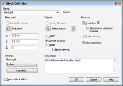
Figure 17-1: The Block Definition dialog box.
Pay attention to layers when you create the objects that make up a block. As a rule, block geometry created on most layers retains the color, linetype, lineweight, transparency, and plot style properties of those layers. The exception to the rule is object geometry created on Layer 0. If you create a block using geometry drawn on Layer 0, then the block takes on the features of any layer into which you insert it.- Type the block definition's name in the Name text box.
If you type the name of an existing block definition, AutoCAD will warn you when you click OK at the end of the process and ask if you want to replace that block definition with the new objects you select. This process is called block redefinition.
To see a list of the names of all the current blocks in your drawing, open the Name drop-down list. - Specify the base point (also known as the insertion point) of the block, using any of the following methods:
- Enter the coordinates of the insertion point in the X, Y, and Z text boxes.
- Click the Pick Point button and then specify a point on the screen. (In this case, use an object snap or other precision technique, as described in Chapter 7, to grab a specific point on one of the block's objects.)
The base point is the point on the block by which you insert it later, as I describe in the next section.
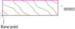
Use an obvious and consistent point on the group of objects for the base point, such as the lower-left corner, so that you know what to expect when you insert the block. - Click the Select Objects button and then select the objects that you want as part of the block.
AutoCAD uses the selected objects to create a block definition and displays an icon showing those objects next to the block name. Figure 17-2 shows the base point and group of selected objects during the process of creating a new block definition.
- In the Objects area, select one of the radio buttons to tell AutoCAD what to do with the objects used to define the block: retain them in place, convert them into a block instance, or delete them.
The default choice, Convert to Block, is usually the best. See Step 9 for a description of what happens with each choice.
- Specify the insert units to which the block will be scaled in the Block Unit drop-down list.
When you or someone else drags the block from one drawing into another via the DesignCenter palette (see Chapter 6) or Tool Palettes (described later in this chapter), the units you specify here and the units of the drawing you're dragging into will control the default insertion scale factor.
Three additional features in AutoCAD's Block Definition dialog box give you even more control over what happens to your blocks as they're inserted:- If the Annotative check box is selected: You can assign multiple plotted drawing scales to the block and then display the inserted block at the different scale representations by choosing one from the Annotation scale list on the status bar. (I explain the nuts and bolts of annotative objects in Chapter 13.)
- If the Scale Uniformly check box is selected: Blocks will be inserted with the same X, Y, or Z scale factors. (Scale Uniformly is selected automatically if Annotative is selected.)
- If the Allow Exploding check box is selected: Blocks can be exploded during or after their insertion in a drawing.
- Enter a description for the block in the Description text area.
You don't have to enter a description to create a block, but it's not a bad idea. Think like a database manager and enter a useful description that will identify the block to yourself and others.
- Make sure that the Open in Block Editor check box is deselected.
You don't need to use the Edit Block Definition dialog box unless you're going to add dynamic features to the block (see Chapter 18 to find out more about dynamic blocks).
- Click OK to complete the block definition process.
AutoCAD stores the block definition in the current drawing's block table. The radio buttons you choose from in Step 5 do the following:
- If you select the Convert to Block radio button (the default) in Step 5, AutoCAD creates a block reference pointing to the new block definition — the objects look the same on-screen, but they are now an instance of the block rather than the original separate objects. Most of the time, this is your best choice.
- If you select the Retain radio button, the objects remain in place but aren't converted into a block reference — they remain individual objects with no connection to the new block definition.
- If you select the Delete radio button, the objects disappear (but the block definition still gets created).
 When you define a block, you can include a special kind of variable text object called an attribute definition. When you insert a block that contains one or more attribute definitions, AutoCAD prompts you to fill in values for the text fields. Attributes are useful for variable title block information (sheet number, sheet title, and so on) and symbols that contain different codes or callouts. I describe how to create and use attribute definitions later in this chapter.
Keep your common symbol drawings in one or more specific folders that you set aside just for that purpose. You may want to use one of the following techniques to develop a library of symbols that you use frequently:
- Create a separate DWG file for each block.
- Store a bunch of symbols as block definitions in one drawing and use DesignCenter to import block definitions from this drawing when you need them.
Inserting blocks
AutoCAD provides a number of ways to insert a block or a whole drawing file, but the most commonly used and most flexible is the Insert dialog box. Here's the procedure for inserting a block:
- Set an appropriate layer current, as described in Chapter 6.
It's a good idea to insert each block on a layer that has something to do with the block's geometry or purpose:
- If all the objects in the block definition reside on one layer, it's usually best to insert the block on that layer.
- If the block geometry spans several layers, choose one of them to insert the block on.
 If any of the block definition's geometry was created on Layer 0, that geometry will inherit the color, linetype, and other object properties of the layer on which you insert the block. It's like the chameleon changing color to match its surroundings or a politician changing his position to match the day's opinion polls.
  On the Ribbon's Home tab click the Insert button on the Block panel.
The Insert dialog box appears, as shown in Figure 17-3.
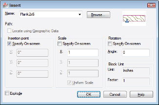
- Enter the block definition name (or external filename) by using one of the following methods:
- Use the Name drop-down list to select from a list of block definitions in the current drawing.
- Click the Browse button to select an external DWG file and have AutoCAD create a block definition from it.
You can use an external drawing to replace a block definition in your current drawing. If you click Browse and choose a file whose name matches the name of a block definition that's already in your drawing, AutoCAD asks you to confirm the update and, if you agree, updates the block definition in your drawing with the current contents of the external file. This process is called block redefinition, and AutoCAD automatically updates all block references that point to the block definition.
- Enter the insertion point, scale, and rotation angle of the block.
You can either select the Specify On-Screen check box in each area to specify the parameters on-screen at the command prompt, or type the values you want in the text boxes in the Insertion Point, Scale, and Rotation areas.
Select the Uniform Scale check box to constrain the X, Y, and Z scaling parameters to the same value (which is what you want in almost all cases). - If you want AutoCAD to create a copy of the individual objects in the block instead of a block reference that points to the block definition, select the Explode check box and click OK.
- If you selected the Specify On-Screen check box for the insertion point, scale, or rotation angle, answer the prompts on the command line to specify these parameters.
After you insert a block, all the objects displayed in the block reference behave as a single object. When you select any object in the block reference, AutoCAD highlights all the objects in it.
Another way to insert a block is to drag a DWG file from Windows Explorer and drop it anywhere in the current drawing window. AutoCAD then prompts you to choose an insertion point and optionally change the default scale factor and rotation angle. Similarly, you can drag a block definition from the Blocks section of the DesignCenter palette and drop it into the current drawing window. (Chapter 6 describes DesignCenter.)
AutoCAD provides one additional way of inserting blocks: the Tool Palettes window, which I describe in Chapter 2. As is true of using a tool palette for hatching (Chapter 15), you first must create and configure appropriate tools. The easiest method is right-clicking a drawing in DesignCenter and choosing Create Tool Palette. A new tabbed page is added to the Tool Palettes window, containing all the block definitions from the drawing that you right-clicked. Simply click and drag a tool to insert its corresponding block into a drawing. Dragging blocks from a tool palette doesn't give you the chance to specify a different insertion scale, nor can you use all AutoCAD's precision tools to specify the insertion point precisely — you may need to move the block into place after inserting it. I recommend that you first master the other block insertion methods described in this chapter — especially the Insert dialog box and DesignCenter palette. Then, if you find yourself inserting the same blocks frequently, consider creating a tool palette containing them. Check out “Add Content with DesignCenter” in the AutoCAD online help system for more information.
Although the preceding paragraph refers to the Tool Palettes window, palettes in AutoCAD are not like regular windows or dialog boxes. They are modeless, which means they can stay open while you carry on with other tasks outside them. The official programmer-ese term for palettes is enhanced secondary window, or ESW for short. (I think I'm sticking with palettes.)
Be careful when you insert one drawing into another. If the host (or parent) drawing and the inserted (or child) drawing have different definitions for layers that share the same name, the objects in the inserted drawing take on the layer characteristics of the host drawing. For example, if you insert a drawing with lines on a layer called Walls that's blue and dashed into a drawing with a layer called Walls that's red and continuous, the inserted lines on the Wall layer will turn red and continuous after they're inserted. The same rules apply to linetypes, text styles, dimension styles, table styles, multileader styles, and block definitions that are nested inside the drawing you're inserting. As you probably remember from when you were little … parents rule!
If you need to modify a block definition after you've inserted one or more instances of it, use the Block Editor (BEDIT command); choose Block Editor on the Home tab's Block panel. Look up BEDIT in the AutoCAD online help system.
Locate Using Geographic Data is an option in AutoCAD's Insert dialog box. Geographic data refers to locating drawing geometry with reference to specific locations on planet Earth (so far) defined in one of a number of recognized global coordinate systems. This feature promises to be very big in the civil engineering community, or possibly for very large architectural projects, where a ground-based coordinate system is in place. If it sounds like something you need, look in the online help (and visit your local dealer or training center for further direction).
Attributes: Fill-in-the-blank blocks
You may think of attributes as the good (or bad) qualities of your significant other, but in AutoCAD, attributes are fill-in-the-blank text fields that you can add to your blocks. When you create a block definition and then insert it several times in a drawing, all the ordinary geometry (lines, circles, regular text strings, and so on) in all the instances are exactly identical. Attributes provide a little more flexibility in the form of text strings that can be different in each block reference.
For example, suppose that you frequently designate parts in your drawings by labeling them with a distinct number or letter in a circle for each part. If you want to create a block for this symbol, you can't simply draw the number or letter as regular text using the MTEXT or TEXT command. If you create a block definition with a regular text object (for example, the letter A), the text string will be the same in every instance of the block (always the letter A). That's not much help in distinguishing the parts!
Instead, you create an attribute definition, which acts as a placeholder for a text string that can vary each time you insert the block. You include the attribute definition when you create the block definition (refer to the “Creating block definitions” section, earlier in this chapter). Then each time you insert the block, AutoCAD prompts you to fill in an attribute value for each attribute definition.
When they were first introduced, and for a long time afterward, block attribute values were limited to a single line of variable text with a maximum of 255 characters. AutoCAD 2008 and later support multiline attributes; as well as offering more than one line, multiline attributes have many of the formatting options of multiline text. For more information on creating and inserting blocks with multiline attributes, look up Define Block Attributes in the online help system.
The AutoCAD documentation and dialog boxes often use the term attribute to refer indiscriminately to an attribute definition or an attribute value. I attribute a lot of the confusion about attributes to this sloppiness. Just remember that an attribute definition is the text field or placeholder in the block definition, and an attribute value is the specific text string that you type when you insert the block.
Creating attribute definitions
You use the Attribute Definition dialog box to create attribute definitions (clever, eh?). The procedure is similar to creating a text string except that you must supply a little more information. Create attribute definitions with the following steps:
- Change to the layer on which you want to create the attribute definition.
- Choose Define Attributes on the Home tab's Block panel slideout to run the ATTDEF command.
The Attribute Definition dialog box appears, as shown in Figure 17-4.
You rarely need to use any of the first four Mode settings (Invisible, Constant, Verify, or Preset). Just leave them deselected. If you're curious about what the modes do, hover your mouse pointer over an item; if that doesn't give you enough information, use the dialog box Help button to find out more. - Select or deselect the Lock Position check box.
If Lock Position is selected, the attributes can't be relocated within the block reference — the whole thing is treated as a single object. Deselecting Lock Position allows attributes to be moved by dragging their grips, without moving the block reference as a whole.
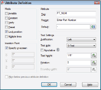
- Select or deselect the Multiple Lines check box.
Selecting Multiple Lines in the Mode area disables the “Default” text box and displays a button to open the Multiline Editor. By default, you don't get the whole panoply of formatting options that you get in the MTEXT command's In-Place Text Editor, but you can overscore or underscore text, and a right-click menu lets you import text, assign a background mask, or choose from a number of other options. Setting the value of the system variable ATTIPE to 1 enables all formatting options in the In-Place Text Editor — refer to the online help system for more information.
- In the Attribute area, type values for the tag (the unique identifier for the attribute), the user prompt, and the default value.
The name you type into the Tag text box can't contain any spaces. The Prompt and Default text boxes may contain spaces.
Attribute values can include fields that automatically update, such as date, filename, or system variable settings. Click the Insert Field button to the right of the Default text box to insert a field. See Chapter 13 for more information on fields.
- (Optional) If you selected the Multiple Lines check box in Step 4, click the Multiline Editor button (it shows three periods) to enter the multiline default attribute value and add any formatting; then click OK.
The value you enter here is the default text stored in the attribute definition, and you can change it when you insert the block.
- In the Text Settings area, specify the Justification, Text Style, Annotative property, Text Height, Rotation, and Boundary Width (the last for multiline attributes only).
The text properties for attribute definitions are the same as those for text objects — see Chapter 13.
- Select Specify On-Screen to choose an insertion point for the attribute definition.
An attribute definition's insertion point is like a text string's base point. Remember to use snap, object snap, or another precision tool if you want the eventual attribute values to be located at a precise point.
- Click OK to create the attribute definition.
- Repeat Steps 1 through 9 for any additional attribute definitions.
If you need to create a series of attribute definitions in neat rows, create the first one using Steps 1 through 9 and then select the Align Below Previous Attribute Definition check box for the subsequent definitions. To make a series of non-adjacent attributes, create the first one using Steps 1 through 9 and then copy the first attribute definition and edit the copy with the Properties palette. You can prevent your attributes from being dragged around the block by selecting the Lock Position check box in the Attribute Definition dialog box.
Defining blocks that contain attribute definitions
After you create one or more attribute definitions — and any other geometry that you want to include in the block — you're ready to create a block definition that contains them. Follow the steps in the section “Creating block definitions,” earlier in this chapter.
At Step 4 in the section “Creating block definitions,” you can select any attribute definitions before or after you select the other geometry. However, you should select each attribute definition one by one (clicking each attribute definition rather than selecting multiple attributes with a selection window) in the order that you want the attribute value prompts to appear in the Edit Attributes dialog box (see Figure 17-5 in the next section). If you don't select the attributes one by one, your block and attributes will still work, but the order of the attribute prompts in the Edit Attributes dialog box may not be what you want.
You can use the Block Attribute Manager to reorder the attribute definitions in a block definition. Choose Attribute, Block Attribute Manager on the Home tab's Block panel slideout. You also can use this dialog box to edit other attribute definition settings, such as the prompt, text style, or layer.
Inserting blocks that contain attribute definitions
After you create a block definition that contains attribute definitions, you insert it just like any other block. Follow the steps in the section “Inserting blocks” earlier in this chapter. At the end of the steps, AutoCAD displays the Edit Attributes dialog box, as shown in Figure 17-5. The dialog box contains one row for each of the attribute definitions and has any default values filled in. You simply edit the values and then click OK.
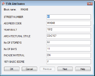
Figure 17-5: The Edit Attributes dialog box.
The ATTDIA (ATTribute DIAlog box) system variable controls whether AutoCAD prompts for attribute values in a dialog box (ATTDIA=1) or at the command line (ATTDIA=0). If you insert a block and see command-line prompts for each attribute value, type a value and press Enter for each attribute value you want to set. When you return to the command prompt, type ATTDIA, press Enter, type 1, and press Enter again. When you insert blocks with attributes into this drawing in the future, AutoCAD displays the Edit Attributes dialog box instead of prompting you at the command line.
Edit attribute values
After you insert a block that contains attributes, you can edit the individual attribute values in that block reference with the EATTEDIT command. Click the Single drop-down button on the Home tab's Block panel and click any object in the block reference. AutoCAD displays the Enhanced Attribute Editor dialog box with the current attribute values, as shown in Figure 17-6. The most common attribute editing operation is to edit the text value—that is, the text string that appears in the block reference. You also can change properties of the attributes, such as layer and text style.
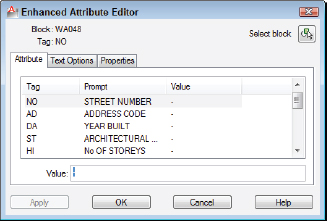
Figure 17-6: The Enhanced Attribute Editor dialog box.
Many people use attributes in the way I've described so far — as fill-in-the-blank text fields in blocks. But attributes also can serve as data extraction tools. For example, you can export attribute values, such as part numbers and quantities, to a table object in AutoCAD or to a text, spreadsheet, or database file for analysis or reporting.
Extracting data
![]() Selecting Extract Data from the Linking & Extraction panel on the Ribbon's Insert tab starts the Data Extraction Wizard. You can find out much more about this specialized function in the online help. Check out User's Guide
Selecting Extract Data from the Linking & Extraction panel on the Ribbon's Insert tab starts the Data Extraction Wizard. You can find out much more about this specialized function in the online help. Check out User's Guide ![]() Share Data between Files
Share Data between Files ![]() Extract Data from Drawings and Spreadsheets. And, AutoCAD LT users, although you don't have this wizard, you can still extract attribute information to space- or comma-delimited text files by using the Attribute Extraction dialog box. For more information, visit the online help.
Extract Data from Drawings and Spreadsheets. And, AutoCAD LT users, although you don't have this wizard, you can still extract attribute information to space- or comma-delimited text files by using the Attribute Extraction dialog box. For more information, visit the online help.
Exploding blocks
In regular block definitions (not dynamic blocks), the objects in each block reference act like a well-honed marching squadron: If you move or otherwise edit one object in the block reference, all objects move or change in the same way. Usually this cohesion is an advantage, but occasionally you need to break up the squadron in order to modify one object without affecting the others.
![]() To explode a block reference into individual objects, click Explode on the Home tab's Modify panel or type X and press Enter, and then select the block reference. When you explode a block reference, AutoCAD replaces it with all the objects — lines, polylines, arcs, and so on — specified in the block definition. You then can edit the objects individually or perhaps use them to make more block definitions.
To explode a block reference into individual objects, click Explode on the Home tab's Modify panel or type X and press Enter, and then select the block reference. When you explode a block reference, AutoCAD replaces it with all the objects — lines, polylines, arcs, and so on — specified in the block definition. You then can edit the objects individually or perhaps use them to make more block definitions.
 If you explode a block that contains attributes, the attribute values change back to attribute definitions. This usually isn't the sort of change that you want. If you really need to explode the block reference, you'll probably want to erase the attribute definitions and draw regular text strings in their place. If you've installed the AutoCAD Express Tools (not available in AutoCAD LT), you can perform this task automatically with the BURST command. Just type BURST and press Enter.
 Both AutoCAD 2012 and AutoCAD LT 2012 have a new NCOPY command that lets you copy objects contained within blocks without having to explode the block. (AutoCAD users familiar with the Express Tools may already be familiar with NCOPY; the command is now in the core of the program and therefore available to LT users for the first time. In both versions, you can find the Copy Nested Objects tool on the Home tab's Modify panel slideout (or you can simply type NCOPY).
Purging unused block definitions
Each block definition slightly increases the size of your DWG file, as do other named objects such as layers, text styles, and dimension styles. If you delete (or explode) all the block references that point to a particular block definition, that block definition no longer serves any purpose.
![]() You should run the PURGE command periodically in each drawing and purge unused block definitions. Click the Application button to open the Application Menu, choose Drawing Utilities on the left side, then choose Purge to display the Purge dialog box. Click the Purge All button to purge all unused named objects in the current drawing.
You should run the PURGE command periodically in each drawing and purge unused block definitions. Click the Application button to open the Application Menu, choose Drawing Utilities on the left side, then choose Purge to display the Purge dialog box. Click the Purge All button to purge all unused named objects in the current drawing.
PURGE isn't only for blocks — you can also remove empty layers, blank text strings, zero-length lines, empty groups (new in AutoCAD 2012), and unused style definitions. In Figure 17-7, the Purge dialog box shows the unused dimension, multileader, and text styles that can be removed from this drawing with a click of the Purge All button.
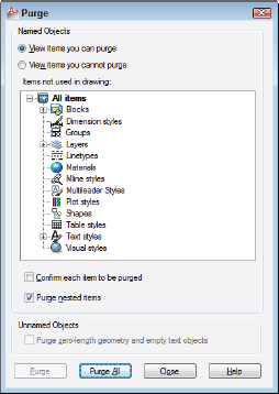
Figure 17-7: Purging your drawing of unneeded named objects.