
Drawing Dimensions
Whew! The hard part is getting it to look right. After you've copied or created a suitable dimension style, you're ready to dimension. Fortunately, adding dimensions to a drawing with existing dimension styles is usually pretty straightforward.
When you want to dimension something in AutoCAD, you can either select the object, such as a line or polyline segment, or select points on that object, such as the endpoints of the line or polyline segment. If you select an object, AutoCAD finds the most obvious points on it to dimension, such as the endpoints of a line. If you choose to select individual points instead, use object snaps (see Chapter 7). When you change the size of the object (for example, by stretching it), AutoCAD automatically moves the dimension's origin points and updates the dimension text to show the new length.
 If you don't use object snaps or another AutoCAD precision technique to choose dimension points, the dimension text probably won't reflect the precise measurement of the object. This lack of precision can cause serious problems. When in doubt, OSNAP to it!
When you set up a new drawing and you want to use annotative dimensions, make sure the Annotative box is selected on the Fit tab in the New/Modify Dimension Style dialog box (refer to Figure 14-7). For a new drawing with non-annotative dimensions, change the Use Overall Scale Of setting on the Fit tab so that it matches the drawing scale factor. Before you draw any dimensions in a drawing that you didn't set up, check this setting to make sure it's correct.
 The AutoCAD dimensioning commands prompt you with useful information at the command line or dynamic-input prompts. Read the prompts during every step of the command, especially when you're trying a dimensioning command for the first time.
Lining up some linear dimensions
 You can find the files I use in this sequence of steps at this book's companion web site. Go to www.dummies.com/go/autocad2012 and download afd14.zip. The drawing named afd14a.dwg contains the mechanical part shown in Figure 14-1.
Linear dimensions are the most common type of dimensions, and horizontal and vertical are the most common of those. The following example demonstrates all the important techniques for creating horizontal and vertical linear dimensions, as well as aligned dimensions (which are similar to linear dimensions):
- Use the LINE command to draw a non-orthogonal line — that is, a line segment that's not horizontal or vertical.
An angle of about 30 degrees works well for this example.
If you want to apply dimensioning to an object other than a line, use these steps as a general guideline, filling in the appropriate commands and data as applicable to your drawing.
- Set a layer that's appropriate for dimensions as current.
Just as with text, it's a good idea to have a dedicated layer for dimensions in every drawing. See Chapter 6 for details on setting a layer as current.
- Set a dimension style that's appropriate for your needs as current.
Choose an existing dimension style from the Dimension Style drop-down list on the Annotation panel slideout on the Ribbon's Home tab, or create a new style by using the procedure in the section “Creating and managing dimension styles,” earlier in this chapter.
 On the Annotate tab's Dimensions panel, click the lower half of the Dimension split button and choose Linear, or type DLI and press Enter.
AutoCAD prompts you:
Specify first extension line origin or <select object>:
- To specify the origin of the first extension line, snap to the lower-left endpoint of the line by using endpoint object snap.
If you don't have endpoint as one of your current running object snaps, specify a single endpoint object snap by holding down the Shift key, right-clicking, and choosing Endpoint from the menu. (See Chapter 7 for more about object snaps.)
AutoCAD prompts you:
Specify second extension line origin:
- To specify the origin of the second extension line, snap to the other endpoint of the line by using endpoint object snap again.
AutoCAD draws a horizontal dimension — the length of the displacement in the left-to-right direction — if you move the crosshairs above or below the line. It draws a vertical dimension — the length of the displacement in the up-and-down direction — if you move the crosshairs to the left or right of the line.
AutoCAD prompts you:
Specify dimension line location or
[Mtext/Text/Angle/Horizontal/Vertical/Rotated]:
- Move the mouse to generate the type of dimension you want, horizontal or vertical, and then click wherever you want to place the dimension line.
AutoCAD draws the dimension.
When you're specifying the dimension line location, you usually don't want to object snap to existing objects — you want the dimension line and text to sit in a relatively empty part of the drawing rather than have it bump into existing objects. If necessary, temporarily turn off running object snap (for example, click the OSNAP button on the status bar) in order to avoid snapping the dimension line to an existing object. If you want to be able to align subsequent dimension lines easily, turn on Snap Mode and set a suitable snap spacing — more easily done than said! — before you pick the point that determines the location of the dimension line. See Chapter 4 for more information about Snap Mode.
  Repeat Steps 4 through 7 to create another linear dimension of the opposite orientation (vertical or horizontal).
- On the Annotate tab's Dimensions panel, click the lower half of the Dimension split button and choose Aligned from the drop-down menu, or type DAL and press Enter.
The prompt includes an option to select an object instead of picking two points (you can use this technique with the Linear Dimension command, too):
Specify first extension line origin or <select object>:
- Press Enter to choose the Select Object option.
AutoCAD prompts you:
Select object to dimension:
- Select the line or other object that you want to dimension.
AutoCAD automatically finds the endpoints of the line and uses them as the extension line's origin points (that is, the defpoints), as shown in Figure 14-8. (The broken extension line is created with the DIMBREAK command, which I describe in the section “More fine tweaking,” later in this chapter.)
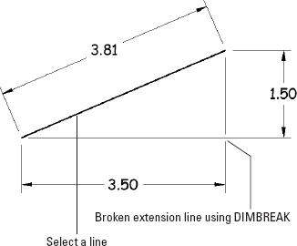
Figure 14-8: Drawing an aligned dimension by selecting an object.
AutoCAD prompts you:
Specify dimension line location or
[Mtext/Text/Angle]:
- Click wherever you want to place the dimension line.
AutoCAD draws the dimension.
Making dimensions annotative
If you've created your dimensions using an annotative style, you can set them up so that they change to the appropriate plotted (paper) size when you change the drawing's annotation scale. The process is the same for dimensions as it is for text (covered in Chapter 13) or for hatching (covered in Chapter 15). Refer to Chapter 13 for details.
Drawing other kinds of dimensions
After you have the hang of ordinary linear dimensions, you should be able to master other common dimension types quickly. Draw some lines, arcs, and circles and try the other dimension commands on the Home tab's Annotation panel or the fuller set on the Annotate tab's Dimensions panel. You'll find more dimension commands on the Dimension toolbar (see “Finding your dimension tools,” earlier in this chapter, for instructions on loading it).
If you want to be super-efficient, learn the three-letter aliases for the dimension commands you use the most.
![]()
To draw a series of side-by-side dimensions whose dimension lines are perfectly aligned, use the DIMCONTINUE command. To draw an overall dimension above one or more smaller dimensions, use DIMBASELINE. To draw a dimension that does not show the actual measured distance that's indicated by the dimension value, use DIMJOGLINE. See Figure 14-9 for examples of these and other dimension types.
The QDIM (Quick DIMension) command provides a quick way to draw lots of dimensions that, when necessary, can format themselves automatically into continued and baseline dimensions in one fell swoop. You can find QDIM on the Annotate tab's Dimensions panel in both AutoCAD and AutoCAD LT.