
Chapter 4. Adding Text and Tables to the Drawing
• Define the terms style and font and describe the function of each.
• Use Dtext (single line text) to draw text.
• Use DDEDIT to change text contents.
• Use different fonts on the same drawing.
• Place text on several different parts of the drawing with a single command.
• Use the modifiers Align, Fit, Center, Middle, Right, Top, and Style.
• Use the Text Style... setting to create condensed, expanded, rotated, backward, inclined, and upside-down text.
• Use the Text Style... setting to change any style on the drawing to a different font.
• Use Properties to change text characteristics.
• Use standard codes to draw special characters such as the degree symbol, the diameter symbol, the plus–minus symbol, and underscored and overscored text.
• Use Mtext (multiline text) to create paragraph text.
• Spell-check your drawing.
• Use the Table command to create door and window schedules.
EXERCISE 4-1 Placing Text on Drawings
To make complete drawings with AutoCAD, you need to know how text is added to the drawings. The following AutoCAD commands, used to place lettering on drawings, are examined in Exercise 4-1.
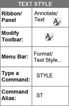
Text Style...: Used to control the appearance of text
Single Line Text (Dtext): Used to draw text that is not in paragraph form
Multiline Text (Mtext): Used to draw text that is in paragraph form
When you have completed Exercise 4-1, your drawing will look similar to the one in Figure 4-1.

Figure 4-1 Exercise 4-1: Placing text on drawings
Tip
If you click New... and select the acad.dwt template, you will be in the same drawing environment as when you simply open the AutoCAD program and begin drawing. AutoCAD uses the acad.dwt template for the drawing settings if no other template is selected.
Step 1. Use your workspace to make the following settings:
1. Use Save As... to save the drawing with the name CH4-EXERCISE1.
2. Set drawing units: Architectural
3. Set drawing limits: 8-1/2,11 (the inch mark is not needed)
4. Set GRIDDISPLAY: 0
5. Set grid: 1/4
6. Set snap: 1/8
7. Create the following layers:

8. Set layer a-anno-text current.
9. Use Zoom-All to view the limits of the drawing.
Making Settings for Text Style
It is important to understand the difference between the terms style name and font name with regard to text:
Style Name
AutoCAD provides in the Text Style dialog box (use ST for Style to see the Text Style dialog box), by default, a style named Standard. By default, the Standard style includes the following settings (Figure 4-2):


Font Name
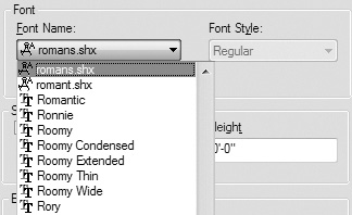
This is the name of any font file. A font determines how text looks by defining its typeface, or graphical design. A font has to be in the AutoCAD program before it can be selected and assigned to a style name. AutoCAD assigns the Arial font to the Standard style by default. AutoCAD has two types of fonts available, as shown in Figure 4-3:
font: A distinctive set of letters, numbers, punctuation marks, and symbols.
![]() TrueType fonts: The standard font type provided by Microsoft Windows. TrueType fonts have the .ttf file name extension. This extension is not shown in the Text Style dialog box Font Name list.
TrueType fonts: The standard font type provided by Microsoft Windows. TrueType fonts have the .ttf file name extension. This extension is not shown in the Text Style dialog box Font Name list.
![]() SHX fonts: AutoCAD’s own set of fonts that have the .shx file name extension. This extension is shown in the Text Style dialog box Font Name list.
SHX fonts: AutoCAD’s own set of fonts that have the .shx file name extension. This extension is shown in the Text Style dialog box Font Name list.
Making a New Text Style
By clicking New... in the Text Style dialog box (Figure 4-2), you can make new text styles.
![]() You can assign any name you choose to the style name. You may use the same name for the style that is used for the font name, or you may use a different name, single number, or letter for the style name.
You can assign any name you choose to the style name. You may use the same name for the style that is used for the font name, or you may use a different name, single number, or letter for the style name.
![]() You can assign the settings to the new text style to include Font Name, Font Style, Annotative, Height, Upside down, Backwards, Vertical, Width Factor, and Oblique Angle.
You can assign the settings to the new text style to include Font Name, Font Style, Annotative, Height, Upside down, Backwards, Vertical, Width Factor, and Oblique Angle.
Step 2. Change the font for the Standard style (Figure 4-4), as described next:
Prompt |
Response |
Type a command: |
Text Style... (or type ST <Enter>) |
The Text Style dialog box appears with the Standard style current: |
Click TechnicLite (in the Font Name: list) Click Apply |

Any text typed while the Standard style is active will now contain the TechnicLite font. Notice the preview area in the lower left corner that shows you what the font looks like. Notice also that the vertical setting is grayed out, indicating that this font cannot be drawn running up and down.
The other settings should be left as they are. If you leave the text height set at 0, you will be able to draw different heights of the same style and you will be able to change the height of text if you need to. Leave the text height set to 0 in all cases. The Width Factor allows you to stretch letters so they are wider by making the Width Factor greater than 1, and narrower by making the Width Factor less than 1. The Oblique Angle slants the letters to the right if the angle is positive and to the left if the angle is negative.
AutoCAD also provides a style named Annotative. This style is used when text is added to a drawing that will be plotted to scale (e.g., 1/4″ = 1′-0″). Any style can be made annotative in the Text Style dialog box by clicking the box under Size and beside Annotative to put a check in the box.
Step 3. Make the settings for a new style that will be used on the drawing (Figures 4-5 and 4-6), as described next:
Prompt |
Response |
The Text Style dialog box: |
Click New... (button on the right) |
The New Text Style dialog box appears with a Style Name that AutoCAD assigns, style1: |
Type HEADING (to name the style, Figure 4-5) Click OK (or press <Enter>) |
The Text Style dialog box appears: |
Click romand.shx (in the Font Name: list, Figure 4-6) Click Apply |

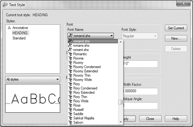
You now have two styles that have been defined on your drawing, Standard and HEADING.
Tip
To locate a font in the Font Name: list, hold your cursor over any font name in the list and type the first few letters of the desired font. You can also scroll through the Font Name: list by pressing the up or down arrow key on the keyboard or by using the wheel on your wheel mouse.
Step 4. Make the settings for the following new styles (Figure 4-7):


Step 5. Check the Styles list to determine whether your list matches the one shown in Figure 4-8.

Step 6. Click the HEADING style name and the Set Current button to make it current; close the dialog box.
Note
If you make a mistake while making the settings for a new style, go back to the Text Style dialog box, highlight the style name, change or fix the settings, and click Apply.
Using the Single Line Text Command to Draw Text
The Single Line Text command (also known as Dtext) is used to draw text that is not in paragraph form. Although the name of the command might lead you to believe that only a single line can be drawn, such is not the case. To draw one line under another, just press <Enter>, and you can draw the next line with the same settings as the first line.

If you are not happy with the location of text, use the MOVE command to relocate it.
Step 7. Draw the first two examples at the top of the page using Single Line Text (Figure 4-9), as described next:
Response |
|
Type a command: |
Single Line Text (or type DT <Enter>) |
Specify start point of text or [Justify Style]: |
Type C <Enter> (to center the text) |
Specify center point of text: |
Type 4-1/4,10 <Enter> (you are locating the center of the line of text using absolute coordinates, 4-1/4″ to the right and 10″ up) |
Specify height <0′-0 3/16″>: |
Type 1/4 <Enter> |
Specify rotation angle of text <0>: |
<Enter> |
The In-Place Text Editor appears on the screen: |
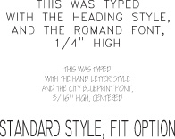
Type THIS WAS TYPED <Enter> Type WITH THE HEADING STYLE, <Enter> Type AND THE ROMAND FONT, <Enter> Type 1/4″ HIGH <Enter> <Enter> (to exit the Text Editor) <Enter> (repeat DTEXT) |
Specify start point of text or [Justify Style]: |
Type S <Enter> (to change styles) |
Enter style name or [?] <HEADING>: |
Type HAND LETTER <Enter> |
Specify start point of text or [Justify Style]: |
Type C <Enter> |
Specify center point of text: |
Type 4-1/4,8 <Enter> |
Specify height <0′-0 3/16″>: |
Type 3/16 <Enter> (or <Enter> to accept a 3/16″ default) |
Specify rotation angle of text <0>: |
<Enter> |
The In-Place Text Editor appears: |
Type THIS WAS TYPED <Enter> Type WITH THE HAND LETTER STYLE <Enter> Type AND THE CITY BLUEPRINT FONT, <Enter> Type 3/16″ HIGH, CENTERED <Enter> <Enter> |

Step 8. Draw the next block of text using the Fit option of Single Line Text with the Standard style (Figure 4-10), as described next:
Prompt |
Response |
Type a command: |
Single Line Text (or type DT <Enter>) |
Specify start point of text or [Justify Style]: |
Type S <Enter> (to change styles) |
Enter style name or [?] <HAND LETTER>: |
Type STANDARD <Enter> |
Specify start point of text or [Justify Style]: |
Type F <Enter> (for Fit) |
Specify first endpoint of text baseline: |
Type 1-1/2,6 <Enter> |
Specify second endpoint of text baseline: |
Type 7,6 <Enter> |
Specify height <0′-0 3/16″>: |
Type 1/2 <Enter> |
The In-Place Text Editor appears: |
Type STANDARD STYLE, FIT OPTION <Enter> <Enter> |
Justify Option
When you activate the Single Line Text command, the prompt is Specify start point of text or [Justify Style]:. The Style option allows you to select a different style (that has already been defined) for the text you are about to draw. If you type J <Enter>, the prompt then becomes Enter an option [Align Fit Center Middle Right TL TC TR ML MC MR BL BC BR]:.
Align: Draws the text between two points that you click. It does not condense or expand the font but instead adjusts the letter height so that the text fits between the two points.
Fit: Draws the text between two clicked points as used in the Align option, but instead of changing the letter height, Fit condenses or expands the font to fit between the points.
Center: Draws the text so that the bottom of the line of lettering is centered on the clicked point. You may also choose the top or the middle of the line of lettering by typing TC or MC at the justify prompt.
Middle: Draws the text so that the middle of the line of lettering is centered around a clicked point. This is useful when a single line of text must be centered in an area such as a box.
Right: Draws the text so that each line of text is right justified (ends at the same right margin). The top or center of the line may also be selected by typing TR or MR at the justify prompt.
TL TC TR ML MC MR BL BC BR: These are the alignment options: Top Left, Top Center, Top Right, Middle Left, Middle Center, Middle Right, Bottom Left, Bottom Center, Bottom Right. They are used with horizontal text.
Step 9. Draw a line of text using the VERTICAL style (Figure 4-11), as described next:
(Remember that you checked Vertical in the Text Style dialog box for this text style.)

Prompt |
Response |
Type a command: |
<Enter> (repeat DTEXT) |
Specify start point of text or [Justify Style]: |
Type S <Enter> |
Enter style name or [?] <Standard>: |
Type VERTICAL <Enter> |
Specify start point of text or [Justify Style]: |
Type 1,6 <Enter> |
Specify height <0′-0″ 3/16″>: |
Type 1/4 <Enter> |
Specify rotation angle of text <0>: |
270 <Enter> |
The In-Place Text Editor appears: |
Type VERTICAL STYLE <Enter> <Enter> |
Using Standard Codes to Draw Special Characters
Figures 4-12 through 4-16 show the use of codes to obtain several commonly used symbols, such as the degree symbol, the diameter symbol, the plus–minus symbol, and underscored and overscored text. The top line of Figure 4-12 shows the code that must be typed to obtain the degree symbol following the number 45. Two percent symbols followed by the letter D produce the degree symbol.

Figure 4-13 illustrates that two percent symbols followed by the letter C produce the diameter symbol.

Figure 4-14 shows the code for the plus–minus symbol.

Figure 4-15 shows the code for underscore: two percent symbols followed by the letter U. Notice that the first line contains only one code. The second line contains two codes: one to start the underline and one to stop it.

Figure 4-16 shows the code for overscored text. The same code sequence applies for starting and stopping the overscore.

Step 10. Draw five lines containing special codes for the overscore, underscore, plus–minus, degree, and diameter symbols (Figure 4-17), as described next:
Prompt |
Response |
Type a command: |
<Enter> (repeat DTEXT) |
Specify start point of text or [Justify Style]: |
Type S <Enter> |
Enter style name or [?] <VERTICAL>: |
Type OVERSCORE <Enter> |
Specify start point of text or [Justify Style]: |
Type 1-1/2,5 <Enter> |

Response |
|
Specify height <0′-0 3/16″>: |
Type 3/16 <Enter> |
Specify rotation angle of text <0>: |
<Enter> |
The In-Place Text Editor appears: |
Type %%OOVERSCORE WITH THE OVERSCORE STYLE <Enter> <Enter> |
Type a command: |
<Enter> (repeat DTEXT) |
Specify start point of text or [Justify Style]: |
Type S <Enter> |
Enter style name or [?] <OVERSCORE>: |
Type STANDARD <Enter> |
Specify start point of text or [Justify Style]: |
Type 1-1/2,4-1/2 <Enter> |
Specify height <0′-0 1/2″>: |
Type 3/16 <Enter> |
Specify rotation angle of text <0>: |
<Enter> |
The In-Place Text Editor appears: |
Type %%OOVERSCORE%%O WITH THE STANDARD STYLE <Enter> <Enter> |
Type a command: |
<Enter> (repeat DTEXT) |
Specify start point of text or [Justify Style]: |
Type 1-1/2,4 <Enter> |
Specify height <0′-0 3/16″>: |
Type 3/16 <Enter> |
Specify rotation angle of text <0>: |
<Enter> |
The In-Place Text Editor appears: |
Type %%UUNDERSCORE WITH THE STANDARD STYLE <Enter> <Enter> |
Type a command: |
<Enter> (repeat DTEXT) |
Specify start point of text or [Justify Style]: |
<Enter> |
The In-Place Text Editor appears: |
Type STANDARD CODES WITH THE STANDARD STYLE <Enter> <Enter> |
Type a command: |
<Enter> (repeat DTEXT) |
Specify start point of text or [Justify Style]: |
Click P1 <Enter> (a point in the approximate location as shown in Figure 4-17) |
Specify height <0′-0 3/16″>: |
<Enter> (to accept the 3/16″ default height) |
Specify rotation angle of text <0>: |
<Enter> |
The In-Place Text Editor appears: |
Type %%P1/16″ <Enter> <Enter> |
Type a command: |
Step 11. Use Single Line Text (DTEXT) to add the following text (3/16 height) to your drawing, as shown in Figure 4-17:
45° (45 %%D)
(Ø1/2″ (%%C1/2″)
Step 12. Make the style name UPSIDE DOWN current.
Tip
When you are typing using the UPSIDE DOWN style, it does not show as upside down and backward on your screen until you have completed typing the text and pressed the <Enter> key twice, once to indicate you do not want a second line of text and once to exit the DTEXT command.
Step 13. Use Single Line Text to draw the following phrase (3/16 height) upside down and backward with its start point at 7,2-1/2 (Figure 4-18):
UPSIDE DOWN AND BACKWARD <Enter>
WITH THE UPSIDEDOWN STYLE, <Enter>
ARIAL FONT <Enter> <Enter>

Using the Multiline Text Command to Draw Text Paragraphs in Columns
The Multiline Text command (also known as Mtext) is used to draw text in paragraph form. The command activates the Text Formatting Editor and the Text Editor tab on the ribbon (Figure 4-19). You can select a defined style, change the text height and case, boldface and italicize some fonts, select a justification style, specify the width of the paragraph (or columns and the space between columns within the paragraph), search for a word and replace it with another, import text, number lines, insert bullets, and select symbols for use on your drawing. In this exercise, you will create a paragraph in two columns using the SansSerif font.

Sans serif is a term that means “without serifs.” Serifs are the small features at the ends of letters and numbers, as shown in Figure 4-20.
sans serif: Any text font that does not contain serifs. Serifs are the small features at the ends of letters and numbers.

Step 14. Create a new text style and use Multiline Text to draw a paragraph in two columns, as described next:
Prompt |
Response |
Type a command: |
Type ST <Enter> |
The Text Style dialog box appears: |
Click New |
The New Text Style dialog box appears: |
Type PARAGRAPH (as the new style name) Click OK |
The Text Style dialog box appears: |
Change the Font Name: to SansSerif Remove checks from Annotative, Upside down, and Backwards (if these are checked) Click Set Current |
The current style has been modified. |
|
Do you want to save your changes? |
Click Yes Click Close |
Type a command: |
Multiline Text... (or type MT <Enter>) |
Specify first corner: |
Type 1-1/2, 2 <Enter> |
Specify opposite corner or [Height Justify Linespacing Rotation Style Width Columns]: |
Type H <Enter> |
Specify height <3/16″>: |
Type 1/8 <Enter> |
Specify opposite corner or [Height Justify Linespacing Rotation Style Width Columns]: |
Type C <Enter> |
Enter column type [Dynamic Static No columns] <Dynamic>: |
Type S <Enter> |
Specify total width: <1′-6″>: |
Type 5-1/2 <Enter> |
Specify number of columns: <2>: |
Type 2 <Enter> |
Specify gutter width: <1″>: |
Type 1/2 <Enter> |
Specify column height: <2″>: |
Type 1 <Enter> |
The Text Formatting Editor appears, and the ribbon changes: |
Click the Justify icon (Figure 4-21) (so the text is flush right and flush left) Type the paragraph shown in Figures 4-21 and 4-23. When you type 1/8 and 1/2 in the paragraph, the dialog box shown in Figure 4-22 appears. Remove the check from Enable Autostacking; click OK After the paragraph is typed correctly, click Close Text Editor (on the ribbon) |


Tip
When the column width and height have been set in the Text Formatting Editor, you do not need to press <Enter> to go to the next line in the paragraph—this happens automatically as you type.
Changing Text Properties
Sometimes you will need to change the text font, height, or content. AutoCAD has several commands that can be used to do this:
Text Style...: Use this command to change the font of a text style that already exists on your drawing.
DDEDIT: (same as double-click): Use this command if you want to change the text contents only for single line text. This command allows you to select multiline text to change its contents and several of its properties.
Properties: Use this command to change any of the text’s characteristics: properties, justification, style, height, rotation angle, the text content, or any of several other properties.
Step 15. Use the Text Style... command to change the font of text typed with the HEADING name from Romand to Impact (Figure 4-24), as described next:
Prompt |
Response |
Type a command: |
Text Style... (or type ST <Enter>) |
The Text Style dialog box appears: |
Click HEADING (in the Styles: list) Click Set Current Click Impact (from the Font Name: list, Figure 4-24) Click Apply Click Close |

Notice that everything you typed with the HEADING style name is now still in the HEADING style but changed to the Impact font.
Step 16. Use the DDEDIT command to change “AND THE ROMAND FONT” at the top of the page to “AND THE IMPACT FONT” (Figure 4-25), as described next:

Prompt |
Response |
Type a command: |
Double-click AND THE ROMAND FONT, |
The In-Place Text Editor appears: |
Click to the right of ROMAND, backspace over ROMAND, and type IMPACT <Enter> (Figure 4-25) |
Select an annotation object or [Undo]: |
<Enter> |

Note
Double-click on any text to edit it. If you double-click and nothing happens, go to Options, Selection tab, Selection modes, and make sure there is a check in the Noun/verb selection box.
Step 17. Double-click on the line of text that reads 1/4″ HIGH and change it to 1/4″ HIGH, CENTERED
Step 18. Use DDEDIT to change the words TWO COLUMNS, 1/8″ HIGH, to the italic font (Figure 4-26), as described next:
Prompt |
Response |
Type a command: |
Double-click any point on the multiline text |
The Text Formatting Editor (Figure 4-26) appears: |
Click the left mouse button to the left of the word TWO, hold it down, and drag it to the end to the word HIGH so that TWO COLUMNS, 1/8″ HIGH, is highlighted, then click I (for italic) on the ribbon Click Close Text Editor (on the ribbon) |

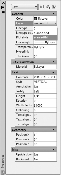
Step 19. Use the Properties palette to change the vertical line of text from layer a-anno-text to layer a-area-ttbl (Figure 4-27), as described next:
Prompt |
Response |
Type a command: |
Click the vertical line of text (VERTICAL STYLE) and right-click |
The right-click menu appears: |
Click Properties |
The Properties palette appears: |
Click Layer Click the down arrow (Figure 4-27) Click a-area-ttbl Click the X in the upper left corner to close VERTICAL STYLE is now changed to a-area-ttbl |


Step 20. Use Single Line Text, Standard style, 1/8″ high to place your name in the upper left corner and class number in the upper right corner. The start point for your name is 1,10-1/2. Use right-justified text for class number (at the Dtext prompt Specify start point of text or [Justify Style]: type R <Enter>. The right endpoint of text baseline is 7-1/2,10-1/2.
Checking the Spelling
AutoCAD has a spell checker that allows you to check the spelling on your drawing. The Spelling command is located on the Annotate panel, or type SP <Enter> at the command prompt to access it.
Step 21. When you have completed Exercise 4-1, save your work in at least two places.
Step 22. Print your drawing from the Model tab at a scale of 1:1.
When you create Mtext in AutoCAD 2015, it automatically applies bullets or numbering, provided these options are enabled in the Text Editor ribbon tab. You can use Manage (from the Menu Bar) and Customize User Interface (CUI) from the Customization panel to add the Text Editor contextual tab to the ribbon. You can use the tcount command to add numbering to existing Mtext objects. For example, the Mtext shown in the left box below becomes that shown in the right box below by using the tcount command and with Starting number = 1, increment = 1, added as prefix:

Tip
When a drawing has a lot of text and annotations, zooming in and out requires auto regeneration of the drawing. This could be time consuming for a very busy drawing. If QTEXT (Quick Text) is turned on, each text and attribute object is displayed as a bounding box around the text object. Turning QTEXT mode on reduces the time it takes to regenerate drawings that contain many text objects. Use the REGEN command to display the results of QTEXT on existing text, with the Visual Style set to 2D Wireframe.
EXERCISE 4-2 Using the TABLE Command to Create a Door Schedule
The TABLE command in AutoCAD 2015 is a tool to create professional-appearing tables such as door schedules, tables for drawing sets, window schedules, and similar items.
When you have completed Exercise 4-2, your drawing will look similar to Figure 4-28. This is a commonly used means of specifying the number and types of doors used in a commercial or residential building.

Step 1. Use your workspace to make the following settings:
1. Use Save As... to save the drawing with the name CH4-EXERCISE2.
2. Set drawing units: Architectural
3. Set drawing limits: 11,8-1/2
4. Set GRIDDISPLAY: 0
5. Set grid: 1/4″
6. Set snap: 1/8″
7. Make a new text style, name it Title, use the Arial Font, and change the Font Style to Bold.
8. Create the following layer:

9. Set layer a-anno-schd current.
10. Use Zoom-All to view the limits of the drawing.
Step 2. Use the TABLE command to modify the Standard table, as described next:

Prompt |
Response |
Type a command: |
Click Table (or type TB <Enter>) |
The Insert Table dialog box, Figure 4-29, appears: |
Click the Launch the Table Style dialog icon (the icon next to the Standard Table style name) |
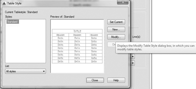
The Table Style dialog box, Figure 4-30, appears: |
At this point you could specify a new table name, but for now just modify the Standard table. Click Modify... |
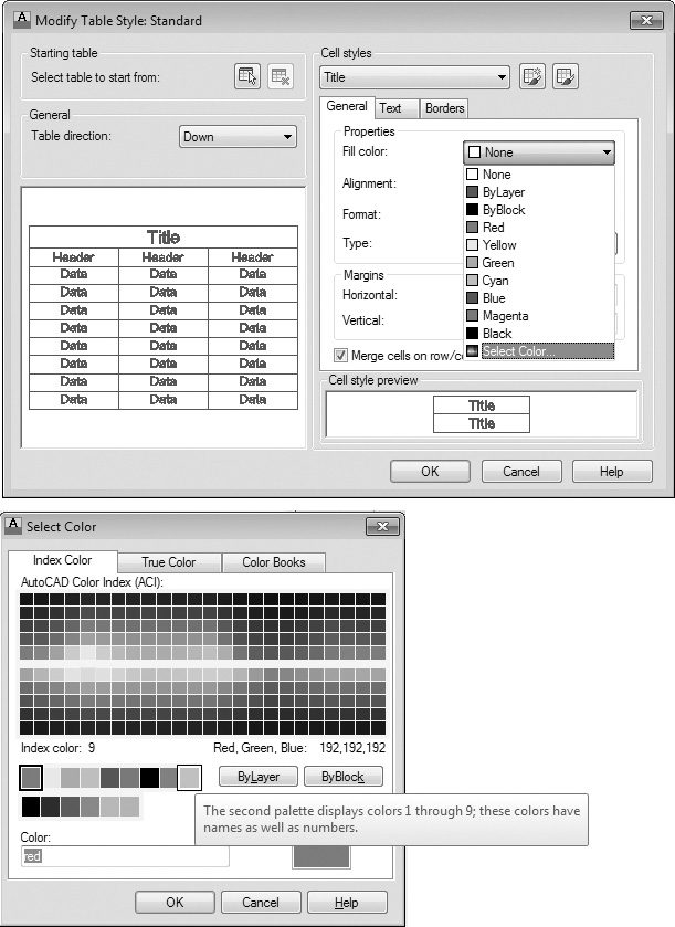
The Modify Table Style: Standard dialog box (Figure 4-31) appears: |
Three cell styles, Title, Header, and Data, are provided within the Standard table. Click Title under Cell styles [Figure 4-31] to make the following settings: |


Prompt |
Response |
Click the General tab (Figure 4-32) Click the Fill color: list down arrow and Select Color... 9 (a light gray as the background color for the Title cell) (You have to click Select Color... at the bottom of the list to access the Index Color tab [Figure 4-32]); click OK |
Prompt |
Response |
Click the Text tab (Figure 4-33) Click the Text style: list down arrow to set the Text style: Title current (Figure 4-33) Click Data under Cell styles (Figure 4-34) to make the following settings: Click the General tab (Figure 4-34) |

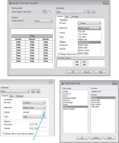
Figure 4-34 Click Data under Cell styles, click Alignment: list arrow and set alignment to Middle Center, click ...button to set Format: to Text
Response |
|
Click the Alignment: list down arrow and set the alignment to Middle Center (Figure 4-34) Click the ... button to set the Format: to Text (Figure 4-34); click OK Click the Text tab (Figure 4-35) Set Text height: to 1/8″ (Figure 4-35) Click OK |
|
The Table Style dialog box appears: |
Click Close |
The Insert Table dialog box appears: |
Make the settings shown in Figure 4-36: 6 columns (you will need only 4, but specify 6 anyway—you will delete 2 of them); set Column width at 2″ (you will change the column widths as you create the table); 5 rows (you will need 7, but specify 5 for now—adding rows is very easy); set Row height: at 1 if it is not the default; click OK |


Step 3. Insert the table and type the title, as described next:
Prompt |
Response |
Specify insertion point: |
Click a point to place the table in the approximate center of the page (It will hang outside the drawing limits for now.) |
The Text Formatting dialog box appears with the cursor flashing in the center of the Title area: |
Type DOOR SCHEDULE <Enter> |
Step 4. Create column 1 head and all data in column 1, as described next:
Prompt |
Response |
The Text Formatting dialog box appears with the cursor flashing in the center of the column 1 header area: |
Type MARK <Enter> |
The Text Formatting dialog box appears with the cursor flashing in the center of the first data area: |
Type 1 <Enter> |
The Text Formatting dialog box appears with the cursor flashing in the center of the second data area: |
Type 2 <Enter> 3 <Enter> through 5 (so the table appears as shown in Figure 4-37. If numbers in the data cells are not in the center, click once on each number, then right-click and click Alignment—Middle Center. You can also select all the data cells at once using a crossing window and align them all at once.) |

Step 5. Insert and delete rows, as described next:
Prompt |
Response |
The table appears as shown in Figure 4-37: |
Click once on the 4 data box, as shown in Figure 4-38 |
The ribbon changes (Figure 4-38): |
Hold down the <Shift> key (so you can select two rows at the same time), and click the next row below, release the <Shift> key, then click Insert Below on the Ribbon Row panel Click the blank box under item 5 and type 6 <Enter>, and 7 <Enter> |

Step 6. Add the remaining column headers (Figure 4-39), as described next:
Prompt |
Response |
Double-click the second column head area |
|
The ribbon changes and the cursor flashes in the center of the column 2 header: |
Type SIZE (do not press <Enter>) Press the <Tab> key |

Prompt |
Response |
The cursor is flashing in the center of the third column header: |
Type QUANTITY Press the <Tab> key |
The cursor is flashing in the center of the fourth column header: |
Type REMARKS Click any point in the screen area |
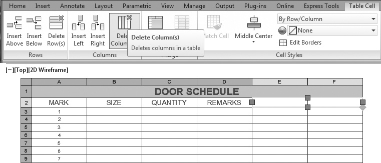
Step 7. Delete unneeded columns (Figure 4-40), as described next:
Prompt |
Response |
Click the two columns to the right of the REMARKS column (hold down the <Shift> key to select the second column) With the two blank columns highlighted, click Delete Column(s) (Figure 4-40) |
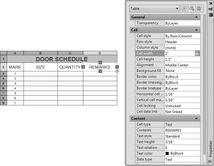
Step 8. Change the width of the columns to fit the data text (Figure 4-41), as described next:
Prompt |
Response |
Click once on the first column header (MARK) and right-click |
|
The right-click menu appears: |
Click Properties |
The Properties palette appears: |
Change Cell width to 1″ and Cell height to 1/2″ (Figure 4-41) |

Step 9. Change the width of the remaining columns (Figure 4-42):
Column 2 (SIZE)—change to 1-1/2″
Column 3 (QUANTITY)—change to 1-1/2″
Column 4 (REMARKS)—change to 2″
Close the Properties palette.
Step 10. Click the first cell under the SIZE column header and type 2′0″ × 6′8″ <Enter>. Type each remaining door size (Figure 4-43) and press <Enter>.

Figure 4-43 Type each door size, quantity, and description; select all data cells in the REMARKS column
Step 11. Double-click the first cell under the QUANTITY column header and type each door quantity (Figure 4-43) and press <Enter>.
Step 12. Double-click the first cell under the REMARKS column header and type each door description (Figure 4-43) and press <Enter>.
Step 13. Align data in the REMARKS column middle left (Figures 4-43, 4-44, and 4-45), as described next:


Prompt |
Response |
With no command active: |
Click P1→ (Figure 4-43) |
Specify opposite corner: |
Click P2→ (to window the data in the REMARKS column) |
The ribbon changes: |
Click Alignment—Middle Left (from the Cell Styles panel, Figure 4-44) |
Step 14. Type your name 1/8″ high in the upper right corner.
Step 15. When you have completed Exercise 4-2, save your work in at least two places.
Step 16. Print your drawing from the Model tab at a scale of 1:1.
EXERCISE 4-3 Using the TABLE Command to Create a Window Schedule
When you have completed Exercise 4-3, your drawing will look similar to Figure 4-46. This is a commonly used means of specifying the number and types of windows used in a commercial or residential building.

Step 1. Use the information described in Exercise 4-2 to complete the window schedule shown in Figure 4-46.
Step 2. You may copy CH4-EXERCISE2, save it as CH4-EXERCISE3, and make changes as needed to make the new table.
Chapter Summary
In this chapter you learned to add text and tables to drawings. In addition, you learned to make window and door schedules and a title block, and to spell-check drawings. Now you have the skills and information necessary to add text to drawings and to make window and door schedules. You also learned to use the SPELLING command to make sure there are no misspelled words in your drawings.
Chapter Test Questions
Multiple Choice
Circle the correct answer.
1. The command used in this chapter to place line text (text not in paragraph form) on drawings is:
a. Single Line Text (Dtext)
b. TXT
c. Multiline Text (Mtext)
d. DDedit
2. The command used in this chapter to place paragraph text on drawings is:
a. Single Line Text (Dtext)
b. TXT
c. Multiline Text (Mtext)
d. DDedit
3. Which of the following could be used as a style name?
a. SIMPLEX
b. TITLE
c. NAMES
d. All these could be used as a style name.
4. Which of the following is a font name?
a. SIMPLEX
b. TITLE
c. NAMES
d. All these are font names.
5. When you set the text style, which of the following text height settings will allow you to draw different heights of the same text style?
a. 1/4
b. 0′-0″
c. 1
d. 100
6. Which of the following Single Line Text options draws text between two clicked points and adjusts the text height so that it fits between the two points?
a. Fit
b. Align
c. Justify
d. Style
7. Which of the following Single Line Text options draws text between two clicked points and condenses or expands the text to fit between the two points but does not change the text height?
a. Fit
b. Align
c. Justify
d. Style
8. The justification letters MR stand for:
a. Middle, Right-justified
b. Margin, Right-justified
c. Midpoint, Left-justified
d. Bottom, Right-justified
9. Which of the following modifiers should be selected if you want the bottom of the line of text to end 1/2″ above and 1/2″ to the left of the lower right corner of the drawing limits?
a. TL
b. BR
c. BL
d. TR
10. Which of the following best describes the text properties that can be modified for the title, header, and data cell styles?
a. Style
b. Height
c. Color and angle
d. All of the above
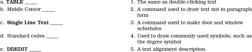
Matching
Write the number of the correct answer on the line.
True or False
Circle the correct answer.
1. True or False: You can change from one text style to another from within the Single Line Text command.
2. True or False: Columns in a table cannot be deleted.
3. True or False: The Properties command allows you to change text height, contents, properties, justification, and style.
4. True or False: The default text style name is Standard, and the default font is Arial.
5. True or False: Paragraph text cannot be used in a drawing.
List
1. Five aliases for text placement and editing available in AutoCAD.
2. Five settings for creating a text style.
3. Five text justifications available in AutoCAD upon launching the text command.
4. Five standard codes for special characters such as the degree (°) and percent (%) symbols.
5. Five Unicode control codes for the following special symbols:
![]()
6. Five options of the Stack Properties dialog box.
7. Five ways of the Check Spelling dialog box.
8. Five options of the New Table Style dialog box.
9. Five options of the Table Cell Format dialog box.
10. Five steps in editing the contents of a cell of a table.
Questions
1. How can tables be modified to contain several lines of headings?
2. When should you use paragraph text?
3. What is Single Line Text used for and what are its options?
4. Name the three cell styles that the standard table style provides.
5. What is the best and most efficient way to modify text?
Chapter Projects
Project 4-1: Lighting Legend [BASIC]
1. Draw the lighting legend as shown in Figure 4-47. Measure Figure 4-47 using a ¼″ = 1′-0″ scale and draw it full size.

Figure 4-47 Project 4-1: Lighting schedule (Scale: ¼″ = 1′-0″)
2. Type your name 6″ high in the upper right corner.
3. Save the drawing in at least two places and print the drawing to Scale: ¼″ = 1′-0″.
Project 4-2: Room Finish Schedule [INTERMEDIATE]
1. Use the TABLE command to draw the room finish schedule as shown in Figure 4-48. Measure Figure 4-48 and draw it full size.

Figure 4-48 Project 4-2: Room finish schedule (Scale: 1″ = 1″)
2. Type your name on the drawing.
3. Save the table in at least two places and print the table at a scale of 1:1, landscape orientation, on an 8-1/2″ × 11″ sheet.
Project 4-3: Door and Frame Schedule [ADVANCED]
1. Use the TABLE command to draw the door and frame schedule as shown in Figure 4-49. Measure Figure 4-49 and draw it full size.

Figure 4-49 Project 4-3: Door and frame schedule (Scale: 1″ = 1″)
2. Type your name on the drawing.
3. Save the table in at least two places and print the table at a scale of 1:1, landscape orientation, on an 8-1/2″ × 11″ sheet.