
Chapter 10. DesignCenter, Autodesk Seek, Dynamic Blocks, and External References
• Correctly use the following commands and settings:
Attach External Reference (XATTACH)
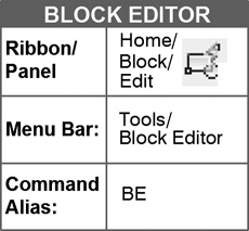
Block Editor (BE)
DesignCenter (DC)
(External Bind) XBIND
External Reference (XREF)
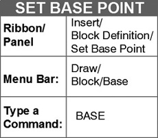
Set Base Point (BASE)
Introduction
In this chapter, you will use the AutoCAD DesignCenter to copy layers and blocks (furniture) from one drawing to another. You will also make blocks that perform actions dynamically. Finally, you will use external reference commands that allow you to attach drawings to other drawings so that they appear in the primary drawing without inserting them.
EXERCISE 10-1 Reception Area Furniture Installation Plan Using the DesignCenter
When you have completed Exercise 10-1, your drawing will look similar to Figure 10-3 without dimensions.
Step 1. Use your workspace to make the following settings:
1. Use Save As... to save the drawing with the name CH10-EXERCISE1.
2. Set drawing units: Architectural
3. Set drawing limits: 44′,34′
4. Set GRIDDISPLAY: 0
5. Set grid: 12″
6. Set snap: 6″
The DesignCenter
The DesignCenter allows you to do the following:
DesignCenter: A dialog box that allows you to use existing blocks that AutoCAD has provided. Drag and drop blocks, layers, linetypes, lineweights, text and dimension styles, and external references from any existing drawing. Search for drawings and other files.
• Use existing blocks arranged in categories that AutoCAD has provided.
• Use blocks, layers, linetypes, text and dimension styles, and external references from any existing drawing using the drag-and-drop technique.
• Examine drawings and blocks as either drawing names or pictures.
• Search for drawings and other files.
Step 2. Open the DesignCenter and examine it, as described next:

Prompt |
Response |
Type a command: |
DesignCenter (or type DC <Enter>) |
The DesignCenter appears: |
Look at the bottom of Figure 10-1. Use the same or similar path to locate the Design Center folder Click Home - Space Planner.dwg |
The DesignCenter shows the blocks and other items in the Home - Space Planner.dwg (Figure 10-1). Your DesignCenter may appear different, depending on what is selected in the Views icon or Tree View Toggle at the top of the DesignCenter. Double-click Blocks |
|
All the predefined blocks for the drawing appear. |

You can now click on any of these drawings, hold down the left mouse button, drag the drawing into the current drawing, and drop it. However, do not do that for this exercise. You will use layers and blocks from CH9-EXERCISE1 to complete CH10-EXERCISE1. Let’s look at the parts of the DesignCenter.
DesignCenter Tabs
The tabs at the top of the DesignCenter allow you to access all the following options of the DesignCenter:
Folders Tab: Clicking this tab shows you the folders existing on the hard drive of your computer.
Open Drawings Tab: Shows you the drawing that is currently open.
History Tab: Shows you a list of the most recently opened drawings.
DesignCenter Buttons
Now, examine the buttons above the tabs. They are listed next, starting from the first one on the left. Click the Folders tab to display all the icons.
Load: Allows you to load drawings and other items that you want to use in your current drawing.
Back: Returns you to the previous screen.
Forward: Sends you forward from a screen obtained from clicking back.
Up: Sends you to the next higher folder structure.
Search: Allows you to search for and locate data you need.
Favorites: Shows what you have in the Favorites folder. You can save your most-often-used items here.
Home: Returns you to the default starting folder.
Tree View Toggle: Displays and hides the tree view. The tree view shows the structure of the files and folders in the form of a chart, the area on the left.
Preview: Allows you to look at a preview of any selected item. If there is no preview image saved with the selected item, the Preview area will be empty.
Description: Shows a text description of any selected item.
Views: Provide you with different display formats for the selected items. You can select a view from the View list or choose the View button again to cycle through display formats.
Large Icons: Shows the names of loaded items with large icons.
Small Icons: Shows the names of loaded items with small icons.
List: Shows a list of loaded items.
Details: Places a name for each item in an alphabetical list.
Autodesk Seek Design Content: Gives you access to thousands of blocks from manufacturers.
Step 3. Use the DesignCenter to load i-furn, a-door, and a-wall-intr layers from CH9-EXERCISE1 into the new drawing, as described next:
Prompt |
Response |
Type a command: |
Click Load Click locate drawing CH9- EXERCISE1 and double-click CH9-EXERCISE1 Double-click Layers (on the left) |
The display (Figure 10-2) appears: |
Click layer a-door, hold down the pick button, drag it into the current drawing (to the right of the DesignCenter), and release the pick button Repeat the previous for layers i-furn and a-wall-intr Close the DesignCenter |

Step 4. Set layer a-wall-intr current.
Step 5. Use Polyline to draw the outside walls of the reception area using the dimensions from Figure 10-3. Set an offset of 5″ for the wall thickness.
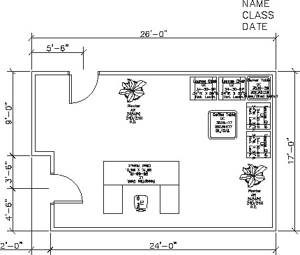
Figure 10-3 Dimensions for Exercise 10-1 (scale: 3/16″ = 1′-0″)
Step 6. Set layer a-door current.
Step 7. Open the DesignCenter and click Blocks under CH9-EXERCISE1, find the block named DOOR, and drag and drop it into the current drawing.
Step 8. Use the MIRROR and ROTATE commands if necessary to correctly position the door.
Step 9. Place doors in the correct locations using the dimensions from Figure 10-3.
Step 10. Use the TRIM command to trim the walls from the door openings.
Step 11. Set layer i-furn current.
Step 12. Click Blocks under CH9-EXERCISE1, find the blocks named Planter, Corner Table, Coffee Table, Reception Desk, Sec Ch, and Lounge Chair, and drag and drop them into the current drawing.
Step 13. Place furniture in the approximate locations shown in Figure 10-3.
Step 14. When you have completed Exercise 10-1, add your name, class, and the current date to the drawing in the upper right and save your work in at least two places.
Step 15. Print Exercise 10-1 to scale.
EXERCISE 10-2 Training Room Furniture Installation Plan Using the DesignCenter, Autodesk Seek, and Dynamic Blocks
When you have completed Exercise 10-2 your drawing will look similar to Figure 10-4.

Figure 10-4 Exercise 10-2: Training room
Step 1. Use your workspace to make the following settings:
1. Open drawing CH3-EXERCISE2 and save it to the hard drive with the name CH10-EXERCISE2.
2. Erase all furniture and the door so that only the walls remain.
3. Set layer a-door current.
DesignCenter
Step 2. Use a block from the DesignCenter - House Designer drawing to draw a new door, as described next:
Prompt |
Response |
Type a command: |
DesignCenter (or type DC <Enter>) |
The DesignCenter appears |
Look at the bottom of Figure 10-5. Use the same or similar path to locate the DesignCenter folder. Click House Designer.dwg |
The available items in the House Designer drawing appear: |
Double-click Blocks and click Large Icons in the Views list, as shown in Figure 10-6. Click Tree View Toggle to remove the tree view. Click on the Door - Right Hung 36 in. icon and continue to hold down the left mouse button (Figure 10-7). Drag the door off the DesignCenter and use Osnap-Endpoint to place it as shown in Figure 10-8. |


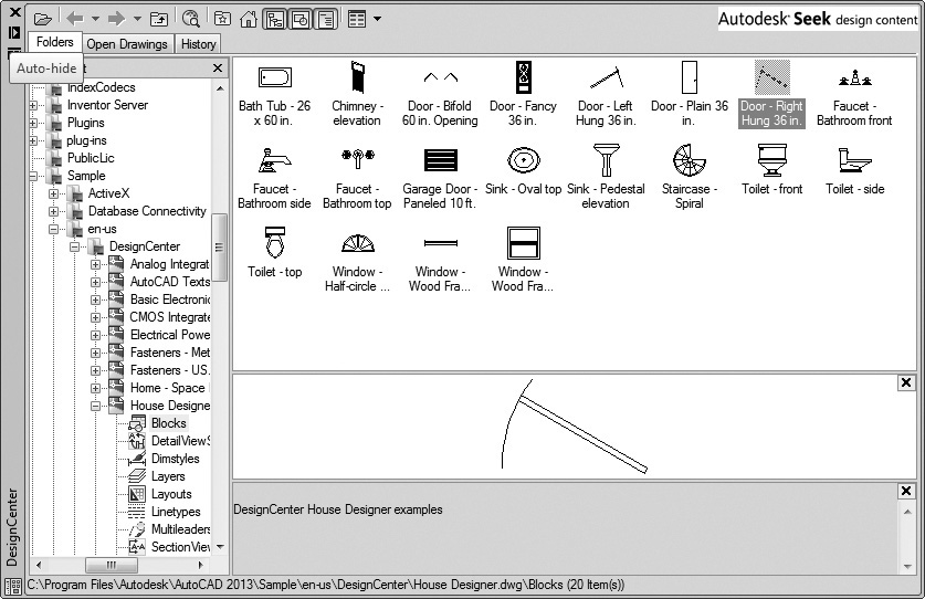
Figure 10-7 Click the Door - Right Hung 36 in. Hold down the pick button and drag the door off the DesignCenter

Step 3. Set the i-furn layer current.
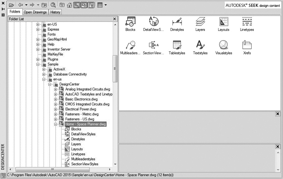
Step 4. Drag and drop blocks from the Home - Space Planner drawing to create furniture in the training room, as described next:
Prompt |
Response |
Type a command: |
Click Tree View Toggle to return to tree view |
The left side of the DesignCenter opens up again: |
Double-click Home - Space Planner .dwg (Figure 10-9) |
Double-click Blocks Click on the Desk - 30 × 60 in. icon and continue to hold down the left mouse button as you drag the Desk off the DesignCenter and place it on the drawing |
Tip
To minimize the DesignCenter, click on the Auto-hide button (the two triangles below the X) in the upper left corner.
Step 5. Drag and drop the following blocks from the Home - Space Planner drawing (Figure 10-10):

1. Computer Terminal
2. Table - Rectangular Woodgrain 60 × 30 in.
Step 6. Move the Computer Terminal on top of the Desk - 30 × 60 in. (Figure 10-11).

Step 7. Explode the Table - Rectangular Woodgrain 60 × 30 in. and erase the woodgrain so you can see the items you are going to place on top of it. Return the exploded table to the i-furn layer.
Step 8. Place the woodgrain table in the drawing. Copy and rotate the desk and computer terminal, so your drawing looks like Figure 10-11.
Autodesk Seek
Step 9. Locate a copier in DesignCenter Autodesk Seek, download it, and insert it on top of the woodgrain table, as described next:
Prompt |
Response |
Type a command: |
Move your mouse back to the DesignCenter palette |
The DesignCenter opens up again: |
Click the Autodesk Seek design content button (Figure 10-12) |
The Autodesk Seek online source for product specifications and design files appears: |
Click AutoCAD (2D) for file type in the Search input area, Figure 10-12. Type copier in the Search input area. Click the Search button. |
The product specification files appear: |
Scroll down to the Library AutoCAD Architecture image area, locate the Copier - Collator, and click the DWG icon. |
The selected Copier - Collator specification appears: |
Check the file check box and with Download Selected to Local click the Download Selected to Local button to save the file in your drive and folder. |

Step 10. Download the Copier - Collator to your drive and folder.
Step 11. Use the INSERT command to insert the Copier - Collator into your drawing.
Step 12. Locate the Copier - Collator on top of the woodgrain table as shown in Figure 10-4.
Use Block Editor to Make Dynamic Blocks
You can move part of an inserted dynamic block within the dynamic block (such as a chair within a chair-and-desk combination) without exploding the block. A dynamic inserted block can be changed without exploding it. A standard inserted block must be exploded before it can be changed. You can also change the size of the dynamic block as you work. For example, if the desk is needed in a variety of sizes, you can define it as a dynamic block that has a parameter (a feature) that allows the width, depth, or both to be changed without exploding the block or redefining it.
dynamic block: The user-defined collection of drawing objects that can be changed without exploding the block.
The Block Editor is used to create dynamic blocks. The Block Editor allows you to add the elements that make a block dynamic. You can create a block from scratch, or you can add dynamic features to an existing block.
In the following part of this exercise you will redefine the existing woodgrain table as a dynamic block that can change size. You will add dynamic blocks of desk chairs that can be visible or invisible. You will also redefine the existing right-hung 36-in. door as a dynamic block that can flip from one side of the wall to the other. Start with the woodgrain table.
Tip
While in the Block Editor you can zoom in and out.
Step 13. Use the Block Editor to add a linear parameter to the woodgrain table (so the length can be easily changed) as described next:
Prompt |
Response |
Type a command: |
Block Editor (or type BE <Enter>) |
The Edit Block Definition dialog box appears: |
Click Table - Rectangular Woodgrain 60 × 30 in. (Figure 10-13) Click OK |
The table appears with woodgrain (you are still in the Block Editor) |
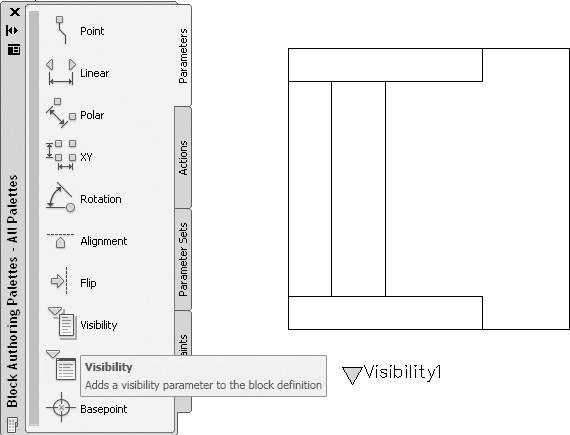
Erase the woodgrain Click the Parameters tab of the Block Authoring Palettes Click Linear |
Specify start point or [Name Label Chain Description Base Palette Value set]: |
Click Osnap-Endpoint, the upper left corner of the table |
Specify endpoint: |
Click Osnap-Endpoint, the upper right corner of the table |

Response |
|
Specify label location: |
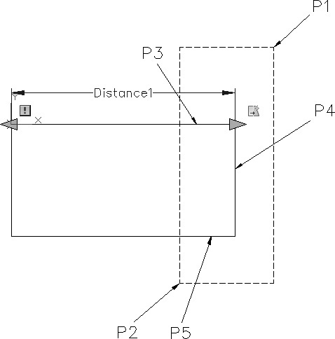
Click to place the label (Distance1) as shown in Figure 10-14 Click the Actions tab of the Block Authoring Palettes Click Stretch |
Select parameter: |
Click Distance1 (on the top of the table). |
Specify parameter point to associate with action or enter [sTart point Second point] <Start>: |
Click the arrow on the upper right corner of the table |
Specify first corner of stretch frame or [CPolygon]: |
Click P1→ (Figure 10-15) |
Specify opposite corner: |
Click P2→ (Figure 10-15) |
Specify objects to stretch: |
Click P3→ |
Select objects: |
Click P4→ |
Select objects: |
Click P5→ |
Select objects: |
<Enter> |

Step 14. Add a lookup parameter and a lookup action that will appear when the block is inserted (so you can just click a number and the block becomes longer or shorter) as described next:
Prompt |
Response |
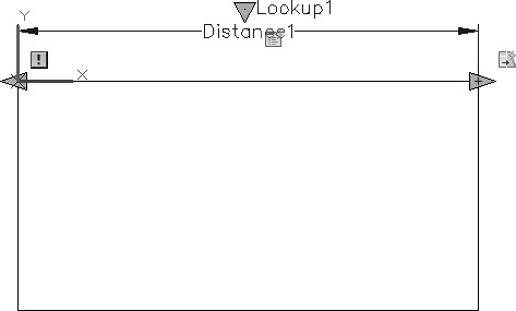
Click the Parameters tab of the Block Authoring Palettes Click Lookup |
|
Specify parameter location or [Name Label Description Palette]: |
Click a point close to the table above it (Figure 10-16) Click the Actions tab of the Block Authoring Palettes Click Lookup |
Select parameter: |
Click the Lookup1 parameter you just made |
The Property Lookup Table appears: |
Click Add Properties... |
The Add Parameter Properties dialog box appears with Linear selected and Add input properties checked |
Click OK |
The Property Lookup Table appears: |
Type the properties shown in Figure 10-17; be sure both columns are identical, then press <Enter> Click Audit (if both columns are identical, you will get the message that no errors were found) Click Close Click OK (to exit the Property Lookup Table) Click Save Block As (or type BSAVEAS <Enter>) |
The Save Block As dialog box appears: |
In the Block Name box, type Table 5′-5′6-6′ Click OK |


Step 15. Close the Block Editor and insert your dynamic block as described next:

Prompt |
Response |
The Block Editor is open. |
Type BC <Enter> or Close Block Editor |
The current drawing appears: |
Erase the copier table (do not erase the copier) |
Type a command: |
Type I <Enter> |
The Insert dialog box appears: |
Select: Table 5′-5′6-6′ Click OK |
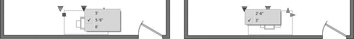
Click a point to replace the copier table you just erased <Enter> Click any point on a line of the inserted table Click the Lookup symbol, Figure 10-18 (to see the three sizes) |

Step 16. You can now click on any of the three numbers, and the block changes length. Change the length to 5′6″.
Step 17. Press the <Esc> key to get rid of the block parameters.
Step 18. Add a linear parameter to make the depth of the copier table dynamic so you have 2′-6″ and 3′ table depths, as described next:
Prompt |
Response |
Type a command: |
Block Editor (or type BE <Enter>) |
The Edit Block Definition dialog box appears: |
Click Table 5′-5′6-6′ Click OK |
The table appears: |
Click the Parameters tab of the Block Authoring Palettes Click Linear |
Specify start point or [Name Label Chain Description Base Palette Value set]: |
Click Osnap-Endpoint, the lower right corner of the table |
Specify endpoint: |
Click Osnap-Endpoint, the upper right corner of the table |
Specify label location: |
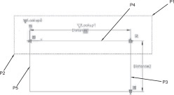
Click to place the label (Distance2) on the right side of the table (Figure 10-19) Click the Actions tab of the Block Authoring Palettes Click Stretch |
Select parameter: |
Click Distance2 (on the right side of the table) |
Specify parameter point to associate with action or enter [sTartpoint Second point] <Start>: |
Click the arrow on the upper right corner of the table |
Specify first corner of stretch frame or [CPolygon]: |
Click P1→ (Figure 10-19) |
Specify opposite corner: |
Click P2→ (Figure 10-19) |
Specify objects to stretch: |
Click P3→ |
Select objects: 1 found |
Click P4→ |
Select objects: 1 found, 2 total |
Click P5→ |
Select objects: 1 found, 3 total |
<Enter> |
Step 19. Add a lookup parameter and a lookup action that will appear when the block is inserted (so you can just click a number, and the block becomes more or less deep), as described next:
Prompt |
Response |
Click the Parameters tab of the Block Authoring Palettes Click Lookup |
|
Specify parameter location or [Name Label Description Palette]: |
Click a point above and to the left of the table (Figure 10-19) Click the Actions tab of the Block Authoring Palettes Click Lookup |
Select parameter: |
Click the Lookup2 parameter you just made |
The Property Lookup Table appears: |
Click Add Properties... |
The Add Parameter Properties dialog box appears with Linear selected and Add input properties checked Click Linear1 Click OK |
|
The Property Lookup Table appears: |
Type the properties shown in Figure 10-20; be sure both columns are identical and click <Enter> Click Audit (if both columns are identical, you will get the message that no errors were found) Click Close Click OK (to exit the Property Lookup Table) Click Save Block As (or type BSAVEAS <Enter>) |
Click Table 5′-5′6-6′ (so it appears in the Block Name area) Click OK |
|
The AutoCAD warning appears: |
|
Block name: is already defined as a block. |
|
What do you want to do? |
Click Redefine block |
The AutoCAD warning appears: |
|
Block—Save parameter changes? |
Click Save the changes |

Step 20. On your own, close the Block Editor, erase the previous Table 5′-5′6-6′ block, and insert the new dynamic block.
Step 21. Click any point on the inserted copier table and click the Lookup symbol showing depth.
Step 22. You can now click on any of the two numbers, and the block changes depth. Change the length to 5′6″ and the depth to 3′. The table is now 5′6″ × 3′ (Figure 10-21).
Step 23. Press the <Esc> key to get rid of the block parameters.
Step 24. Make the Sec Ch and Desk Ch blocks dynamic so you can make one or the other invisible by clicking on it, as described next:
1. Open the DesignCenter (type DC <Enter>). Use the Folders tab to open your drawing CH9-EXERCISE1.
2. Locate the two blocks Sec Ch and Desk Ch and insert both of them into the current drawing, CH10-EXERCISE2.
3. Explode both drawings and erase the attribute tags.
4. Rotate the chairs so they both face the same direction (Figure 10-22).

5. Make a block of the Desk Ch drawing with the name chair1.
6. Make a block of the Sec Ch drawing with the name chair2.
7. Open the Block Editor, select chair1 (Figure 10-23), and click OK.

8. Click the Parameters tab of the Block Authoring Palettes, click the Visibility parameter, and place the parameter below the chair (Figure 10-24). (Below the chair will make it easy to find after the block is inserted again.)
9. Click Visibility States on the Visibility panel on the ribbon.
10. Click New (Figure 10-25) and click Hide all existing objects in new state. Click OK (to exit the New Visibility State dialog box).

11. Click OK (to exit the Visibility States dialog box—you are still in the Block Editor).
12. Click Save Block As and save and redefine the dynamic block as chair1. Close the Block Editor.
13. Erase the existing chair1 block if not deleted.
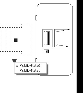
14. Insert chair1 in the approximate location shown in front of a desk (Figure 10-26). Click on chair1 and test your Visibility parameter, VisibilityState0, and VisibilityState1. Chair1 should be visible for State0 and invisible for State1.
15. Repeat items 7 through 13 for chair2.
16. Insert chair2 so it is positioned as shown in Figure 10-27.

17. Copy chair1 and chair2 so each desk has the two chairs.
18. Select all chair1s and use the Properties command to change the Visibility State to 1 (invisible) as shown in Figure 10-28.

19. Make all chair2s visible as shown in Figure 10-28.
Note
To make an invisible block visible again, open the Block Editor and erase the existing visibility parameter on the block. You can then save and redefine the block with no parameter or you can add a new visibility parameter and save and redefine the block.
Step 25. Make the door a dynamic block so it will open in or out, as described next:
1. Open the Block Editor, select Door - Right Hung 36 in., and click OK.
2. Draw a line from P1→ (Figure 10-29) 2-1/2″ straight down. (This line goes to the middle of the wall, so the flip action will flip the door to either side of the room.)
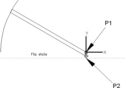
3. Click the Parameters tab of the Block Authoring Palettes; click the Flip parameter.
4. Click P2→ (Figure 10-29, the lower end of the 2-1/2″ line) as the base point of the reflection line. With ORTHO on, click any point to the left of the base point as the endpoint of the reflection line.
5. Locate the label (Figure 10-29).
6. Click the Actions tab of the Block Authoring Palettes, click Flip action, click the Flip state parameter, and then select the entire door and press <Enter>.
7. Save the dynamic block as Door - Right Hung 36 in. to redefine the block and close the Block Editor.
8. Click any point on the door so the flip action is available, flip the door so you see that it works, then leave it as shown in Figure 10-28.
Step 26. When you have completed Exercise 10-2, add your name, class, and current date to the drawing in the upper right and save your work in at least two places.
Step 27. Print Exercise 10-2 to scale.
EXERCISE 10-3 Attach an External Reference to an Office Plan
XATTACH (Attach External Reference)
Before you start the XATTACH command, your primary drawing must be open. When you activate the XATTACH command, the Select Reference File dialog box opens and allows you to select the drawing that you want to attach. When you select and open a drawing to be attached as an external reference to your primary drawing, the External Reference dialog box opens. The External Reference dialog box allows you to specify whether the xref will be an attachment or an overlay.
external reference (xref): A drawing file that is inserted into another drawing. External references have the advantage that the primary drawing always contains the most recent version of the external reference.
Attachment: An attached xref that is then attached to another drawing becomes a nested xref with all its features fully recognized.
Overlay: An overlay is ignored when the drawing on which it is overlaid is then attached as an xref to another drawing.
The XATTACH command allows you to attach an external reference (xref) (drawing) to a primary drawing. For each drawing, the data are stored in their own separate file. Any changes made to the external reference drawing are reflected in the primary drawing each time the primary drawing is loaded into the Drawing Editor.
There are three distinct advantages to using external references:
![]() The primary drawing always contains the most recent version of the external reference.
The primary drawing always contains the most recent version of the external reference.
![]() There are no conflicts in layer names and other similar features (called named objects), such as linetypes, text styles, and block definitions. AutoCAD automatically inserts the drawing name of the xref and a slash (/) in front of the external reference layer name or other object name. For example, if the primary drawing and the external reference (named CHAIR) have a layer named Symbol, then the current drawing layer retains the name Symbol, and the external reference layer in the current drawing becomes CHAIR/symbol.
There are no conflicts in layer names and other similar features (called named objects), such as linetypes, text styles, and block definitions. AutoCAD automatically inserts the drawing name of the xref and a slash (/) in front of the external reference layer name or other object name. For example, if the primary drawing and the external reference (named CHAIR) have a layer named Symbol, then the current drawing layer retains the name Symbol, and the external reference layer in the current drawing becomes CHAIR/symbol.
![]() Drawing files are often much smaller.
Drawing files are often much smaller.
External references are used, for example, for drawing a large furniture plan containing several different levels of office types, such as assistant, associate, manager, vice president, and president. Each office typical (furniture configuration used in the office) is attached to the current drawing as an external reference. When changes are made to the external reference drawing of the manager’s office (as a result of furniture substitution, for example), the change is reflected in each instance of a manager’s office in the primary large furniture plan when it is loaded into the Drawing Editor.
External Reference (XREF)
When you activate the XREF command, the External Reference palette appears. After an external reference has been attached to your drawing, you can right-click on the external reference drawing name to select from the following options:

Attach...: Allows you to attach any drawing as an external reference to the current drawing. There is no limit to the number of external references that you can attach to your drawing. This is the same command as XATTACH.
Detach: Lets you remove unneeded external references from your drawing.
Reload: Allows you to update the current drawing with an external reference that has been changed since you began the current drawing. You do not have to exit the current drawing to update it with an external reference that you or someone else changed while in the current drawing.
Unload: Temporarily clears the external reference from the current drawing until the drawing is reloaded.
Bind...: The Insert option in the Bind dialog box creates a block of the external reference in the current drawing and erases any reference to it as an external reference. The Bind option binds the selected xref to the drawing and renames layers in a manner similar to that of the attached xref. This is the same command as XBIND.
XBIND
The XBIND (External Bind) command allows you to bind a selected subset of an external reference’s dependent symbols to the current drawing. For example, if you did not want to create a block of the entire external reference but wanted permanently to add only a dimension style of the external reference to the drawing, you could use XBIND.

Features of External References
Following is a list of external reference features:
![]() An external reference cannot be exploded.
An external reference cannot be exploded.
![]() An external reference can be changed into a block with the Bind... option and then exploded. The advantage of using the external reference is then lost. The Bind option would be used if you wanted to send a client a disk or file containing only the current drawing without including external references.
An external reference can be changed into a block with the Bind... option and then exploded. The advantage of using the external reference is then lost. The Bind option would be used if you wanted to send a client a disk or file containing only the current drawing without including external references.
![]() External references can be nested. That means that a current drawing containing external references can itself be used as an external reference on another current drawing. There is no limit to the number of drawings you can nest like this.
External references can be nested. That means that a current drawing containing external references can itself be used as an external reference on another current drawing. There is no limit to the number of drawings you can nest like this.
![]() An xref icon appears in the lower right corner of the screen when xrefs are attached to a drawing.
An xref icon appears in the lower right corner of the screen when xrefs are attached to a drawing.
Step 1. Draw the floor plan shown in Figure 10-30 and save it as CH10-EXERCISE3.
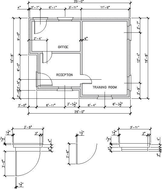
Figure 10-30 Exercise 10-3: Floor plan dimensions (scale: 3/16″ = 1′-0″). Door and window detail dimensions (scale: 3/8″ = 1′-0″)
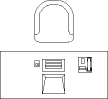
Step 2. Start a new drawing and draw the typical workstation shown in Figure 10-31. Estimate any dimension not shown.

Figure 10-31 Exercise 10-3: Typical workstation dimensions
Step 3. Use the Set Base Point command (or type BASE) to select the midpoint on the arc of the chair as the insertion point for the workstation.
Step 4. Save the typical workstation drawing as WS10-1 in the same folder with CH10-EXERCISE3. Exit the drawing.
Step 5. Open the floor plan drawing CH10-EXERCISE3.
Step 6. Attach the workstation to the floor plan drawing, as described next:
Prompt |
Response |
Type a command: |
XATTACH |
The Select Reference File dialog box (Figure 10-32) appears: |
Locate drawing WS10-1 and click on it Click Open |
The Attach External Reference dialog box (Figure 10-33) appears: |
Click OK |
Specify insertion point or [Scale X Y Z Rotate PScale PX PY PZ PRotate]: |
Click P1→ (Figure 10-34) |
That’s all there is to attaching an external reference to another drawing. |


Step 7. Copy the external reference to four other locations on the floor plan as shown in Figure 10-35 (the exact location is not important).

Step 8. Save your drawing (CH10-EXERCISE3) to the same folder or disk as WS10-1. Exit the drawing.
You have been informed that all the workstations must now have a computer.
Step 9. Open drawing WS10-1 and draw a computer approximately the size shown in Figure 10-36 and label it. Save the new workstation drawing in the same place from which it came.

Step 10. Open drawing CH10-EXERCISE3. It should appear as shown in Figure 10-37.

Step 11. Add your name, class, and current date to the drawing in the upper right and save CH10-EXERCISE3 in the same folder or disk from which it came.
Step 12. Print the drawing to scale.
Chapter Summary
This chapter described the AutoCAD DesignCenter, Autodesk Seek, dynamic blocks, and external references. It showed you how to use the DesignCenter to take blocks, layers, linetypes, and text and dimension styles from any existing drawing using drag and drop and place them in the current drawing. It also showed you how to make external references and dynamic blocks. You will now be able to use these commands to make drawings quickly and efficiently.
Chapter Test Questions
Multiple Choice
Circle the correct answer.
1. The History tab on the DesignCenter allows you to do which of the following?
a. Look at a preview of a selected item
b. Return to the previous screen
c. Display a list of the most recently opened drawings
d. Search for data using the Search command
2. Which of the following opens the Block Editor?
a. BOPEN
b. BE
c. BLOCKE
d. BED
3. Which of the following closes the Block Editor?
a. BCL
b. CLOSE
c. BC
d. EDCL
4. Which of the following External Reference options allows you to make a block of an external reference in the current drawing?
a. Reload
b. Bind
c. Attach...
d. Detach
5. How many external references can be nested on a primary drawing?
a. 1
b. 16
c. 32
d. Unlimited
Matching
Write the number of the correct answer on the line.

True or False
1. True or False: The DesignCenter allows you to drag and drop blocks, layers, linetypes, and text and dimension styles from an existing drawing into the current drawing.
2. True or False: You cannot add dynamic features to an existing block.
3. True or False: Dynamic block parameters and actions can be added to a block using the Block Editor.
4. True or False: Unneeded external references cannot be removed from a drawing.
5. True or False: Only two visibility options are available in the New Visibility State dialog box.
List
1. Five ways of accessing the DesignCenter.
2. Five buttons above the tabs in the DesignCenter.
3. Five types of items available from the DesignCenter/Home Designer list.
4. Five ways of accessing AutoDesk Seek.
5. Five options from Block Authoring Palettes/Adding a lookup parameter.
6. Five ways of accessing the XREF command.
7. Five ways of accessing Attach Ext Ref.
8. Five XREF command options that do not make a block of the XREF in your current drawing.
9. Five features of XREFs.
10. Five block-related commands.
Questions
1. What is the DesignCenter used for?
2. How can dynamic blocks be used effectively?
3. What are the uses of parameters and their actions?
4. How can external references be used to keep the same office configurations consistent?
5. How can you locate items in Autodesk Seek that you need for your drawings?
Chapter Projects
Project 10-1: Dynamic Block (Table and Chair) with Stretch and Move Actions [BASIC]
1. Draw the table with the phone and the computer as shown in Figure 10-38. The phone and the computer terminal are found in the DesignCenter in the Home - Space Planner drawing. The table measures 6′ × 2′-8″.
2. Copy the chair from one of the drawings you completed in Chapter 3.
Place the chair at the midpoint of the table in the X direction and 6″ up.
3. Block the entire drawing with the name table with chair.
4. Access the Block Editor (type BE <Enter>) and add a linear parameter and a lookup parameter to the table.
5. Add a stretch action and a lookup action to the table as shown in Figure 10-39, similar to those in Exercise 10-2. The lengths of the table should be 8′ and 10′.

6. Add a point parameter and a lookup parameter to the chair.
7. Add a move action and a lookup action to the chair as shown in Figure 10-40. The chair should move 1′ and 2′.

8. Save the block and exit the Block Editor.
9. Insert the table with chair block and test it. Move the chair 1′ using the lookup action when you stretch the table to 8′ with its lookup action. Move the chair 2′ when you stretch the table 10′.
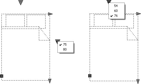
Project 10-2: Dynamic Block (Bed) [BASIC]
1. Insert the Bed-queen as shown in Figure 10-41 and explode it. (You will find it in the DesignCenter in the Home - Space Planner drawing.)

2. Block the entire drawing with the name bed.
3. Access the Block Editor (type BE <Enter>) and add two linear parameters and two lookup parameters to the bed.
4. Add two stretch actions and two lookup actions to the bed as shown in Figure 10-42 similar to those in Exercise 10-2. The lengths of the bed should be 75″ and 80″. The widths of the bed should be 54″, 60″, and 76″.
5. Save the block and exit the Block Editor.
6. Insert the bed block and test it. You should have a dynamic block that gives you three standard bed sizes:
Full size is 54″ × 75″
Queen size is 60″ × 80″
King size is 76″ × 80″
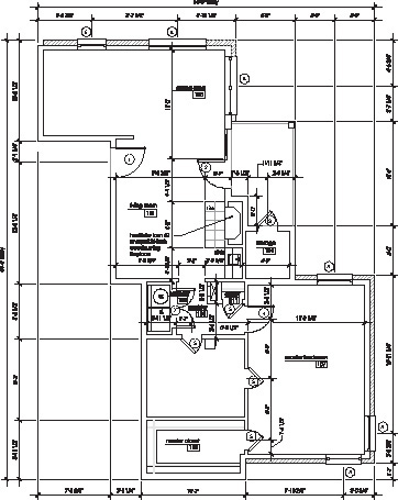
Project 10-3: Condo Floor Plan with External References [ADVANCED]
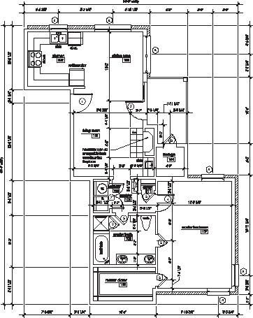
1. Draw full size the floor plan of the condo as shown in Figure 10-43. Use an 1/8″ architect’s scale to measure any features that do not have dimensions. The scale is 1/8″ = 1′-0″.
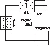
2. Draw full size the original xref kitchen as shown in Figure 10-44. The scale of this figure is 1/4″ = 1′-0″.
3. Attach the original xref kitchen to the condo floor plan as shown in Figure 10-45 and close the condo drawing.
4. Make changes to the original xref kitchen as shown in Figure 10-46. The scale of this figure is 1/4″ = 1′-0″. You will find the new sink, stove, and refrigerator in the Kitchen drawing in the DesignCenter.

5. Draw full size the original xref bathroom as shown in Figure 10-47. The scale of this figure is 1/4″ = 1′-0″.

6. Attach the original xref bathroom to the condo floor plan as shown in Figure 10-45 and close the condo drawing.
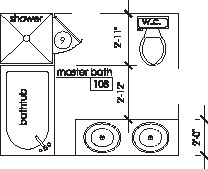
7. Make changes to the original xref bathroom as shown in Figure 10-48. The scale of this figure is 1/4″ = 1′-0″. You will find the new toilet, tub, and sinks in the House Designer drawing in the DesignCenter.
8. Open the condo floor plan. Your drawing should appear as shown in Figure 10-49. You may need to reload the xrefs.

9. Save the drawing in at least two places and print the drawing to scale.
Project 10-4: Log Cabin Floor Plan with External References [INTERMEDIATE]
1. Draw full size the floor plan of the log cabin (or use the one you drew previously) as shown in Figure 10-50. Use a 3/16″ architect’s scale to measure any features that do not have dimensions. The scale is 3/16″ = 1′-0″.

2. Draw full size the original xref bedroom 1 as shown in Figure 10-51. The scale of this figure is 1/4″ = 1′-0″. You will find the bed and lamps in the Home - Space Planner drawing in the DesignCenter. Measure and draw the rectangle as shown.

3. Attach the original xref bedroom 1 to the log cabin floor plan as shown in Figure 10-52 and close the log cabin drawing.

4. Make changes to the original xref bedroom 1 as shown in Figure 10-53. The scale of this figure is 1/4″ = 1′-0″. You will find the entertainment center in the Home - Space Planner drawing in the DesignCenter.

5. Draw full size the original xref bedroom 2 as shown in Figure 10-54. The scale of this figure is 1/4″ = 1′-0″. Use a 1/4″ architect’s scale to measure and draw the rectangle on the west wall.

6. Attach the original xref bedroom 2 to the log cabin floor plan (Figure 10-52) and close the log cabin drawing.
7. Make changes to the original xref bedroom 2 as shown in Figure 10-55. The scale of this figure is 1/4″ = 1′-0″. Use a 1/4″ architect’s scale to measure and draw the rectangle on the west wall.

8. Draw full size the original xref living room as shown in Figure 10-56. The scale of this figure is 1/4″ = 1′-0″. Use a 1/4″ architect’s scale to measure and draw the rectangle and the dining room set. You will find the sofas in the Home - Space Planner drawing in the DesignCenter.

9. Attach the original xref living room to the log cabin floor plan (Figure 10-52) and close the log cabin drawing.
10. Make changes to the original xref living room as shown in Figure 10-57. The scale of this figure is 1/4″ = 1′-0″. Use a 1/4″ architect’s scale to measure and draw the rectangle. You will find the remaining furniture in the Home - Space Planner drawing in the DesignCenter.

11. Open the log cabin floor plan. Your drawing should appear as shown in Figure 10-58.

12. Save the drawing in at least two places and print the drawing to scale.
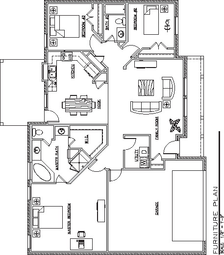
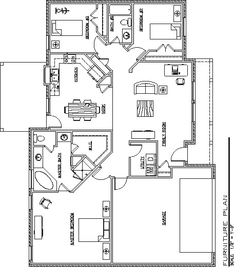
Project 10-5: House 1 Floor Plan with External References [ADVANCED]
1. Draw full size (without dimensions) the floor plan of house 1 (or use the one you drew previously) as shown in Figure 10-59. Use an 1/8″ architect’s scale to measure any features that do not have dimensions. The scale is 1/8″ = 1′-0″.

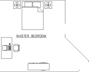
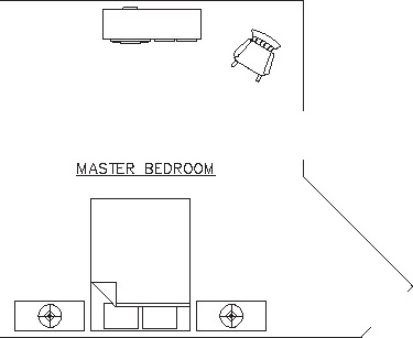
2. Draw full size the original xref master bedroom as shown in Figure 10-60. The scale of this figure is 1/4″ = 1′-0″. You will find most of the furniture and the computer in the Home - Space Planner drawing in the DesignCenter. Measure and draw the square lamp table and desk as shown.
3. Attach the original xref master bedroom to the house 1 floor plan as shown in Figure 10-61 and close the house 1 floor plan.
4. Make changes to the original master bedroom as shown in Figure 10-62. The scale of this figure is 1/4″ = 1′-0″. You will find most of the furniture in the Home - Space Planner drawing and in Autodesk Seek in the DesignCenter. Measure and draw the chests of drawers as shown.
5. Draw full size the original xref bedroom 2 as shown in Figure 10-63. The scale of this figure is 1/4″ = 1′-0″. You will find most of the furniture in the Home - Space Planner drawing and in Autodesk Seek in the DesignCenter. Use a 1/4″ architect’s scale to measure and draw the square lamp table.

6. Attach the original xref bedroom 2 to the house 1 floor plan (Figure 10-61) and close the house 1 floor plan.
7. Make changes to the original xref bedroom 2 as shown in Figure 10-64. The scale of this figure is 1/4″ = 1′-0″. Use a 1/4″ architect’s scale to measure and draw the rectangle on the south wall.

8. Draw full size the original xref bedroom 3 as shown in Figure 10-65. The scale of this figure is 1/4″ = 1′-0″. You will find the furniture in the Home - Space Planner drawing in the DesignCenter. Use a 1/4″ architect’s scale to measure and draw the square lamp table.

9. Attach the original xref bedroom 3 to the house 1 floor plan (Figure 10-61) and close the house 1 floor plan.
10. Make changes to the original xref bedroom 3 as shown in Figure 10-66. The scale of this figure is 1/4″ = 1′-0″. Use a 1/4″ architect’s scale to measure and draw the square lamp table. You will find the lamp, bed, and bicycle in the Home - Space Planner drawing and in Autodesk Seek in the DesignCenter.

11. Draw full size the original xref family room as shown in Figure 10-67. The scale of this figure is 1/4″ = 1′-0″. Use a 1/4″ architect’s scale to measure and draw the square lamp table. You will find the sofas and other items in the Home - Space Planner drawing in the DesignCenter.
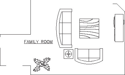
12. Attach the original xref family room to the house 1 floor plan (Figure 10-61) and close the house 1 floor plan.
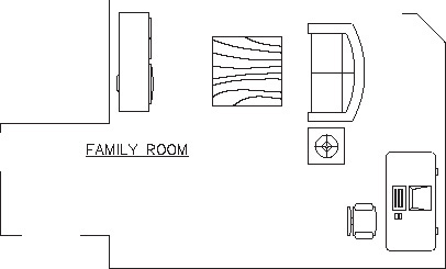
13. Make changes to the original xref living room as shown in Figure 10-68. The scale of this figure is 1/4″ = 1′-0″. Use a 1/4″ architect’s scale to measure and draw the square lamp table. You will find the remaining furniture in the Home - Space Planner drawing in the DesignCenter.
14. Open the house 1 floor plan. Your drawing should appear as shown in Figure 10-69.
15. Save the drawing in at least two places and print the drawing to scale.