Chapter 18
Presenting and Documenting 3D Design
Wireframe, hidden line, and shaded views are helpful means of visualizing models during the design process. However, visual styles leave something to be desired when you are communicating designs to your clients. The general public has come to expect designers to be able to produce the kind of realistic computer-generated imagery regularly seen in movies. This chapter will help you learn to do that by teaching you how to create realistic presentation images using the advanced rendering system in the AutoCAD® program. After you gain client approval, you still need to document your 3D design with relevant 2D plans, elevations, sections, and detail drawings so that your design can be communicated to the building or manufacturing trades. You will learn how to generate these drawings directly from models using AutoCAD 2014’s model documentation features.
- Assigning materials
- Placing and adjusting lights
- Creating renderings
- Documenting models with drawings
Assigning Materials
Materials describe the way objects interact with light. AutoCAD comes with an extensive library of real-world materials, including numerous types of concrete, metal, glass, brick, paint, leather, carpet, plastic, and so on. In the following steps, you will transfer materials from the Autodesk library to a sample model and then assign them to objects layer by layer:
2. Select the 3D Modeling workspace from the drop-down menu on the Quick Access toolbar.
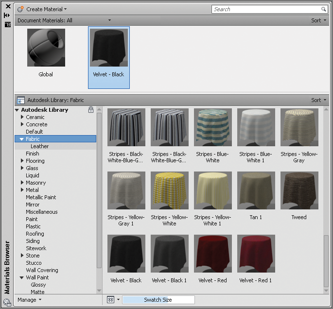
3. Select the ribbon’s Render tab, and click the Materials Browser toggle in the Materials panel. In the Materials Browser palette that appears, select the Fabric category in the Autodesk library, scroll down the list of materials in the right pane, and click Velvet – Black to load it into the document (see
Figure 18-2).
4. Continue loading materials by single-clicking the materials listed by category in
Table 18-1.
Table 18-1: Loading materials from the Autodesk library
| Flooring | Stone | Flagstone |
| Flooring | Stone | Flagstone Light Pink |
| Flooring | Wood | Natural Maple – Antique |
| Glass | Glazing | Clear |
| Masonry | Brick | Uniform Running – Burgundy |
| Metal | (none) | Chrome Satin 1 |
| Metal | Steel | Stainless – Brushed |
| Paint | (none) | Black |
| Plastic | (none) | Laminate Light Brown |
| Wall Paint | Matte | Cool White |
| Wall Paint | Matte | Flat – Antique White |
| Wood | (none) | Beech |
| Wood | (none) | Birch – Solid Stained Dark No Gloss |
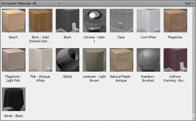
5. Figure 18-3 shows all the materials loaded into the current drawing. Close the Materials Browser.
All drawings have a global material (flat gray) by default.
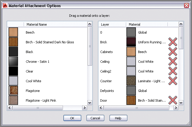
6. Expand the Materials panel, and select the Attach By Layer tool. Click the Layer header to sort the list of layers in reverse alphabetical order. Click the Layer header again to sort in alphabetical order. Drag materials from the left side, and drop them on the right side according to
Table 18-2.
Figure 18-4 shows the dialog box with all the necessary materials selected. Click OK to close the Material Attachment Options dialog box.
You can also assign materials by dragging them from the Materials Browser onto specific objects in the drawing canvas.
Table 18-2: Assigning materials to layers
| 0 | Global |
| Brick | Uniform Running – Burgundy |
| Cabinets | Beech |
| Ceiling | Cool White |
| Ceiling2 | Cool White |
| Counter | Laminate Light Brown |
| Defpoints | Global |
| Door | Birch – Solid Stained Dark No Gloss |
| Downlight | Cool White |
| Equip | Stainless – Brushed |
| Floor1 | Natural Maple – Antique |
| Floor2 | Flagstone |
| Floor3 | Flagstone Light Pink |
| Seat-Cushion | Velvet – Black |
| Seat-Frame | Chrome Satin 1 |
| Sink | Stainless – Brushed |
| Stairs | Birch – Solid Stained Dark No Gloss |
| Stool | Beech |
| Stove | Black |
| Table-Glass | Clear |
| Table-Legs | Chrome Satin 1 |
| Wall | Flat – Antique White |
| Wall2 | Flat – Antique White |
| Window-Frame | Cool White |
| Window-Glazing | Clear |
| Woodstove | Black |
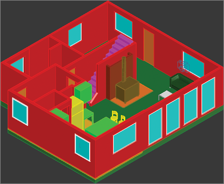
7. Texture maps do not normally appear in the viewport in the Shaded With Edges visual style. Select Realistic using the in-canvas Visual Style Controls menu.
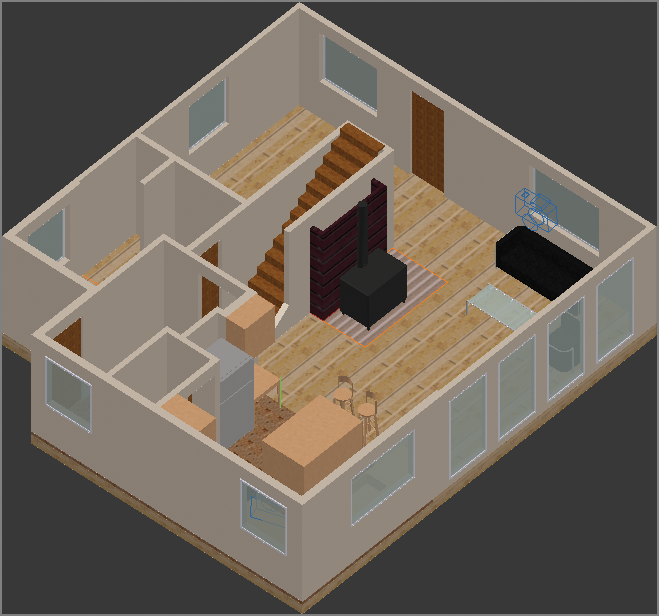
Figure 18-5 shows the texture maps in the viewport.
You can also display texture maps in the viewport by clicking Materials/Textures On in the Materials panel.
Texture maps are images used within materials to represent realistic surfaces.
8. Save your work as Ch18-B.dwg.
Placing and Adjusting Lights
Without light, nothing would be visible. AutoCAD uses what is called default lighting to illuminate objects in the viewport while you are building 3D models. The default lights are positioned behind the viewer and emit even illumination so that you can always see what is in the viewport. However, default lighting is not realistic and must be turned off as soon as you create artificial or natural light. You will add artificial lights (a series of spotlights mounted in the ceiling) and natural lights simulating the sun and sky light diffused throughout the atmosphere.
Adding Artificial Lights
In the real world, artificial lights are electrical lighting fixtures that are one of the hallmarks of the modern world. In AutoCAD, artificial lights include point, spot, and direct sources. Point sources illuminate in all directions, spot sources illuminate in a cone, and direct lights simulate light coming evenly from a particular direction, illuminating everything like the sun.
AutoCAD has two different lighting methods: standard and photometric. Standard lights were used before AutoCAD 2008, and they are still available so that lights in older DWG files will still be compatible in the current version.
However, I strongly urge you to use photometric lights, which are much more realistic. Photometric lights use real-world lighting intensity values (in American or International lighting units), and light coming from photometric light decays with the inverse square of distance, just as light does in the real world.
The absolute size of the model matters when you are using photometric lights. Natural light can easily overpower artificial light in terms of intensity.
In the following steps, you will first change lighting units to turn on the photometric lighting system, and then add a series of artificial lights to illuminate an architectural interior:
1. If the file is not already open, go to the book’s web page, browse to Chapter 18, get the file Ch18-B.dwg, and open it. Switch to the 3D Modeling workspace if it’s not selected already in the Quick Access toolbar.
AutoCAD for Mac users can change lighting units with the
UNITS command.
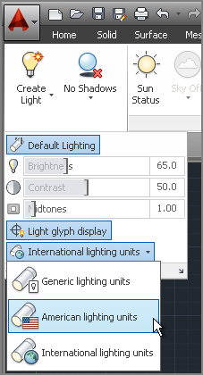
2. Select the ribbon’s Render tab, and expand the Lights panel. Open the menu that says Generic Lighting Units (used only for the standard lighting method), and select American Lighting Units (or International Lighting Units in metric).
Figure 18-6 shows this menu.
3. Click the word Top in the ViewCube to switch to a floor plan view. Choose Zoom Extents in the Navigation bar, and switch to the Wireframe visual style using the in-canvas control.
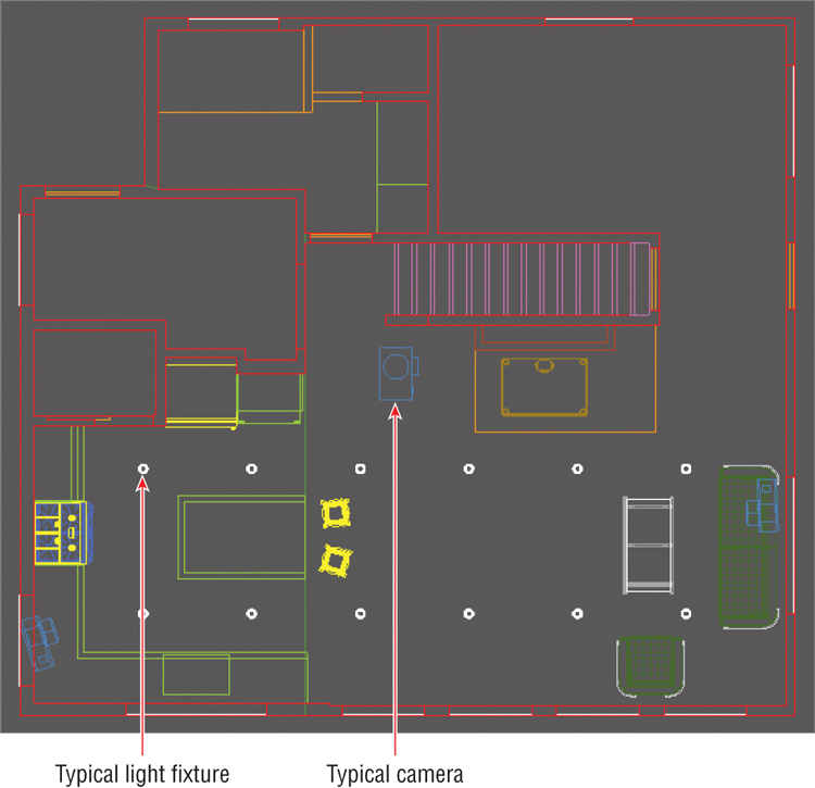
4. Select the ribbon’s Home tab, and expand the Layers panel. Select the Turn All Layers On tool. Light fixtures (down lights) are visible in the viewport (see
Figure 18-7).
5. Zoom in on the upper-left light by turning the mouse wheel forward. Do the following:
- If you’re a Windows user, select the ribbon’s Render tab and, on the Lights panel, open the Create Light menu and select Spot.
- If you’re a Mac user, type LIGHT, press Enter, type S (for Spot), and press Enter.
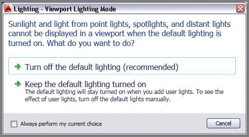
6. Select Turn Off The Default Lighting when the Lighting – Viewport Lighting Mode dialog box appears (see
Figure 18-8).
7. The command prompt reads:
Specify source location <0,0,0>:
Type .xy, and press Enter. Click a point visually centered on the light fixture (but do not use center object snap).
Point filters such as .xy, .xz, and .yz allow you to specify the listed coordinate values by clicking in the drawing. Typing the missing coordinate then specifies the 3D coordinates.
8. The command prompt now says
(need Z). Type
96 (the ceiling height), and press Enter. The command prompt now reads:
Specify target location <0,0,-10>:
Type .xy, press Enter, and click the same center point as you did in the previous step. The command prompt now says (need Z).
9. Type 0 (the floor height), and press Enter. Press Enter again to end the SPOTLIGHT command.
10. Press the F8 key if Ortho is not already on. Type CO (for Copy), and press Enter. Type L (for Last), and press Enter twice. Click a point near the light fixture, zoom out by turning the mouse wheel backward, move the cursor down to the light fixture in the bottom row, and click in the drawing canvas to create the second spotlight. Press Enter to end the COPY command.
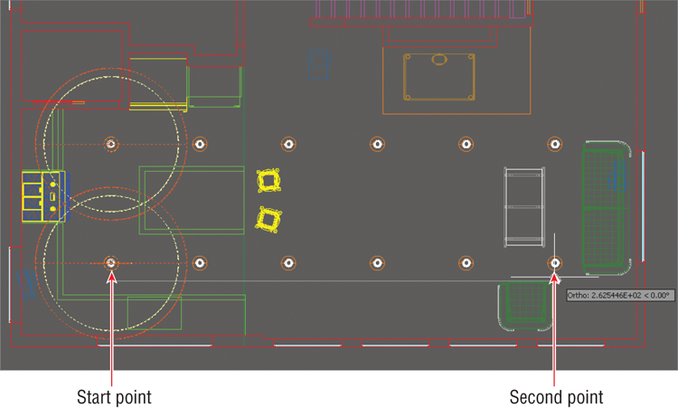
11. Press the spacebar to repeat the last command, type
P (for Previous), and press Enter. Type
L (for Last) so that you have a selection of two lights, and press Enter twice to end Select Objects mode. Click the start point under the last spotlight and zoom out. The command prompt reads:
Specify second point or [Array]
<use first point as displacement>:
Type A (for Array), and press Enter. Type 6 (for the number of items), and press Enter.
Placing lights within block definitions can help keep the source and fixture together.
12. Type
F (for Fit), and press Enter. Move the cursor under the rightmost light fixture (see
Figure 18-9), and click to specify the second point of the array. Press Enter to exit the
ARRAY command.
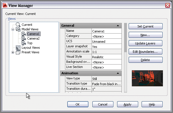
13. Type
V (for View), and press Enter. Double-click Camera 1 in the View Manager (see
Figure 18-10). Click Apply and OK.
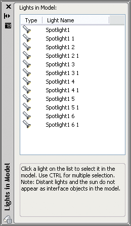
14. Click the Lights panel menu (a small icon in the lower-right corner of the Lights panel) to open the Lights In Model palette (see
Figure 18-11). Select the first spotlight in the list, hold Shift, and select the last spotlight in the list to select them all.
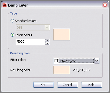
15. Right-click the selected lights in the Light Lister and choose Properties. Select the Lamp Color property, and click the icon to the right of the drop-down menu to open the Lamp Color dialog box. Select the Kelvin Colors radio button, type
5000, and press Tab. The resulting color changes (see
Figure 18-12). Click OK.
Real-world lamps are typically rated by a color standard and/or color temperature (measured in degrees Kelvin). The Tool palettes have a set of real-world lamps ready for use.
16. In the Properties palette, change Lamp Intensity to
15000, Hotspot Angle to
30, and Falloff Angle to
60.
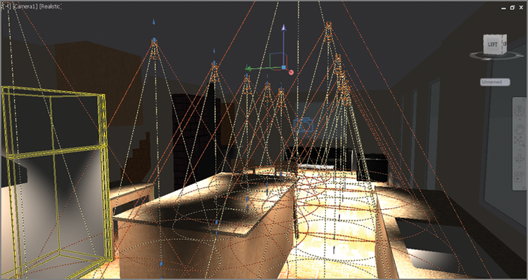
Figure 18-13 shows the resulting light glyphs in the drawing canvas. The outer orange cones represent the spotlight’s falloff angle and the inner yellow cones represent the area of full light intensity. Close the Properties and Lights In Model palettes. Press Esc to deselect all.
17. Save your work as Ch18-C.dwg.
The viewport shows direct illumination only. Reflected and transmitted light must be rendered.
Simulating Natural Light
AutoCAD can simulate the light of the sun and/or the light scattered in the sky by the atmosphere for any location on earth and for any time of year and time of day. In the following steps, you will configure the model to use a simulated sun and sky with specific time and space coordinates:
1. If the file is not already open, go to the book’s web page, browse to Chapter 18, get the file Ch18-C.dwg, and open it. Switch to the 3D Modeling workspace if it’s not selected already in the Quick Access toolbar.
Mac users control Sun Properties in the Properties inspector.
2. Select the ribbon’s Render tab if it is not already selected. Click the Sun Status toggle in the Sun & Location panel. The sun is on when the toggle is highlighted in blue.
The time zone is selected automatically in the Geographic Location dialog box, but you can adjust it if it is incorrect.
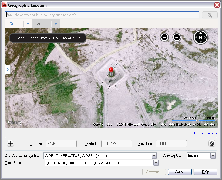
3. Select the Set Location tool in the Sun & Location panel. Select the From Map option. In the Geographic Location dialog box that appears, zoom into a hypothetical site anywhere in the world you would like. Right click the map and choose Drop Marker Here. A red pin appears on the map at that location (see
Figure 18-14).
4. Select Inches from the Drawing Unit drop-down menu and click Continue.
5. Click in the drawing canvas to select a reference point for the geolocation data. Type A and press Enter for the Angle option, and then type 90 and press Enter to specify the North direction as up. By specifying North on the plan you are establishing the building orientation on the map.
Dragging the Date and Time sliders automatically repositions the sun as it would in the real world at the chosen time coordinates.
6. Open the Sky Off menu in the Sun & Location panel, and select Sky Background And Illumination. AutoCAD automatically manages the color of the sky and degree of sky illumination based on your chosen time and space coordinates.
7. Save your work as Ch18-D.dwg.
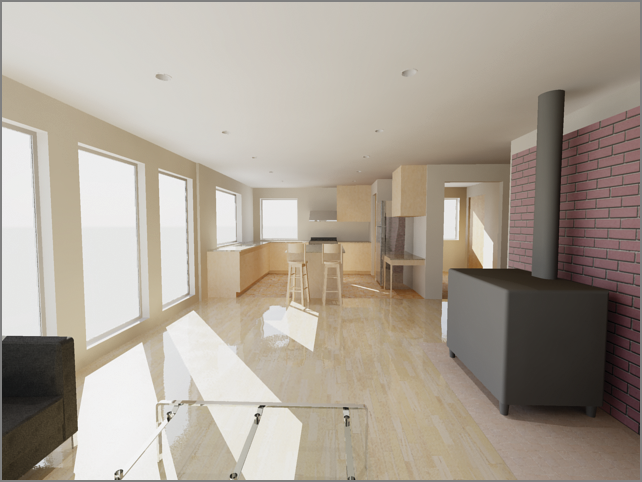
Creating Renderings
Rendering is the process of converting the geometry, materials, and lighting settings into pixels. Rendering can be a time-consuming process because it typically requires a lot of computation to perform. There are no rendering options in AutoCAD for Mac (just the RENDER command), and the resulting rendering quality isn’t as realistic as that available in AutoCAD for Windows, where you have many advanced options. In the following steps, you will use AutoCAD 2014’s advanced render settings for Windows to progressively create more realistic renderings:
1. If the file is not already open, go to the book’s web page, browse to Chapter 18, get the file Ch18-D.dwg, and open it. Switch to the 3D Modeling workspace if it’s not selected already in the Quick Access toolbar.
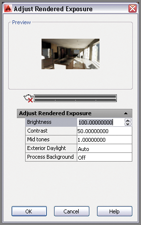
2. Select the ribbon’s Render tab, and expand its Render panel. Select the Adjust Exposure tool. After a few moments, AutoCAD creates a preview that gives you a rough sense of the level of illumination in a rendered thumbnail image. As it appears dark, change the Brightness from
65 to
100 and press Tab. The preview brightens significantly (see
Figure 18-15). Click OK to close the Adjust Rendered Exposure dialog box.
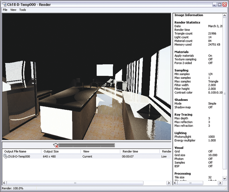
3. Open the Render Presets drop-down menu in the Render panel and select Low. Click the teapot icon to initiate the rendering process.
Figure 18-16 shows the resulting low-quality rendering that appears after a few moments in the Render dialog box.
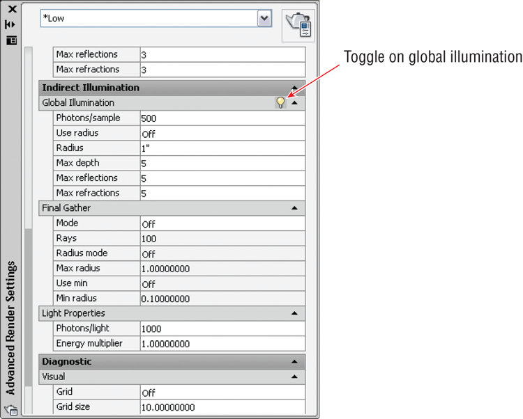
4. If you’re a Windows user, click the small icon at the right edge of the Render panel (or type
RPREF and press Enter) to open the Advanced Render Settings palette. Scroll down in the palette, and toggle on Global Illumination by clicking the lightbulb icon shown in
Figure 18-17. Mac users cannot adjust any advanced render settings.
Global illumination is best used in interior spaces to bounce light into areas that are not directly lit.
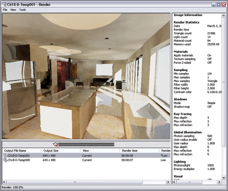
5. Click the Render icon in the Render panel to create another test render.
Figure 18-18 shows the result. The global illumination algorithm bounces photons off the floor, and this helps illuminate the ceiling. However, there aren’t enough photons for a quality result.
You will be prompted to install the Medium Images Library (700 MB) if it’s not already installed when you initiate a render. For the purposes of this book, you do not need to install it.
6. In the Advanced Render Settings palette, change the number of Photons/light to 10000. More photons will illuminate the dark recess of the architectural interior better. Click the Render icon in the Render panel to create another test render. It is much improved, but photon circles are still visible on various surfaces.
7. Open the Shadow menu in the Lights panel, and select Full Shadows.
Final gather can be used with or without global illumination. The final gather algorithm takes a lot of calculation (and thus time), but it produces the highest quality results.
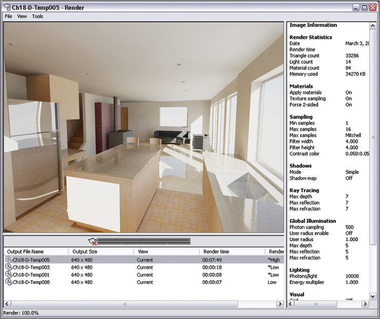
8. Open the drop-down menu at the top of the Advanced Render Settings palette and select High. Toggle on Global Illumination by clicking the lightbulb icon as you did in step 4. In the High preset, the scene will use final gather, which cleans up photon circles. Do the following:
- If you are a Windows user, click the Render button in the top-right corner of the Advanced Render Settings palette to initiate a render.
- If you are a Mac user, type RENDER, and press Enter.
9. Right-click the most recent output file name in the Render dialog box, and select Save in the context menu. In the Render Output File dialog box that appears, open the Files Of Type drop-down menu and select TIF (*.tif). Type Camera 1 in the File Name text box and click Save. Select the 24 Bits radio button in the TIF Image Options dialog box that appears and click OK.
10. Save your model as Ch18-E.dwg. Your work should now resemble the file of the same name, which is provided on the book’s web page.
Documenting Models with Drawings
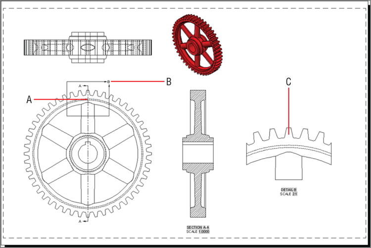
AutoCAD has a set of model documentation features that allow you to generate 2D plans, elevations, sections, and/or details directly from solid and surface models. In the following steps, you will open a 3D model of a gear and project multiple 2D drawings from it:
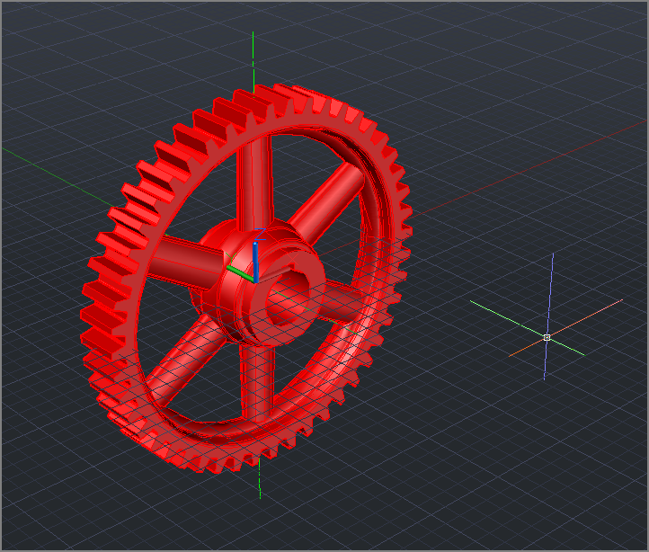
1. Open
Ch18-F.dwg. This is a 3D solid model of a gear (see
Figure 18-20).
2. Select the 3D Modeling workspace from the drop-down menu on the Quick Access toolbar. Select the ribbon’s Layout tab.
Model documentation drawings are created and dimensioned on layouts.
3. Select the Base tool in the Create View panel, and choose From Model Space in the drop-down menu. The command line reads:
Select objects or [Entire model] <Entire model>:
Select the gear object, and press Enter.
You can also link Autodesk Inventor base models into AutoCAD in order to generate dimensioned shop drawings.
4. The command line says:
Enter new or existing layout name to make current or [?] <24x36>:
In this case, there is already a layout called 24 × 36, so press Enter to accept this default layout. AutoCAD switches to the 24 × 36 layout, and you are prompted to specify a location for the base drawing. Click an arbitrary point in the lower-left corner of the layout (see
Figure 18-21).
5. The drawing is too small, so you will adjust its scale. The command line reads as follows:
Select option [select Orientation Hidden lines Scale Visibility
Move exit] <exit>:
Type S (for Scale), and press Enter. Type 1, and press Enter again. It just so happens that several views of the gear fit on the page with the gear at actual size.
6. Type 1:1 (or 1.0), and press Enter. Press Enter to accept the default Exit option, and you will see that the VIEWBASE command continues.
7. Click a point above the base plan drawing to locate a second projected view of the top of the gear.
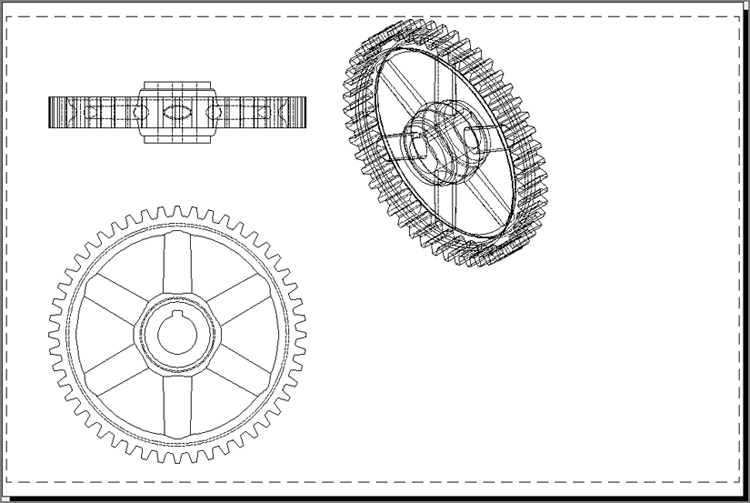
8. Click a third point at a 45-degree angle with respect to the base plan to locate an isometric projection, and press Enter to end the command. The drawings display in wireframe view showing hidden lines with a dashed linetype (see
Figure 18-22).
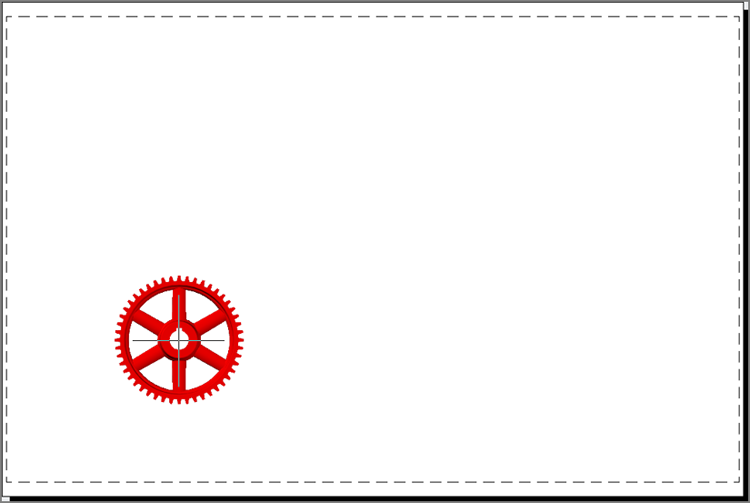
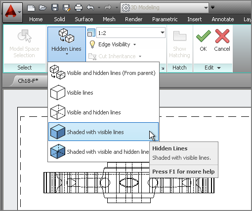
9. The isometric view is a bit large. Select it and you will see a red border appear around the view object. Click the Edit View tool on the Layout tab. On the temporary Drawing View Editor tab that appears, change the scale to 1:2. Open the Hidden Lines drop-down, and select Shaded With Visible Lines (see
Figure 18-23). Click OK in the Edit panel.
10. Click the Section tool in the Create View panel. The command line says:
Select parent view:
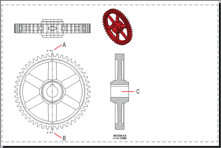
11. Click the original plan view you created in the lower left of the layout and press Enter. Click points A and B shown in
Figure 18-24 to draw a section cut line and press Enter. Click point C to locate the section view, and press Enter twice to end the
VIEWSECTION command.
You can move the view objects to arrange them on the layout.
12. Open the Detail drop-down on the Create View panel and select Rectangular. Toggle off object snap in the status bar. Select the original drawing of the gear as the parent view. Click points A and B shown in
Figure 18-25 to draw the detail area and press Enter. Click point C to locate the detail view, and press Enter to end the
VIEWDETAIL command.
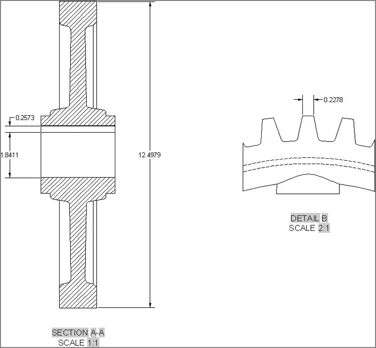
13. Toggle on object snap in the status bar. Switch to the Annotate tab on the ribbon, and select the Linear tool in the Dimensions panel. Dimension the features shown in
Figure 18-26. These dimensions are associated with the section and detail views, which in turn are associated with the base view, which is in turn associated with the model. If you were to change the gear geometry in modelspace, views and dimensions would automatically update on the layout.
14. Save your work as Ch18-G.dwg.
The Essentials and Beyond
In this chapter, you learned how to assign materials, create a photometric lighting simulation, place artificial lights, and assign space and time coordinates to sun and sky. In addition, you learned to create ever more realistic test renderings using global illumination and final gather algorithms to produce the highest-quality renderings. Finally, you created multiple views from a single 3D model for the purpose of documentation.
Additional Exercise
Render the Camera 2 view on your own. Change any of the materials or lights as you see fit to show off the space. Congratulations on completing all the exercises in this book!