Chapter 3
Using Drawing Aids
The drawing aids in the AutoCAD® program are like the triangles, compasses, and engineering scales of traditional drafting. Drawing aids are essential modes and methods of entering data that, once mastered, allow you to create measured drawings with ease. I highly recommend learning all of the drawing aids, because they will make you a more productive draftsperson. Most drawing aids can be toggled on or off from the application status bar. Additional settings and dialog boxes are accessible by right-clicking the individual status bar toggles.
- Grid and Snap
- Ortho and Polar Tracking
- PolarSnap
- Running object snaps
- From snap
- Object snap tracking
Grid and Snap
The most basic drawing aid, Grid, makes the canvas in AutoCAD look like graph paper. You can adjust the grid’s measured size and the spacing of its major lines to simulate many types of graph paper.
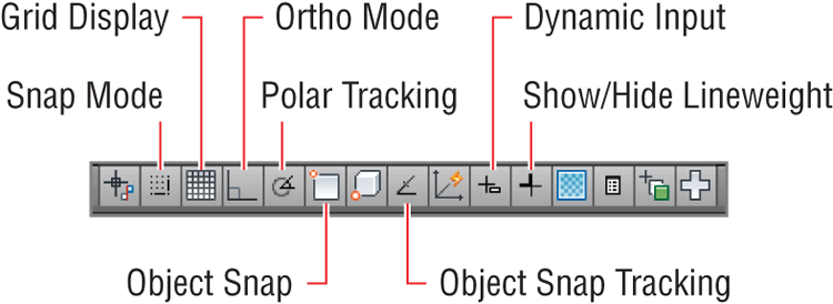
Snap constrains your ability to draw objects so that they automatically start and end precisely at grid intersections. Grid and Snap are most helpful when used together so that you can draw objects that snap to the grid. Figure 3-1 shows some of the status bar toggles that you’ll be learning about in this chapter.
In the following steps, you will experiment with Grid and Snap by drawing lines using these aids:
1. Click the New button on the Quick Access toolbar.
2. Choose the acad.dwt Imperial template (or acadiso.dwt metric template) from the Select Template dialog box and click Open.
Grid spacing is usually equal to or an increment of the snap interval.
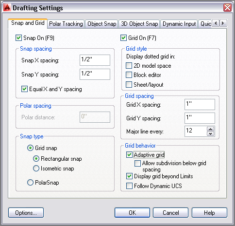
3. Right-click the Grid Display toggle on the status bar, and choose Settings from the context menu. Change Grid X spacing to 1″ (or 10 mm), and press Tab; Grid Y spacing updates with the same value. Set Major Line Every to 12 for Imperial (or 10 for metric) so that you’ll see darker grid lines every foot. Notice that Snap spacing is set to 1/2″ (or 10 mm) by default. Select Snap On, and verify that the Grid Snap radio button is selected in the Snap Type area (see
Figure 3-2). Click OK.
4. Click the Line tool in the Draw panel on the ribbon’s Home tab. Click the first point near the lower-left corner of the canvas at the intersection of major grid lines (darker lines). Click the second point 2′ (or 609 mm) above the first point by clicking the second intersection (or sixth intersection in metric) of major grid lines. Right-click to end the LINE command. It’s very difficult to see the line because the grid obscures it.
5. Click the Show/Hide Lineweight icon in the status bar so that the button is highlighted in blue. It’s difficult to see the line because the default lineweight display is too thin.
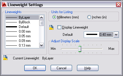
6. Right-click the Show/Hide Lineweight icon, and choose Settings from the context menu. Open the Default drop-down list, select 0.016″ (or 0.40 mm) (see
Figure 3-3), and click OK. The line you drew in step 4 is displayed thicker so that it’s more visible against the grid.
You’ll learn how to control lineweight with layers in Chapter 6, “Controlling Object Visibility and Appearance.”
7. Type
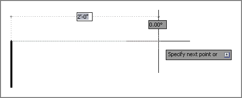
L, and press Enter twice to continue drawing from the last point clicked. Toggle Grid Display off and Dynamic Input on in the status bar. Move the cursor horizontally to the right from the point at which the rubberband is anchored. Notice that 1/2″ (or 10 mm) increments are all that show up on screen; this is due to Snap. Snap can be used independently of the grid; the grid is merely a visual drawing aid. Click on the drawing canvas when the dynamic input value reads 2′-0″ (or 600 mm), as shown in
Figure 3-4. Leave the file open for work in the next section.
Transparent Commands
Status bar buttons can be toggled on or off and their settings adjusted while another command is running. Commands that operate while another command is running are called
transparent commands. Typing a single quote before a command forces it to be run transparently. For example, while drawing a line, type
'z and press Enter. The
ZOOM command is run transparently and, when it is done, the
LINE command resumes. The following transcript shows this command sequence:
Command: l
LINE Specify first point: 'z
'ZOOM
>>Specify corner of window, enter a
scale factor (nX or nXP), or
[All/Center/Dynamic/Extents/Previous/
Scale/Window/Object] <real time>:
>>>>Specify opposite corner:
Resuming LINE command.
Specify first point:
Ortho and Polar Tracking
Ortho mode aids in drawing orthogonal (horizontal or vertical) lines. Polar Tracking is more flexible than Ortho mode, with the ability to constrain lines to increments of a set angle. A list of common angles is included on Polar Tracking’s context menu, such as 45°, 30°, 22.5°, 10°, and so on. The traditional square and a set of triangles from traditional drafting are analogues to Ortho and Polar Tracking modes in AutoCAD.
When Polar Tracking is set to 90, it functions identically to Ortho mode.
Let’s try Ortho and Polar Tracking modes by drawing a series of line segments. You’ll use Ortho when the segments are 90° apart and Polar Tracking when the segments are drawn at other angles.
1. Type L, and press Enter twice to continue drawing from the last point.
2. Toggle off Snap mode by pressing the F9 key.
3. Toggle on Ortho mode by pressing the F8 key.
The dash is a necessary separator between whole and fractional inches.
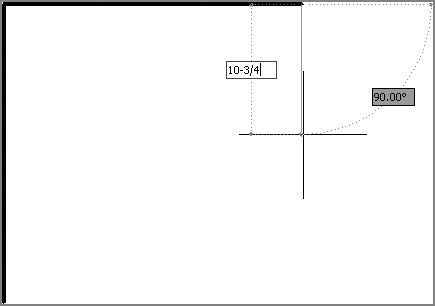
4. Move the cursor down from the last point, type
10-3/4″ (or
240 in metric), and press Enter. Ortho mode constrains the line vertically and typing in an explicit value obviates the need for Snap (see
Figure 3-5). You don’t have to use the comma from Cartesian coordinates or the angle symbol from polar coordinates with direct distance entry.
5. Toggle off Ortho mode by clicking its status bar button. Toggle on Polar Tracking by clicking the adjacent button on the right. Right-click the Polar Tracking button, and choose 45.00 from the context menu.
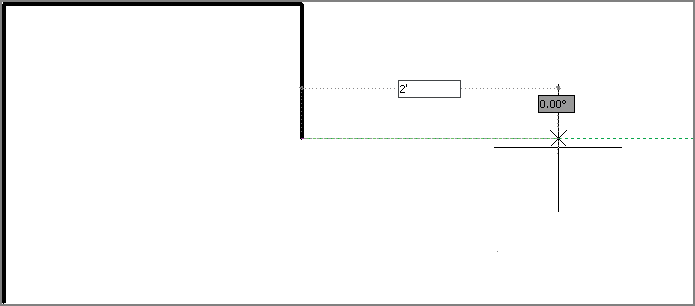
6. Move the cursor around, and observe that green dashed lines appear in eight locations around a circle (in 45° increments). Move the cursor to the right relative to the last point, type
2′ (or
600 in metric), and press Enter (see
Figure 3-6). Press Esc to terminate the
LINE command without deleting the last segment drawn.
7. Save your work as Ch3-B.dwg (or Ch3-B-metric.dwg).
Just like Ortho mode, Polar Tracking guarantees that the last line drawn was perfectly aligned to the set increment; you merely had to move the cursor in the general direction you wanted to direct the new line. Ortho and Polar Tracking save you from having to type in angles or coordinate values explicitly, or to even think about coordinate systems.
PolarSnap
PolarSnap includes a kind of snap that is customized for Polar Tracking. Instead of being tied to a spatial grid (as with Snap), PolarSnap is appropriately based on relative polar coordinates. As you’ll see in the steps that follow, PolarSnap is useful for drawing measured lines on angles other than horizontal or vertical.
1. If the file is not already open from the previous step, go to the book’s web page at
www.sybex.com/go/autocad2014essentials, browse to Chapter 3, download the file
Ch3-B.dwg (or
Ch3-B-metric.dwg), and open it.
2. Toggle on Snap by clicking its icon on the status bar. Right-click the same button, and choose Settings from the context menu.
3. Select the PolarSnap radio button in the Drafting Settings dialog box. Type
1″ (or
10 in metric) in the Polar Distance text box (this dialog was shown back in
Figure 3-2). Click OK.
The PolarSnap increment defaults to the Snap X spacing value unless a Polar Distance value is entered.
4. Type L, and press Enter twice to continue drawing from the last point.
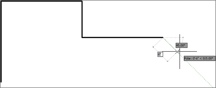
5. Move the cursor down at a 45° angle from East, and observe the Snap values that appear with Dynamic Input on screen. Click when the value is 6″ (or 150 mm) (see
Figure 3-7). You avoided having to type anything with Polar Tracking and PolarSnap.
6. Move the cursor down, and click to draw a line when the value reads 1′ (or 300 mm). Right-click to end the LINE command.
7. Press the spacebar to repeat the LINE command. Hold down Shift, and right-click to access the Snap context menu. Select Endpoint in the menu, and click the lower endpoint of the first line you drew in this exercise.
8. Toggle off Snap mode by clicking its icon on the status bar, thus disabling PolarSnap.
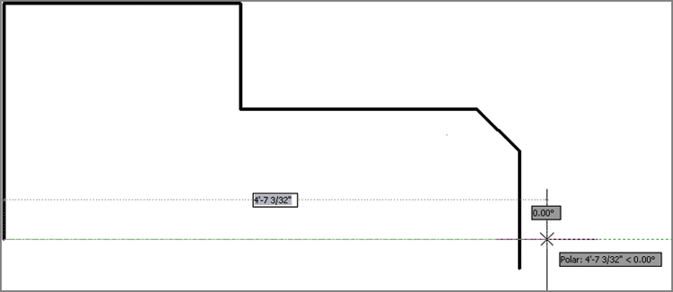
9. Move the cursor horizontally to the right until it overshoots the last line drawn in step 5. Click to draw the line without worrying about its length (see
Figure 3-8). Right-click to complete the command.
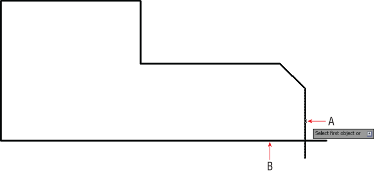
10. Type
F (for Fillet), and press Enter. Verify that Radius is set to 0 in the Command window, and then click the vertical and horizontal lines on the portions of the lines that you want to keep (marked A and B in
Figure 3-9). The drawn shape forms a closed loop.
11. Save as Ch3-C.dwg (or Ch3-C-metric.dwg), which is available for download among the files at the book’s web page.
Running Object Snaps
The lines you have drawn thus far are all precisely connected because they were chained together as they were drawn. In other words, the last point of one segment was reused as the first point of the next segment. Aside from this special circumstance, lines must be connected using object snaps to ensure accuracy.
You learned to use the Object Snap context menu in Chapter 2, “Basic Drawing Skills,” and now you will use that as a jumping-off point to learn a far more efficient method called running object snap. As you will see in the steps that follow, with running object snaps, frequently used object snaps can be turned on continuously. That way, you don’t have to invoke them explicitly every time you want to use object snaps.
1. If the file is not already open from performing the previous step, go to the book’s download page at
www.sybex.com/go/autocad2014essentials, browse to Chapter 3, download the file
Ch3-C.dwg (or
Ch3-C-metric.dwg), and open it.
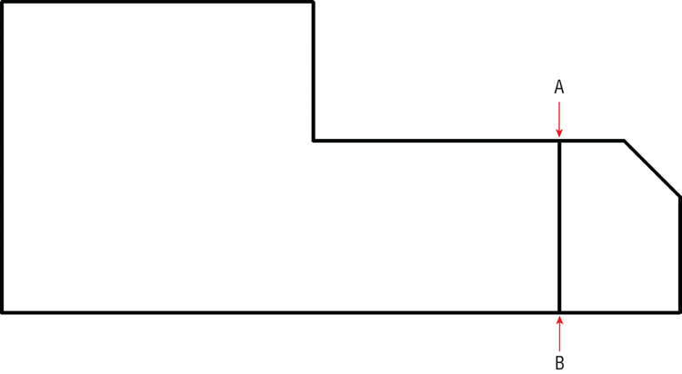
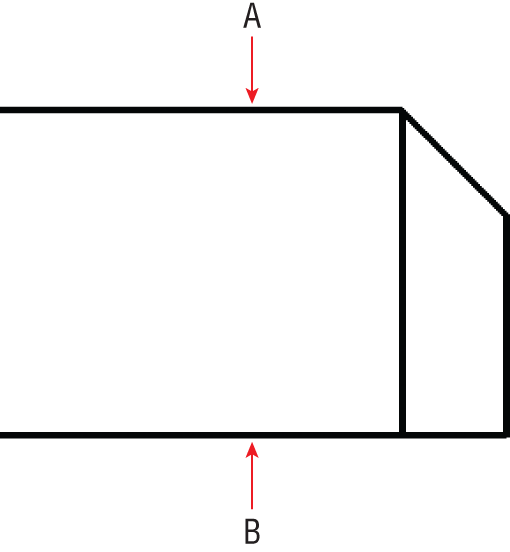
2. Using Polar Tracking, but without invoking Object Snap, draw a line using points A to B in
Figure 3-10 as a guide. Click each point as accurately as you can because I want you to see that you can’t make it perfect without using Object Snap.
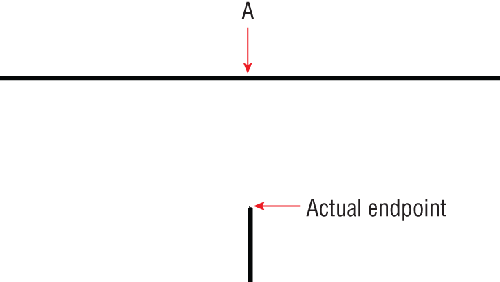
3. Press
Z and then Enter. Click two points to define a tightly cropped zoom window around point A. Zoom in again if necessary until you can see that the endpoint of the line you just drew is not on the horizontal line (see
Figure 3-11). No matter how carefully you clicked point A in the previous step, the line you drew will not be on the edge (it will either fall short of it or overshoot it).
4. Select Zoom Previous from the Navigation bar’s Zoom menu. Click Zoom Previous again if necessary to return to the original view.
5. Click the line drawn in step 3, and press the Delete key.
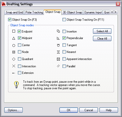
6. Toggle on Object Snap on the status bar. Right-click the same icon, and choose Settings from the context menu. Click the Clear All button, and then select Endpoint, Midpoint, and Perpendicular (see
Figure 3-12). Click OK.
You can toggle on one object snap type at a time using the Object Snap icon’s context menu. Choose Settings to make more extensive Snap selections.
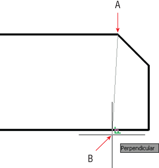
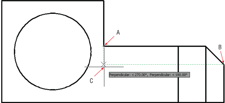
7. Toggle off Polar Tracking and Dynamic Input modes on the status bar. Click the Line tool on the Draw panel. Move the cursor close to point A in
Figure 3-13, and wait for the green endpoint marker to appear. When it does, click to snap the first point of your line precisely to this point.
8. Move the cursor down to point B, and wait until the green perpendicular marker appears. When it does, click the drawing canvas to select the second point. Press Esc to end the command. This line is connected precisely at both ends because Object Snap was used.
You don’t have to try to position the cursor over the actual geometric perpendicular; as long as the perpendicular marker appears, AutoCAD will calculate the desired point exactly.
9. Zoom into point A or B in
Figure 3-14, and verify that the lines are connected perfectly. Click Zoom Previous in the Navigation bar to return to the initial overall view.
10. Type
L, and press Enter. Hold Shift down, right-click to open the Object Snap context menu, and choose Nearest. Object snaps invoked from the context menu override any running object snaps. Click point A, shown in
Figure 3-14. Nearest ensures that the new line is attached somewhere along the edge of the horizontal line.
Nearest should be used with caution as a running snap mode because it conflicts with other snap modes. Choosing None in the Snap context menu overrides any running snaps (with no snap).
11. Move the cursor close to point B, as shown in
Figure 3-14, and click when the perpendicular marker appears. Press Esc to end the
LINE command.
12. Save your work as Ch3-D.dwg (or Ch3-D-metric.dwg).
From Snap
Rather than snapping to an existing geometrical feature (such as an endpoint, midpoint, intersection, and so on), how do you snap a set distance and direction from one? Answer: Use the From snap, as shown in the following steps:
1. If Ch3-D.dwg (or Ch3-D-metric.dwg) is not still open from the previous section, go to the book’s web page and open the document from the Chapter 3 file.
2. Type L and press Enter. Hold Shift and right-click to open the Object Snap context menu. Select From in the context menu.
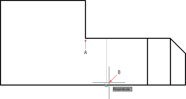
3. Click point A shown in
Figure 3-15. This is the point from which you will specify a displacement. Type
@6″<0 (or
@150<0 for metric) to specify the displacement to the first point of the line and press Enter.
4. Move the cursor to point B, and wait for the running perpendicular snap marker to appear. When it does, click to specify the second point of the line. Press Esc to end the LINE command. You’ve drawn a line exactly 6″ (or 150 mm) over from the corner.
5. Select the line you just drew, and press the Delete key.
6. Save your work as Ch3-E.dwg (or Ch3-E-metric.dwg).
Object Snap Tracking
Object snap tracking is for situations where you want to snap to a point that has a geometric relationship with two or more snap points. As you’ll see in the following steps, using object snap tracking saves time when compared with drawing temporary construction lines that must later be deleted.
1. If Ch3-E.dwg (or Ch3-E-metric.dwg) is no longer open from the previous section, go to the book’s web page and open the document from the Chapter 3 folder.
2. Click the Circle tool on the Draw panel.
3. Toggle on Object Snap Tracking by clicking its icon on the status bar. Verify that Ortho mode is on by looking at the status bar. (If it isn’t, press F8.)
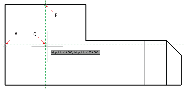
4. Move the cursor over point A, as shown in
Figure 3-16. When the running midpoint snap marker appears, move the cursor horizontally to the right to establish the first tracking line. Do not click yet.
5. Move the cursor over point B in
Figure 3-16, and wait for the Midpoint marker to appear. Move the cursor down vertically to establish the second tracking line. Again, do not click yet.
6. Move the cursor down until both tracking lines intersect. When they do, click to set the center point of the circle. Type 9 (or 220 for metric), and press Enter to create a circle with a radius of 9″ (or 220 mm).
7. Click the Rectangle tool on the Draw panel. Move the cursor over the endpoint marked A in
Figure 3-17 and, without clicking, move the cursor down to establish the first tracking line.
8. Move the cursor to point B in
Figure 3-17 to track another endpoint. Move the cursor horizontally back to the intersection with the first tracking line, and click to establish the first corner of the rectangle (point C).
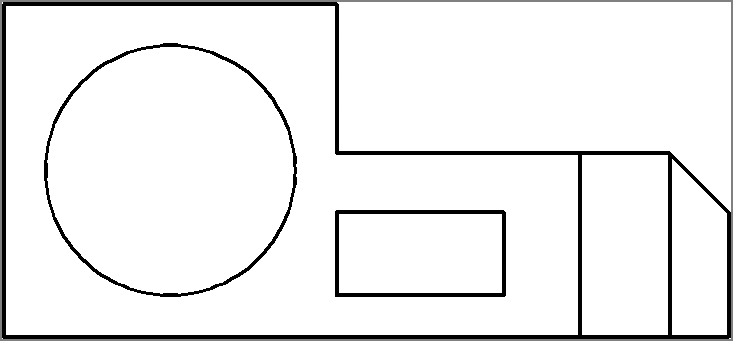
9. Type
@1′,-6 (or
@280,-160 for metric), and press Enter. The rectangle and drawing is complete (see
Figure 3-18).
10. Toggle off Show/Hide Lineweight.
The Essentials and Beyond
You have learned how to draw accurately using a variety of drawing aids, including Grid and Snap, Ortho mode and Polar Tracking, PolarSnap, running object snaps, From snap, and object snap tracking. Each of these aids will become second nature to you as you continue practicing drawing in AutoCAD. In time, you will know which drawing aid most efficiently fits each geometric situation you encounter.
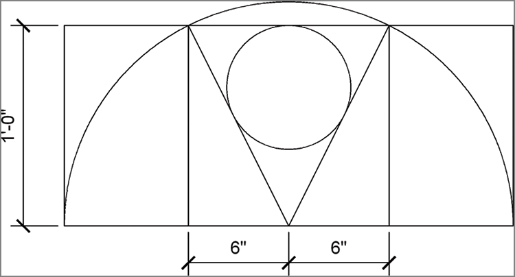
Additional Exercise
- Draw the following diagram to the given dimensions. You will need to employ a variety of drawing aids learned in this chapter to draw the figure accurately.