Chapter 13
Working with Layouts and Annotative Objects
There are two distinct spaces in which you can create drawings: modelspace and paperspace. Typically, 2D drawings and 3D models are created in modelspace. Layouts in paperspace bring together annotations and drawings ultimately to be plotted on paper or published electronically. Viewports display drawings at specific scales on layouts, which is where you’ll draw title blocks that frame the drawings. You will learn about all of them in this chapter and how to use each.
- Creating annotative styles and objects
- Creating layouts
- Adjusting floating viewports
- Overriding layer properties in layout viewports
- Drawing on layouts
Creating Annotative Styles and Objects
All the geometry you draw in the AutoCAD® program is created at its actual size. However, the heights of text, dimensions, and attributes present a potential problem. As drawings are scaled down from their real-world size to be represented on paper using viewport scale (which you’ll learn more about in the “Adjusting Floating Viewports” section later in this chapter), text, dimensions, and attributes are likewise scaled down to fit on paper.
To compensate, users of versions before AutoCAD 2008 intentionally had to scale text, dimensions, and attributes much larger in modelspace than their intended size on paper so that, when reduced in a viewport, they appeared at the correct size on paper. Complicating this issue is the fact that, if you wanted to display the same drawing at different scales on the same sheet of paper (a common occurrence), you would have to duplicate all the annotation, assign copies to different layers, and scale the annotation according to each viewport’s scale.
Fortunately, annotative objects overhaul and greatly simplify this process by automatically displaying text, dimensions, and/or attributes at different heights on the same drawing according to the viewport scale in which they are displayed.
The purpose of annotative styles is to control the appearance of annotative objects such as text, dimensions, and/or attributes. I will discuss both text and dimensions in upcoming sections, but will hold off on attributes until Chapter 15, “Storing, Presenting, and Extracting Data.” As you’ll see, annotative objects change their sizes automatically to fit the drawing scale.
Working with Annotative Text
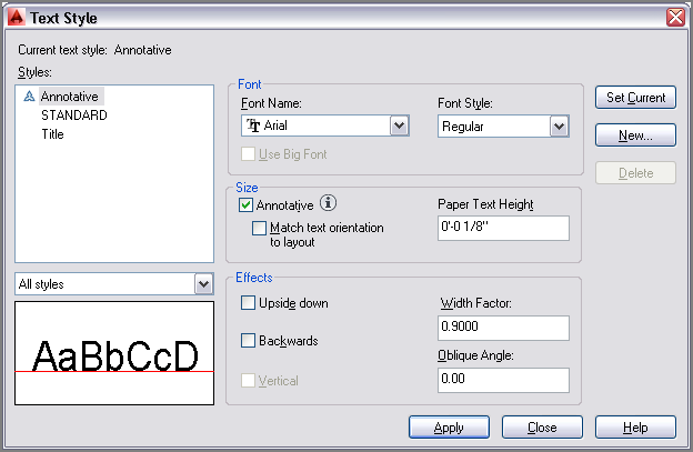
In the following steps, you will configure an annotative text style to display text at 1/8″ (or 0.4 cm) high on paper. All the text objects assigned to this style will automatically adjust their heights to 1/8″ (or 0.4 cm) no matter in what scale the drawing is shown. In this way, annotative objects automatically change their sizes relative to other geometry in the drawing.
2. Type ST (for Style), and press Enter. Click the New button in the Text Style dialog box that appears. Type Annotative as the style name in the New Text Style dialog box and click OK.
3. Select Arial as the font name, select Annotative in the Size area, type
1/8″ (or
0.4 cm) for Paper Text Height, and type
0.9 for the Width Factor (see
Figure 13-1). Click Apply, and then click Close.
4. Select Zoom Realtime from the Navigation bar, and zoom into the room with the round table at the top of the floor plan by dragging upward.
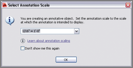
5. Click the Multiline Text tool in the Annotate panel on the ribbon’s Home tab. Select 1/16″ = 1′-0″ (or 1:200 for metric) from the drop-down menu in the Select Annotation Scale dialog box that appears (see
Figure 13-2). Click OK.
If you don’t see the Select Annotation Scale dialog box (it can be suppressed), you can still set the annotation scale on the status bar.
6. Click the first corner at some arbitrary point inside the round table. Type
J (for Justify), and press Enter. The command prompt reads:
Enter justification [TL TC TR ML MC MR BL BC BR] <TL>:
Type MC (for Middle Center), and press Enter. Click the second point a short distance down and to the right. Type Conference Room, and press Ctrl+Enter to end the MTEXT command. Pressing Enter moves you to the next line in multiline text, so you must hold Ctrl while pressing Enter to end the command.
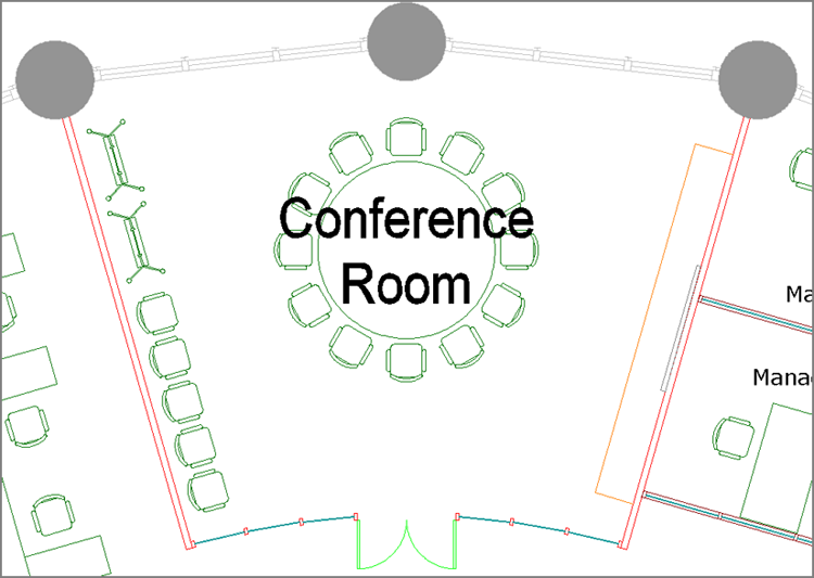
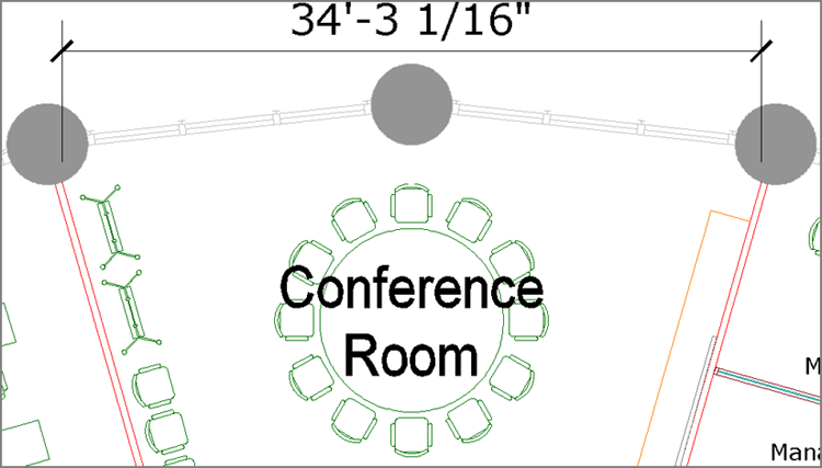
7. Click the Move tool on the Modify panel, type
L (for Last), and press Enter twice. Type
INS (for Insert), and click the text object. Type
CEN (for Center), hover the cursor over the circle, and press Enter. Click the circular table to center the text on the table (see
Figure 13-3). This text appears 1/8″ high in 1/16″ = 1′-0″ scale (or 0.4 cm high in 1:200 scale).
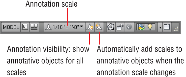
8. Select the two toggles adjacent to Annotation Scale on the status bar so that both have yellow icons indicating that they are turned on (see
Figure 13-4).
9. Change the Annotation Scale to 1/2″ = 1′-0″ (or 1:20 for metric) in the status bar. The text you created appears much smaller. This text will appear 1/8″ high in 1/2″ = 1′-0″ scale (or 0.4 cm in 1:20 scale). Select the text object, and observe both scales simultaneously (see
Figure 13-5). Press Esc to deselect.
10. Save your work as Ch13-B.dwg or Ch13-B-metric.dwg.
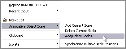
Annotation Scales
Annotative objects do not automatically hold representations at all conceivable scales. You can add or delete scales for individual annotative objects in the right-click context menu.
Working with Annotative Dimensions
In much the same way as text, dimensions can be made annotative so that they change sizes when the annotative scale is changed. In the following steps, you will explore how to do this by creating an annotative dimension style and then adding an annotative linear dimension:
1. If the file is not already open from performing the previous step, go to the book’s web page, browse to Chapter 13, get the file Ch13-B.dwg or Ch13-B-metric.dwg, and open it.
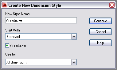
2. Type
D (for Dimension Style), and press Enter. Click the New button in the Dimension Style Manager to bring up the Create New Dimension Style dialog box. Type
Annotative in New Style Name, and click the Annotative check box (see
Figure 13-6). Then do the following:
- If you are using Imperial units, click Continue, OK, and then Close.
- If you are using metric units, click OK, select Decimal Units and Precision of 0 (whole centimeters) on the Primary Units tab of the Modify Dimension Style dialog box, click OK, and click Close.
Annotative styles can have any name. What makes a style annotative is the check box in the Create New Dimension Style dialog box.
3. Toggle on Object Snap. Verify that endpoint running object-snap mode is on by right-clicking the icon in the status bar.
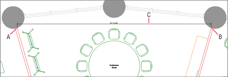
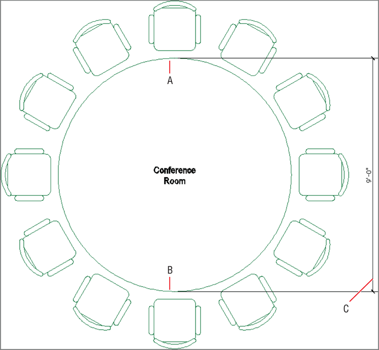
4. Click the Linear dimension tool in the Annotate panel. Click points A, B, and C, as shown in
Figure 13-7.
5. Select the 1/16″ = 1′-0″ (or 1:200 in metric) scale button in the Annotation Scale menu on the status bar. A much larger dimension object appears in the drawing canvas. Select the dimension object and, using one of the dimension line grips at either end of the dimension line, move it upward so that the dimension has longer extension lines. Press Esc to deselect.
Figure 13-8 shows the result.
Each scale’s versions of annotative text and dimensions are separate objects, which should be adjusted independently with grips for clarity.
6. Save your work as Ch13-C.dwg or Ch13-C-metric.dwg.
Creating Layouts
Think of layouts as sheets of virtual paper because that’s what they represent. You will create layouts whether you ultimately plan to publish the drawing on paper or in electronic form. Each drawing can have multiple layouts to publish in a variety of formats. In the following steps, you will create two layouts, one for an 8.5″ × 11″ sheet of paper (or ISO A4) and another for a 30″ × 42″ drawing (or ISO A0), which are standard business and drawing sizes:
1. If the file is not already open, go to the book’s web page, browse to Chapter 13, get the file Ch13-C.dwg or Ch13-C-metric.dwg, and open it.
2. Click the Layer Properties tool in the Layers panel on the ribbon’s Home tab.
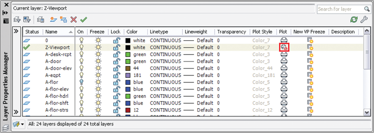
3. Click the New Layer button in the Layer Properties Manager that appears. Type
Z-Viewport, and press Enter. With the Z-Viewport line still highlighted, press Alt+C to make the new layer current. Click the printer icon in the Z-Viewport layer’s Plot column to make this layer nonplotting (see
Figure 13-9). Close the Layer Properties Manager.
Layout and Model Tabs
Layout and model tabs are a legacy interface that longtime AutoCAD users may prefer to keep using. If you see tabs at the bottom of the drawing canvas labeled Model and Layout1, then you are looking at the older interface. Right-click either of these tabs, and choose Hide Layout And Model Tabs to use the more streamlined, modern interface.
Paperspace is a 2D space representing a sheet of virtual paper. Modelspace is a 3D space containing both 2D drawings and 3D models.
4. If layout tabs are displayed, click the Layout1 button. If the layout tabs are hidden, click the Quick View Layouts button and then click Layout1 on the status bar or the Layout1 tab on the lower edge of the drawing window.
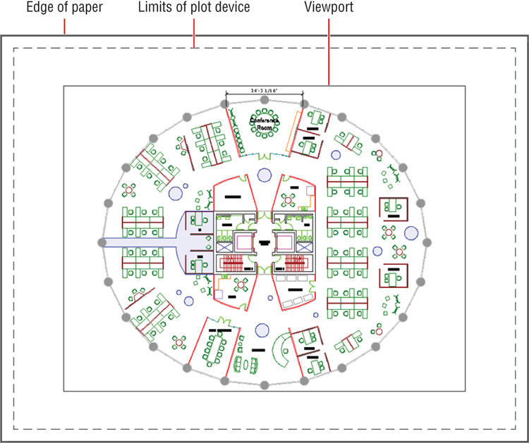
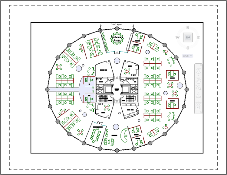
The image in the drawing canvas changes as you enter paperspace: A white representation of paper is displayed with an automatically created viewport through which you can see the drawing in modelspace. The viewport object is on the Z-Viewport layer. The viewport frame will not appear in the output because it is on a nonplotting layer. The contents of the viewport will be output, however. The dashed lines indicate the limits of the plotting device’s printable area (see
Figure 13-10).
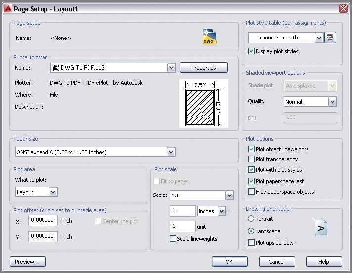
5. Select the ribbon’s Output tab. Click the Page Setup Manager tool in the Plot panel, and click the Modify button in the Page Setup Manager dialog box that appears. When the Page Setup: Layout1 dialog box opens, select the DWG To PDF.pc3 plotter from the Name drop-down, choose monochrome.ctb from the Plot Style Table drop-down, check Display Plot Styles, and do the following:
- If you are using Imperial units, select ANSI Expand A (8.50 × 11.00 Inches) as the paper size (see Figure 13-11). Leave the plot scale at 1 inch = 1 unit. Click OK, and then click Close.
- If you are using metric units, select ISO Full Bleed A4 (297.00 × 210.00 MM) as the paper size. Set the plot scale to 10 mm = 1 unit. Click OK, and then click Close.
Available paper sizes are dependent on the plotter selection.
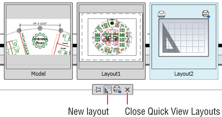
6. Click Quick View Layouts in the status bar. Click the New Layout icon at the bottom of the Quick View Layouts interface that appears at the bottom of the drawing canvas. Click Layout2 to open it (see
Figure 13-12). Click the Close Quick View Layouts icon.
7. Click the Page Setup Manager in the Plot panel. Click the Modify button in the Page Setup Manager dialog box that appears to modify Layout2. Select the DWG To PDF.pc3 plotter, select monochrome.ctb from the Plot Style Table drop-down, and check Display Plot Styles. Then do the following:
- If you are using Imperial units, select ARCH E1 (30.00 × 42.00 Inches) as the paper size. Leave the plot scale at 1 inch = 1 unit. Click OK, and then click Close.
- If you are using metric units, select ISO A0 (841.00 × 1189.00 MM) as the paper size. Set the plot scale to 10 mm = 1 unit. Click OK, and then click Close.
8. A single tiny viewport was automatically created on the current layer in the corner of the layout. You will configure this viewport in the next section and create an additional viewport. Save your work as Ch13-D.dwg or Ch13-D-metric.dwg.
Adjusting Floating Viewports
Think of floating viewports as windows that exist in paperspace through which one sees into modelspace. Viewports are termed floating because you can position and size their frames however you like in relation to the paper represented in a layout. You will configure a single floating viewport on Layout1 and two separate viewports on Layout2 to gain experience with viewports.
Working on Layout1
In the following steps, you will set the scale of the building floor plan on Layout 1 and then adjust its viewport to fit the floor plan:
1. If the file is not already open, go to the book’s web page, browse to Chapter 13, get the file Ch13-D.dwg or Ch13-D-metric.dwg, and open it.
2. Click the Quick View Layouts icon on the status bar. Select Layout1, and then press Esc to exit Quick View Layouts mode.
3. Click the PAPER icon on the status bar. This icon toggles between paperspace and modelspace, and the word displays which space you are currently in (now modelspace). The viewport’s frame highlights with a thicker representation when displaying modelspace (see
Figure 13-13). Move the cursor inside the viewport, and observe that the crosshair cursor is available only within the viewport.
4. Choose 1/16″ = 1′-0″ (or 1:200 in metric) from the Viewport Scale menu button on the status bar, as shown in
Figure 13-14. The viewport zooms into the building core, which is in the center of the plan. At this exact zoom magnification, the plan appears in 1/16″ scale (or 1:200) in the layout.
5. Click the MODEL icon on the status bar to switch back to paperspace. Move the crosshair cursor across the drawing canvas, and observe that it appears across the entire paper.
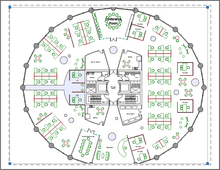
6. Viewport frames exist in paperspace only. Click the single viewport frame to select it. Select the upper-right grip and move it upward and to the right until it is close to the upper-right corner of the paper but inside the plot device limits. Click the lower-left grip, and move it to the lower-left corner inside the device limits (see
Figure 13-15). Press Esc to deselect the viewport.
7. Unfortunately the plan doesn’t fit on the page in 1/16″ scale. Click the PAPER icon on the status bar to switch back into modelspace. Toggle on the Automatically Add Scales to Annotative Objects button in the status bar. Select 1/32″ = 1′-0″ (or 1:300 in metric) from the Viewport Scale menu button on the status bar. The drawing fits on the page, and new annotative objects are created in this scale.
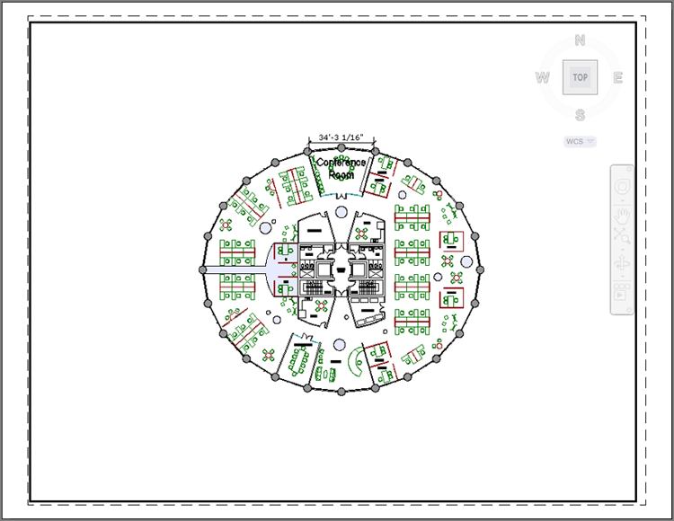
8. Zoom in and select the single dimension object, and move its dimension line upward for clarity. Note, however, that by zooming, you have changed the viewport scale. Again select 1/32″ = 1′-0″ (or 1:300 in metric) from the Viewport Scale menu button on the status bar, and pan the drawing to the center of the page (see
Figure 13-16).
9. Click the MODEL icon on the status bar to switch back to paperspace.
10. Save your work as Ch13-E.dwg or Ch13-E-metric.dwg.
Working on Layout2
In the following steps, you will adjust the viewport on Layout2 and, in the process, discover that certain combinations of building geometry, viewport scales, and paper sizes do not always mesh. You will fix the problem by selecting a different viewport scale, and then adjust the viewport to fit the floor plan. In addition, you’ll create a viewport from scratch and adjust it.
1. If the file is not already open, go to the book’s web page, browse to Chapter 13, get the file Ch13-E.dwg or Ch13-E-metric.dwg, and open it.
2. Click the Quick View Layouts icon on the status bar. Select Layout2, and then press Esc to exit Quick View Layouts mode.
3. As an alternative to clicking PAPER on in the status bar, double-click inside the viewport to activate it. The Paper/Model toggle now indicates that you are in the modelspace of the viewport.
4. Choose 1/4″ = 1′-0″ (or 1:40 in metric) from the Viewport Scale menu on the status bar.
Changing the viewport scale automatically triggers a corresponding change in the annotation scale.
5. Double-click the layout outside of the viewport to switch back into paperspace. Move the cursor across the drawing canvas, and observe that you can move it across the entire paper now that it is active.
6. Viewport frames exist in paperspace only. Click the viewport frame to select it. Select the upper-right grip, and move it upward until it is close to the upper-right corner of the paper but inside the plot device limits. Click the lower-left grip, and move it to the lower-left corner inside the device limits. Press Esc to deselect.
7. Double-click inside the viewport to switch back into modelspace. Drag the mouse wheel (but do not turn the wheel) to pan the drawing over within the viewport to center it on the paper. The 1/4″ (or 1:50 in metric) scale drawing almost fits, but it’s too tight to fit comfortably on ARCH E1 or ISO A0 paper. You couldn’t have known this without first creating the layout and trying to fit the drawing to the paper at this specific scale.
8. Verify that the option Automatically Add Scales To Annotative Objects When The Annotation Scale Changes is toggled on in the status bar, and then select 3/16″ = 1′-0″ scale (or 1:60 in metric) in the Viewport Scale menu. The floor plan now fits the layout.
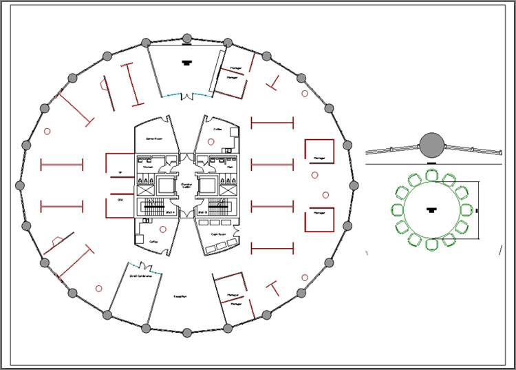
9. Double-click the paper outside the viewport to switch back into paperspace. Select the viewport, and grip-edit it so that it closely surrounds the plan geometry. Move the plan to the left on the paper to make room for another drawing on this layout.
Figure 13-17 shows the result.
10. Type MV (for Make Viewport), and press Enter. Click two arbitrary corner points to the right of the existing viewport to create a new viewport. The MVIEW command ends.
11. Double-click within the new viewport to enter its modelspace. Select 1/2″ = 1′-0″ (or 1:20 in metric) in the Viewport Scale menu on the status bar; the viewports zoom into the Elevator Lobby again. Pan downward until you center the view on the Conference Room. Double-click outside the viewport to return to paperspace.
Figure 13-18 shows the result.
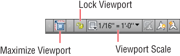
I recommend that you lock viewports immediately after configuring them so that you don’t inadvertently change the drawing scale by zooming.
12. Select both viewport objects, and then click the Lock Viewport icon on the status bar. Press Esc to deselect. Double-click inside the new viewport, and roll the mouse wheel forward to zoom in. Whereas before when you locked the viewport, only the space within the viewport zoomed in, now the entire layout zooms in.
13. Save your work as Ch13-F.dwg or Ch13-F-metric.dwg.
Overriding Layer Properties in Layout Viewports
Each viewport maintains its own set of layer properties that can override the drawing’s basic layer properties. In the following steps, you will use this feature to turn off a selection of layers in a particular viewport, while continuing to display these same layers in another viewport.
1. If the file is not already open, go to the book’s web page, browse to Chapter 13, get the file Ch13-F.dwg or Ch13-F-metric.dwg, and open it.
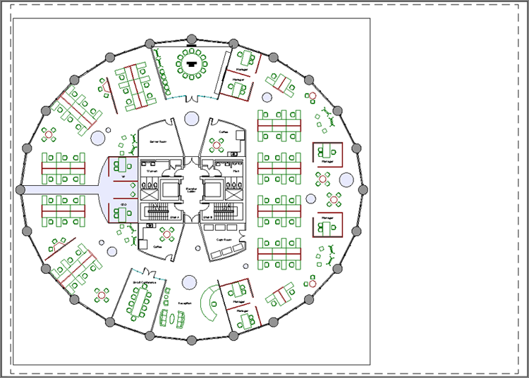
2. Double-click within the larger viewport on Layout2 that shows the entire floor plan to activate it and switch into floating modelspace.
3. Click the Layer Properties tool on the Layers panel on the ribbon’s Home tab.
You can override the color, linetype, lineweight, transparency, and/or plot style layer properties independently in each viewport if so desired.
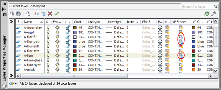
4. Expand the palette to the right by dragging its edge. Observe a set of properties in columns preceded with the letters VP (viewport). Click the icons in the VP Freeze column for layers A-furn, A-flor-fill, and A-flor-patn to freeze them in the current viewport (see
Figure 13-19).
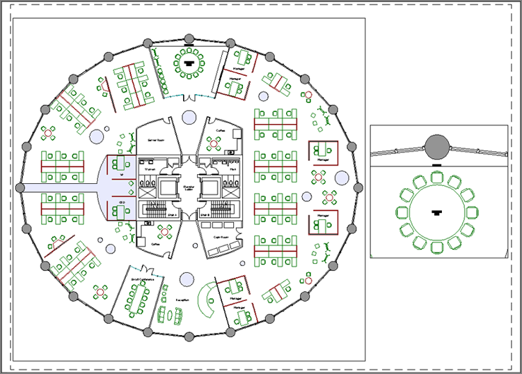
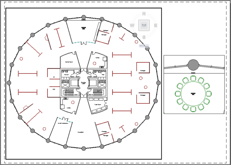
5. Double-click on the paper outside the viewport to switch back into paperspace. The furniture and furniture systems disappear from the current viewport, but the Conference Room round table is still visible in the viewport on the right of Layout2 (see
Figure 13-20). Close the Layer Properties Manager.
6. Save your work as Ch13-G.dwg or Ch13-G-metric.dwg.
Drawing on Layouts
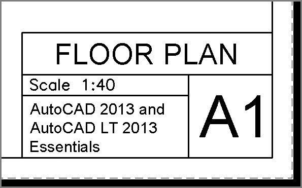
You can draw on layouts just as you can draw in modelspace. However, the types of content drawn on layouts will necessarily be of a different character, such as a title block, viewports, and (optionally) dimensions. Layouts have the measurements of physical sheets of paper and are not meant to hold real-world geometry directly (that is what modelspace is used for).
One way to draw directly on layouts is to use title blocks, which are borders surrounding the drawing that also have rectangles in which text identifying the sheet is placed. You can also draw dimensions directly on layouts. Dimensions added in paperspace are associated with geometry in modelspace. If the real-world geometry changes, then the dimensions will automatically update.
In the following steps, you will draw a title block and add a dimension to the paperspace of the layout:
1. If the file is not already open, go to the book’s web page, browse to Chapter 13, get the file Ch13-G.dwg or Ch13-G-metric.dwg, and open it.
2. Type LA (for Layer Properties Manager), and press Enter. Click the New Layer icon, type Z-Title, and press Enter. Double-click the new layer to make it current. Select a Lineweight value of 0.039″ (or 1.00 mm) for a thick border. Toggle the Plot icon on. Close the Layer Properties Manager.
3. Click the Rectangle tool in the Draw panel. Click the corner points as closely as possible to the edges of the paper in Layout2. You cannot use object snap in this instance.
Title Blocks
Drawings are legal documents and, as such, typically indicate the drawing scale, sheet name, and sheet number. This information is traditionally shown with text or attributes in a title block, which is drawn directly on the layout.
4. Set the Text layer as current by selecting it in the Layer drop-down in the Layers panel.
5. Verify that the PAPER/MODEL toggle on the status bar reads PAPER. Zoom into the smaller viewport on the right of Layout2.
Dimensions added in paperspace are necessarily specific to each drawing and cannot be shown simultaneously in multiple viewports as annotative, modelspace dimensions can.
6. Right-click the Object Snap icon in the status bar, and toggle on quadrant snap. Click the Linear tool in the Annotation panel, and click points A, B, and C as shown in
Figure 13-21. Points A and B are on the quadrants of the circle. A dimension measuring 9′-0″ (274 for metric) appears on the layout in paperspace that looks similar to the dimension you drew earlier in this chapter in modelspace.
7. Click Maximize Viewport on the status bar. A red border indicates that you are working in the modelspace of a viewport in maximized mode.
Working in Multiple Maximized Viewports
When you work in a maximized viewport on a layout that has more than one viewport, the Next and Previous arrows appear surrounding the status bar toggle. Click these arrow icons to cycle through each and every viewport on a layout while staying in maximized mode.
8. Select the circle representing the table, and select its top quadrant grip. Type 4′8″ (140 cm in metric), and press Enter to input the new radius. The circle grows slightly larger.
9. Click Minimize Viewport in the status bar. The drawing canvas returns to Layout2. The dimension in paperspace is automatically updated with the value of 9′-4″ (280 cm in metric).
10. Select the Output tab on the ribbon, and click the Preview tool in the Plot panel. What you now see is what you would get if you published this drawing (see
Figure 13-22). Press Esc to exit the preview.
11. Save your work as Ch13-H.dwg or Ch13-H-metric.dwg. Your drawing should now resemble the files available on the book’s web page.
The Essentials and Beyond
In this chapter, you learned the differences between modelspace and paperspace. You created layouts and viewports, set viewport scales, and adjusted viewports to fit the real-world geometry. In addition, you overrode layer properties in viewports, worked in maximized viewports, drew a title block, and dimensioned in paperspace. In short, you are now fully prepared to create physical and electronic output in the next chapter.
Additional Exercises
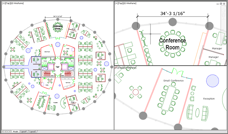
TILEMODE is the system variable that switches between modelspace where tiled viewports are possible (TILEMODE=1) and paperspace where floating viewports are possible (TILEMODE=0). Create tiled modelspace viewports with the VPORTS command on your own. You can alternatively create tiled viewports using the leftmost menu in the upper-left corner of the drawing canvas.
Tiled viewports are most useful when working on 3D models to get multiple simultaneous views of complex geometry, but they can also be used to get a simultaneous overview and detailed view of a 2D drawing. Try working at a few different magnifications in Ch13-H.dwg or Ch13-H-metric.dwg with three viewports so that you can see the overall plan and two detailed views simultaneously.