Chapter 2
Basic Drawing Skills
This chapter teaches you how to draw basic shapes, such as lines, rectangles, circles, arcs, and polygons. You will learn how to correct mistakes, navigate two-dimensional space, and use coordinate systems to draw accurately. In addition, you’ll perform your first editing tasks by joining existing lines in straight, rounded, or angled intersections.
- Navigating 2D drawings
- Drawing lines and rectangles
- Canceling, erasing, and undoing
- Using coordinate systems
- Drawing circles, arcs, and polygons
- Filleting and chamfering lines
Navigating 2D Drawings
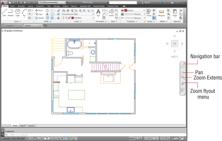
Unlike image-editing programs where zooming in results in blurry, pixilated images, you can zoom in forever in the AutoCAD® program without suffering any loss in quality. However, to avoid getting lost in space, you’ll need to learn how to navigate with a variety of pan and zoom tools that you’ll explore here.
You can change the uniform background color using the
OPTIONS command’s Display tab and Colors button.
2. Click the arrow under the Zoom Extents button on the Navigation bar to open the Zoom flyout menu, and select Zoom In. The Zoom In button replaces the original button (which was Zoom Extents) on the Navigation bar. The last used tool appears on top. Click the Zoom In icon again, and the view is magnified by another factor of 2.
Instead of changing the size of objects, Zoom merely increases the magnification on the canvas.
3. Click Pan in the Navigation bar, drag the mouse from left to right, and then press Enter to end the command.
4. For an alternative method, press and hold the mouse wheel and pan the drawing to center the refrigerator on the canvas (as shown in
Figure 2-2).
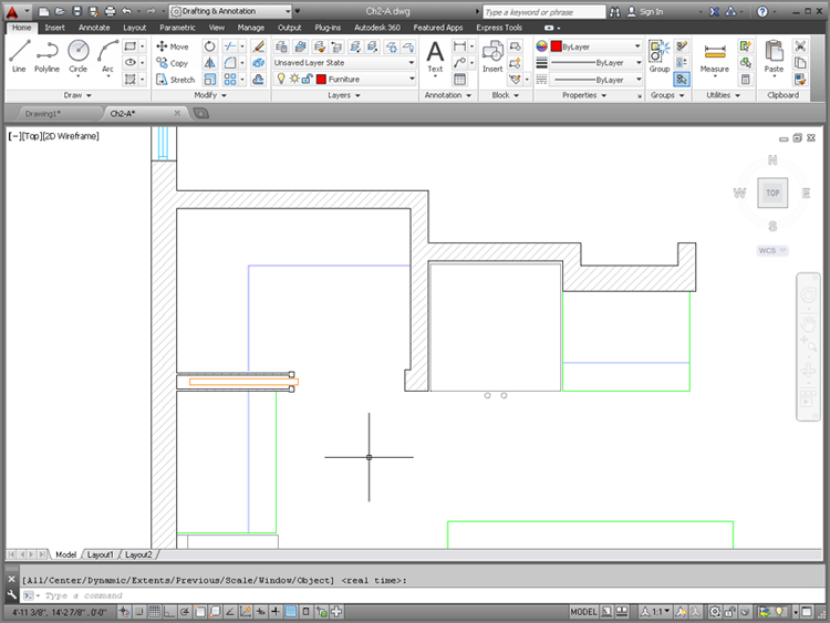
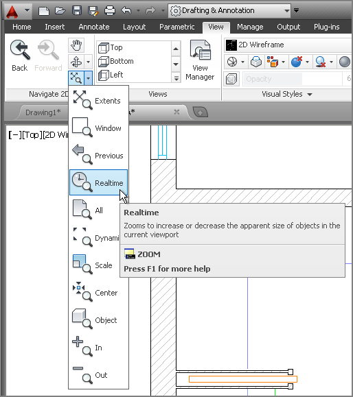
5. Select the Drafting & Annotation workspace if it is not already selected, and then select the View tab in the ribbon. Click the bottom menu arrow in the Navigate 2D panel, and select Zoom Realtime (see
Figure 2-3). Drag up in the document window to zoom in until the refrigerator fills the screen, and then press Esc.
6. Pan to the lower-left corner of the refrigerator using the scroll bars at the edges of the document window. If your scroll bars are not visible, drag the mouse wheel to pan. (You can turn on the scroll bars with the OPTIONS command.)
There are many methods for executing commands in AutoCAD so that you can find your favorite ways of working and become more efficient.
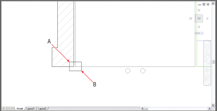
7. Select Zoom Window from the Navigate panel on the View tab. Click points A and B, as shown in
Figure 2-4. The area of the rectangle you draw is magnified to fill the canvas.
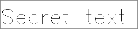
8. Roll the mouse wheel forward to zoom in further, and drag the mouse wheel if necessary to reveal the object in the lower-left corner of the refrigerator (see
Figure 2-5).
It’s not good practice to create infinitesimally small text objects; this was done only to demonstrate the unlimited zoom capability of AutoCAD.
9. Type
Z, and press the spacebar (Z is the command alias for the
ZOOM command). Read the prompt in the Command window or press the down-arrow key to see the menu in the drawing area:
ZOOM
Specify corner of window, enter a scale
factor (nX or nXP), or [All/Center/Dynamic/
Extents/Previous/Scale/Window/Object] <real time>:
You are looking at the roots of AutoCAD in the form of command-line options. This interface was invented before the rest of the GUI, and remarkably it not only still functions but is also a very efficient means of working with AutoCAD. Execute any of the options shown in square brackets by typing the capitalized letter. The option in angled brackets (real time in this case) executes by default if you press Enter without typing anything.
10. Type P, and press Enter to execute Zoom Previous. Press Enter again to repeat the previous command (ZOOM), type P, and press Enter again. Repeat this process until you can see the entire refrigerator again.
11. To see everything that has been drawn, you use Zoom Extents. Double-click the mouse wheel to use Zoom Extents.
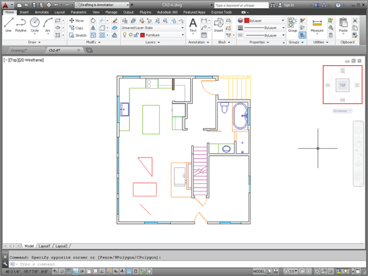
12. Position the cursor over the bathroom sink, and roll the mouse wheel forward to zoom in. Notice that the view stays centered on the sink without having to pan (see
Figure 2-6). Drag the mouse wheel to make slight panning adjustments if necessary to center the target object on the screen.
13. Practice zooming into the kitchen sink, the stove, and the bathtub using the various methods shown in this section. Leave the drawing file open for work in the next section.
Navigation should become second nature to you so you don’t have to think much about it and can focus on drawing.
Drawing Lines and Rectangles
The drawing commands you’ll probably use the most in AutoCAD are LINE and RECTANGLE. You will begin by drawing some lines and rectangles without worrying yet about entering measurements.
Drawing Lines
Lines are the backbone of AutoCAD. Let’s begin drawing lines.
1. In Ch2-A.dwg or Ch2-A-metric.dwg, zoom into the living room at the lower right of the floor plan so that empty space fills the canvas.
You will use some of the status toggles in Chapter 3, “Using Drawing Aids.”
2. Turn off all status toggles in the application status bar. Status toggles are highlighted in blue when they are on and appear in gray when they are off (see
Figure 2-7).
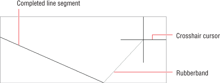
3. Type
L, and press Enter. Click two arbitrary points to define a line object. Observe the flexible segment (called a
rubberband) connecting the cursor with the second point you clicked (see
Figure 2-8).
4. Click another point to draw your second segment. The prompt in the Command window reads:
Specify next point or [Close/Undo]:
Type U, and press Enter. The last point you clicked is undone, but the rubberband continues to be connected to the cursor, indicating that you can keep drawing lines.
5. Click two more points, and then type C and press Enter to create a closing segment between the first and last points. The close option automatically terminates the line command.
6. Press the spacebar (or Enter) to repeat the last command. Click two arbitrary points to create a single line segment. Right-click to open the context menu, and then select Enter with a left-click to complete the Line command.
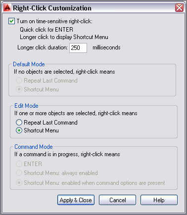
7. Open the Application menu and click the Options button at the bottom. Click the User Preferences tab in the Options dialog box that appears. Under the Windows Standard Behavior section, select Right-Click Customization and then, in the new dialog box, select Turn On Time-Sensitive Right-Click (see
Figure 2-9). Click Apply & Close, and then click OK in the Options dialog box.
Time-Sensitive Right-Click is just that: an option. Try it out to see if you find drawing lines in this way more efficient.
8. Select the Home tab in the ribbon, and click the Line tool in the Draw panel. Click two points, and draw another line. This time, right-click quickly to terminate the Line command.
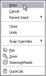
9. Right-click again to repeat the last command, and then click two points on the canvas. Next, slowly right-click (holding down the right mouse button for longer than 250 milliseconds, to be precise), and you’ll see the context menu shown in
Figure 2-10. Left-click on the word Enter from this menu to complete the Line command.
Drawing Rectangles
Line segments are treated as individual objects, whereas the four line segments comprising a rectangle are treated as a single entity. Although rectangles can obviously be drawn with the Line command, specialized commands such as RECTANGLE are more efficient for constructing specific shapes, and they offer more options. Let’s experiment now with this feature.
1. Click the Rectangle tool in the Draw panel, and then click two opposite corner points on the canvas. The command automatically terminates when the rectangle is drawn.
2. Press Enter to repeat the last command. This time pay attention to the prompts in the Command window:
Specify first corner point or
[Chamfer/Elevation/Fillet/Thickness/Width]:
You have the opportunity to use any of the options listed in the square brackets before you even begin drawing the rectangle. However, in this case, you will use the default option, which comes before the word or.
Pay close attention to the prompts in the Command window to see what options are available and what specific input is requested at each step.
3. Click the first corner point in the document window. A new prompt appears:
Specify other corner point or
[Area/Dimensions/Rotation]:
At this point a new command prompt shows another default option before the word or as well as a few options in square brackets. You will again take the default option in this prompt, which is to specify the other corner point.
4. Click the other corner point, and the rectangle is drawn. In addition, the command is automatically terminated.
5. Type
RECTANG (the command alias for the
RECTANGLE command), and press the spacebar. Type
F, and press Enter to execute the Fillet option. The command prompt reads as follows:
Specify fillet radius for rectangles <0.0000>:
6. Type 2″ (or 5 for metric), and press Enter. Units are drawing-specific, so you must use the UNITS command and select Architectural to input feet or inches if you are using a generic or metric template.
Do not type
cm when using metric units; input numbers only.
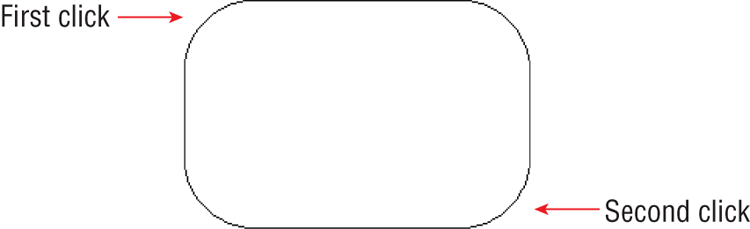
7. Click two points to draw the rectangle. The result has filleted corners (see
Figure 2-11).
8. Draw another rectangle, and observe that it also has rounded corners. Some options such as the fillet radius are sticky; they stay the same until you change them. Zero out the Fillet option by pressing the spacebar, typing F, pressing Enter, typing 0, and pressing Enter again. Click two points to draw a sharp-edged rectangle.
9. Save Ch2-A.dwg or Ch2-A-metric.dwg by clicking the Save button in the Quick Access toolbar.
Drawing Recovery Manager
Occasionally something goes wrong with AutoCAD and it crashes. The next time you launch AutoCAD, the Drawing Recovery Manager will automatically appear, allowing you to recover damaged drawings that were open (and possibly corrupted) when the program unexpectedly came to a halt.
Canceling, Erasing, and Undoing
Making mistakes in AutoCAD is entirely acceptable if you know how to cancel, erase, and/or undo what you’ve done wrong. The following exercise will show you how to do all three:
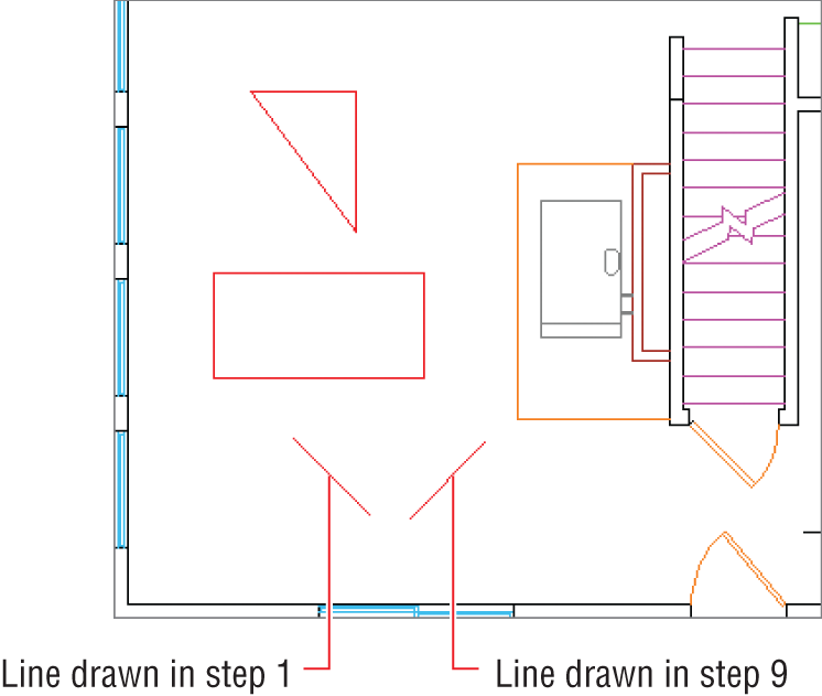
1. Type L, and press Enter. Click two points on the canvas, and then press the Esc key; the LINE command is terminated but the single segment you just created remains. The Esc key will get you out of any running command or dialog box.
2. Type E, and press the spacebar. Click the line created in step 1, and then right-click; the segment is erased.
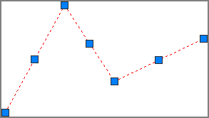
3. Click the Line tool in the Draw panel, click four points on the canvas (making three segments), and then right-click to finish the LINE command.
4. Click each of the segments, one at a time. Blue grips appear on the lines’ endpoints and midpoints (see
Figure 2-12). Grips are used for editing, and you’ll learn more about them in Chapter 4, “Editing Entities.” In the meantime, it’s helpful to know that if you press the Delete key, the lines are gone.
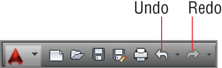
5. Click the Undo arrow on the Quick Access toolbar (see
Figure 2-13). The lines you deleted in step 4 reappear.
6. Click the Redo button, and the lines disappear again.
7. Undo again and, without issuing any command, click two points around the same three lines to create a selection window completely surrounding them. Press the Delete key to erase the selected objects.
The virtually unlimited number of undo and redo actions in AutoCAD means that it is a very forgiving program. However, you can’t undo past the point when you opened an existing file; in other words, undo and redo actions are not stored in the file but in volatile RAM.
8. Click the Undo button’s menu arrow. A list of all the commands you’ve issued in this session appears. Select the bottom item in the list to undo all the way back to the moment when you opened Ch2-A.dwg or Ch2-A-metric.dwg.
Using Coordinate Systems
AutoCAD uses the same Euclidean space you learned about in Geometry class—but don’t panic, I don’t expect you to remember any theorems! You can draw objects in Euclidean space using the following coordinate systems: Cartesian, polar, cylindrical, and spherical. (The last two are rarely used, so they won’t be covered in this book.)
Cartesian coordinates are useful for drawing rectangles with specific length and width measurements. Polar coordinates are used most often for drawing lines with specific lengths and angles, with respect to horizontal. Once you learn coordinate system syntax, you can use the systems interchangeably to draw accurately in any context.
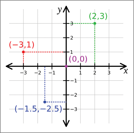
In the Cartesian system, every point is defined by three values, expressed in terms of distances along the x-, y-, and z-axes. In two-dimensional drawings, the z-coordinate value of all objects is 0, so objects are expressed solely in terms of x- and y-coordinates (see Figure 2-14).
Using Absolute Coordinates
Coordinates can be absolute or relative, no matter which coordinate system is used. Let’s first focus on drawing a line using absolute coordinates.
1. If it’s not already open, open Ch2-A.dwg or Ch2-A-metric.dwg.
2. Click the Line tool on the Draw panel. The prompt in the Command window reads:
Specify first point:
Type 0,0 and press Enter. The origin point of Euclidean space has coordinates 0 in x and 0 in y, which is written as 0,0.
3. Now the prompt in the Command window reads:
Specify next point or [Undo]:
Type 3′,0 (or 90,0 in metric), and press Enter. Right-click to finish the LINE command. You drew a line measuring 3′ (or 90 for metric) horizontally along the x-axis.
Using Relative Coordinates
Calculating where every object is in relation to the origin point (which is what absolute coordinates require) would be far too cumbersome in practice. Therefore, relative coordinates are used more frequently. Let’s explore how to use them:


1. Click the Line tool on the Draw panel. Click an arbitrary point in the middle of the living room. The coordinates of the point you clicked are unknown; thankfully, you won’t ever need to find out what they are.
2. Type @3′,0 (or @90,0 in metric), and press Enter twice. Another 3′ (or 90 for metric) line has now been drawn horizontally. The @ symbol tells AutoCAD to consider the previous point as the origin point, relatively speaking.
3. Press Enter to repeat the last command. You’ll see this prompt:
Specify first point:
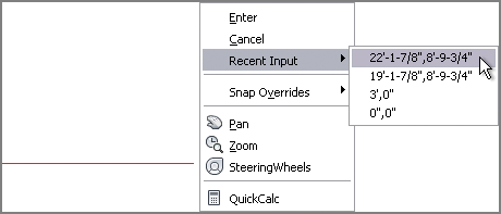
4. Right-click in the drawing canvas, and hold (for longer than 250 milliseconds) to open the context menu. Select the first coordinate value from the Recent Input menu (see
Figure 2-15). You will use the last point entered as the first point in a new line. A rubberband connects the right end of the horizontal line to the cursor.
5. Type @0,6′ (or @0,180 in metric), and press Enter. A line measuring 6′ (or 1.8m) is drawn vertically along the y-axis.
6. Type @-3′,0 (or @-90,0 in metric), and press Enter. Type @0,-6′ (or @0,-180 in metric), and press Enter twice to complete a rectangle.
7. Click the Erase tool on the Modify panel (of the Home tab); select all four lines you just drew and right-click.
8. It’s very efficient to use
RECTANGLE with Cartesian coordinates. Click the Rectangle tool on the Draw panel, and then click an arbitrary point at the bottom of the living room. The prompt reads:
Specify other corner point or [Area/Dimensions/Rotation]:
9. Type @3′,6′ (or @90,180 in metric), and press Enter. The same rectangle that you more laboriously drew with lines is already done.
Using Polar Coordinates
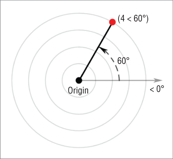
Polar coordinates are another useful way of measuring Euclidean space. In polar coordinates, points are located using two measurements: the distance from the origin point and the angle from zero degrees (see Figure 2-16). East is the default direction of zero degrees.
By default, zero degrees is toward the East, or right side of the canvas. In addition, positive angles are typically measured counterclockwise from East. These defaults can be set in the
UNITS command.
Let’s explore how to use polar coordinates:
1. Click the Line tool on the Draw panel. Click an arbitrary first point in the living room, and then type @3′<45 (or @90<45 in metric) and press Enter to end the LINE command. You have drawn another 3′ (or 90 for metric) line using relative polar coordinates.
The less than symbol (hold Shift and press the comma key) represents angular measure in AutoCAD. Think of the < symbol as the representation of an angle.
2. Press Enter to repeat the last command. Click an arbitrary first point, move the cursor up and to the left, type 3′ (or 90 for metric), and press Enter twice. A 3′ (or 90 for metric) line is drawn at an arbitrary angle.
Specifying Angles with the Cursor
Direct distance entry is the relative method of using the cursor to determine an angle, rather than typing in a specific number of degrees following the < symbol. Direct distance entry is most efficiently used with Ortho and/or Polar modes, which you’ll learn about in Chapter 3.
3. Press L, and then press the spacebar. Click an arbitrary first point, type @4′<180 (or @120<180 in metric), and press Enter. The line is drawn to the left from the first point because 180 degrees is the same direction as angle zero but leads in the opposite direction.
4. Type @3′<–90 (or @90<-90 in metric), and press Enter. Negative angles are measured clockwise from angle zero by default. Press C and then Enter to close the 3:4:5 triangle you’ve just drawn.
5. Type
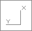
UCSICON, and press Enter.
UCS stands for
user coordinate system. You, the user, can change the coordinate system’s orientation. Type
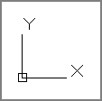
on, and press Enter. An icon indicating the directions of the positive x- and y-axes is displayed in the lower-left corner of the canvas (see
Figure 2-17).
AutoCAD LT® has only one coordinate system that cannot be changed. AutoCAD LT users can skip ahead to the next section.
6. Type
UCS, and press Enter. The prompt in the Command window reads as follows:
Specify origin of UCS or [Face/NAmed/Object/
Previous/View/World/X/Y/Z/ZAxis] <World>:
There is much you can do with the UCS, but here you will simply rotate the UCS about its z-axis (the axis coming out of the screen). Type Z, and press Enter.
7. Type
90, and press Enter to rotate the coordinate system. Observe that the UCS icon has changed to reflect the new orientation (see
Figure 2-18).
8. Type
PLAN, and press Enter. The prompt in the Command window reads:
Enter an option [Current ucs/Ucs/World] <Current>:
The option in the angled brackets,
<Current>, is what you want, so press Enter to make this selection. The house is reoriented with respect to the current UCS (see
Figure 2-19). Notice that the ViewCube’s compass directions are rotated (North is now to the right).
Rotating the Plan to Match the UCS
User coordinate systems are usually associated with 3D modeling, but there is one transformation especially useful for 2D drafting: rotation about the z-axis. If you are drawing a building wing or mechanical part that is at an angle with respect to horizontal (especially when the angle isn’t an increment of 90 degrees), try rotating the UCS’s z-axis and then use the PLAN command to reorient the drawing to the new horizontal.
9. Click the Line tool on the Draw panel. Click an arbitrary first point in the living room, and then type
@3′<45 (or
@90<45 in metric), and press Enter to end the
LINE command. You have drawn another 3′ (or 90 for metric) line using relative polar coordinates (the same as step 1). However, this time the new line has a different orientation with respect to the original line and the rest of the house (see
Figure 2-20).
10. To restore the current coordinate system to its original state, called the world coordinate system (WCS), type UCS and press Enter twice. Then type PLAN, and press Enter twice more. The plan is oriented to the WCS as it was initially. Observe that North is up again in the ViewCube.
Drawing Circles, Arcs, and Polygons
Arcs are sections of circles. Polygons are regular figures made of straight segments such as a triangle, square, pentagon, or hexagon. A polygon with a large number of segments may look like a circle but is fundamentally different.
There are many options for creating circles, arcs, and polygons. AutoCAD provides these options to make it easier to create accurate shapes based on all the types of geometric situations that typically arise in drawings.
Creating Circles
Let’s draw some circles on the kitchen stove to represent the burners:
1. Zoom into the stove in the kitchen. Two of the burner circles are missing, and you will draw them.
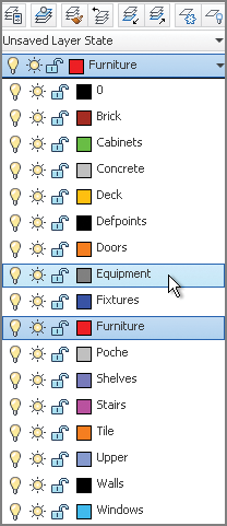
2. On the Home tab, take a look at the Layer drop-down menu in the Layers panel, and observe that Furniture is the current layer (because you see its name without having to open the drop-down). Open the Layer drop-down menu, and select Equipment as the current layer (see
Figure 2-21).
Drawn objects appear on whichever layer is current. Think of layers as invisible sheets of tracing paper that you draw on. You’ll learn more about layers in Chapter 6, “Controlling Object Visibility and Appearance.”
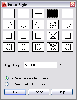
3. You will use preexisting points as guides in drawing the burners. However, the points are difficult to see right now because they are represented as single pixels. Expand the Utilities panel on the Home tab, and select Point Style. In the Point Style dialog box, select the X icon and click OK (see
Figure 2-22).
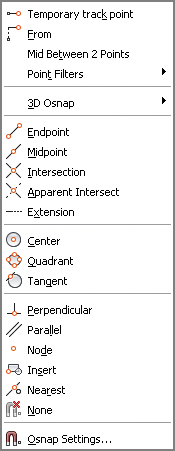
4. Click the Circle tool on the Draw panel. Before you click a center point, hold down Shift and right-click to open the Object Snap context menu (see
Figure 2-23).
Drawing objects close by eye is not good enough in AutoCAD. Always use object snaps to connect objects precisely.
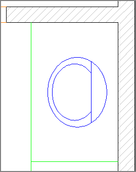
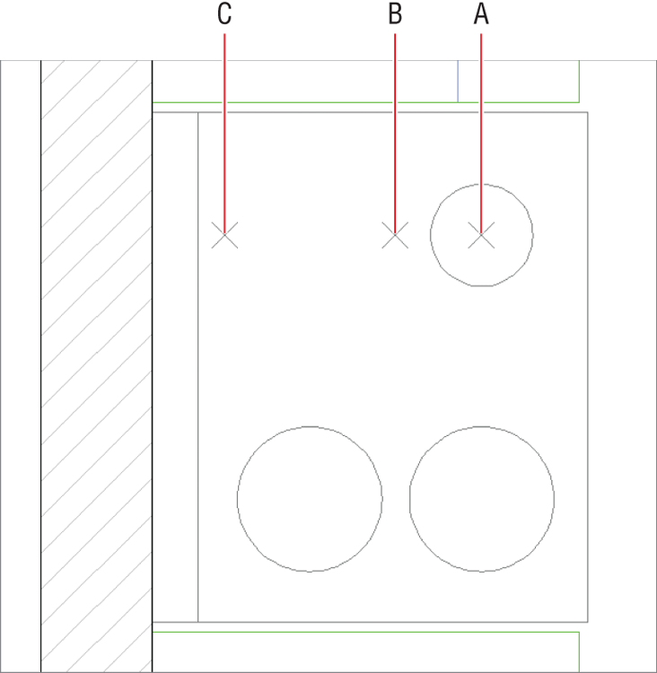
5. Select Node from the context menu, and then click point A, as shown in
Figure 2-24. The prompt in the Command window reads:
Specify radius of circle or [Diameter] <0′-0″>:
Type 3″ (or 8 in metric), and press Enter to create a circle with a radius of 3″ (or 8 for metric). Note that typing the inch symbol is not necessary. Never type m, cm, or mm to represent metric units.
6. Right-click to repeat the last command. The prompt in the Command window reads:
Specify center point for circle or
[3P/2P/Ttr (tan tan radius)]:
Type
2P to indicate the two-point option, and press Enter. Hold down Shift, and right-click to open the Object Snap context menu. Select Node, and then click point B, as shown in
Figure 2-24.
Object snaps listed in the context menu must be selected each time they are used. You will learn how to set up running object snaps in Chapter 3.
7. Hold Shift again, right-click, and choose Node. Click point C, as shown in
Figure 2-24, and the
CIRCLE command is completed.
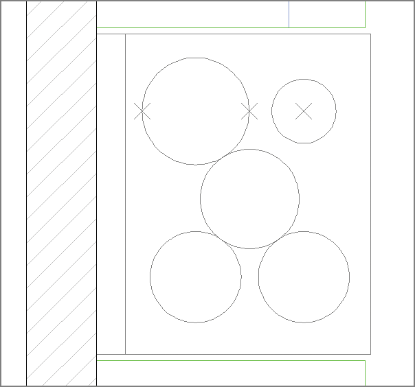
8. Click the arrow under the Circle tool in the Draw panel, and select 3-Point. Shift+right-click, and select Tangent. Click the circle you drew in the previous step.
9. Hold Shift, right-click again, and type
G. Notice that this letter is underlined in the word Tangent in the context menu (refer to
Figure 2-23). Click the circle on the bottom left.
10. Type
TAN, press Enter to invoke the Tangent object snap, and click the circle on the lower right. You can type the first three letters of any object snap as an alternative to using the context menu. AutoCAD draws a circle precisely tangent to the three others (see
Figure 2-25).
11. Erase the three-point objects and the last circle you drew to leave the four burners of the stove.
Creating Arcs
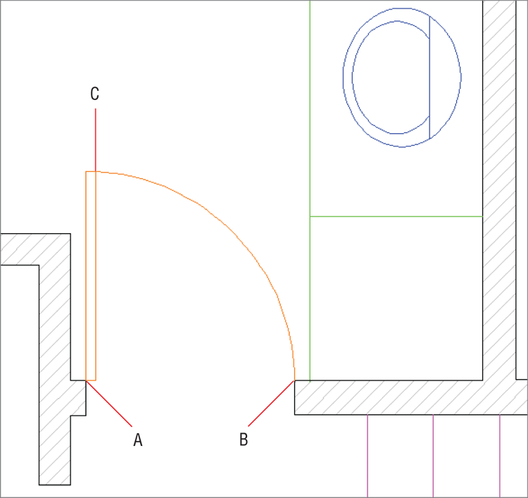
Arcs have more options than circles because of the complexities of the geometric situations in which arcs can be drawn. In the next set of steps, you will use one such arc option to draw a door swing:
1. Zoom into the bathroom. The bathroom door needs an arc to represent the way it swings.
2. Select Doors from the Layer drop-down menu in the Layers panel.
3. Click the Arc tool’s drop-down flyout menu in the Draw panel, which is indicated by the arrow under the word Arc. Select Center, Start, End. This is the sequence in which information must be entered.
4. Type
INT, press Enter to invoke the Intersection object snap, and click the center point A shown in
Figure 2-26.
5. Hold Shift and right-click. Select Endpoint from the context menu, and click the start point B (shown in
Figure 2-26).
6. Hold Shift and right-click, type
END, and click the arc endpoint C (shown in
Figure 2-26). The arc appears, and the command is completed.
Controlling Arc and Circle Smoothness
Arcs and circles are defined with perfect curvature in AutoCAD, but sometimes they appear blocky on screen. The system variable VIEWRES controls how smoothly arcs and circles are drawn on screen. Adjust this on the View tab under the Visual Style panel’s expansion menu. Set the resolution to the maximum VIEWRES value by typing VIEWRES, pressing Enter twice, typing 20000, and pressing Enter again. Type REGEN, and press Enter to make this change take effect on screen.
Drawing Polygons
When you want to draw triangles, squares, pentagons, or any figure having equally sized edges, use the POLYGON command. You can draw these shapes inside or outside a circle, or specify the edge length, as shown in the following steps:
1. Select the Home tab if it’s not already active. Make the Furniture layer current by selecting it from the Layer drop-down menu in the Layers panel.
2. Zoom into the living room.
3. Click the Rectangle tool’s drop-down flyout, and select the Polygon tool. The prompt in the Command window reads:
Enter number of sides <5>:
4. Type 4, and press Enter to draw a square.
5. The command prompt now reads:
Specify center of polygon or [Edge]:
Type E, and press Enter to specify an edge length and direction. Click a point somewhere in the living room as the first endpoint of the edge, and type @2′<0 (or @60<0 in metric) to specify the second endpoint of the edge relative to the first one, using polar coordinates in this case. A 2′ (or 60 for metric) square appears.
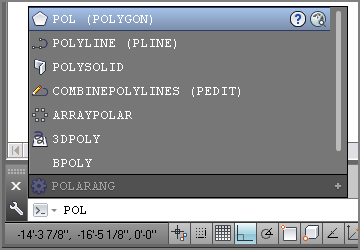
6. Type
POL, and observe that, as you type, the AutoComplete menu appears above the command line suggesting commands and system variables (see
Figure 2-27). Press the down-arrow key until POLYGON is highlighted, and then press Enter.
AutoComplete has been enhanced in AutoCAD 2014 with mid-string search functionality so you see all terms containing the string of letters you type.
7. Type
6, and press Enter to draw a hexagon. Click a point in the living room where you want to center the hexagon. The prompt now reads:
Enter an option [Inscribed in circle/
Circumscribed about circle] <I>:
8. Press Enter to accept the default Inscribed In Circle option.
9. Type 1′ (or 30 in metric) as the radius of the circle and press Enter. A hexagon fitting inside a 1′ (or 30 for metric) radius circle appears.
Filleting and Chamfering Lines
Fillet and Chamfer are tools that create transitions between objects. Fillet creates arcs and Chamfer creates lines. Fillet is most commonly used for a purpose for which it probably wasn’t designed—joining separate lines so that they intersect at their endpoints, without creating arcs at all.
Joining Nonparallel Lines
Fillet and Chamfer can be used to join lines that are crossing as well as lines that don’t meet. Chamfer doesn’t work on parallel lines at all, but Fillet will create a half circle connecting the endpoints of parallel lines, regardless of the fillet radius. Let’s explore the FILLET and CHAMFER commands:
1. Draw two lines. It doesn’t matter what size they are or what angle is between them, as long as the lines aren’t parallel.
2. Press the F12 key to toggle dynamic input on, an optional mode that displays command-line options on the canvas. Position the cursor on the canvas, and type CHA, the command alias for the CHAMFER command, and the AutoComplete window appears on the canvas rather than in the Command window.
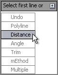
3. Press Enter, and then press the down-arrow key to expand the command’s options on screen.
4. Press the down-arrow key three more times, and press Enter to select the Distance option in the Dynamic Input display (see
Figure 2-28). Type
1′ (or
30 for metric), and press Enter twice to input equal first and second distances which are 1′ (or 30 for metric) each.
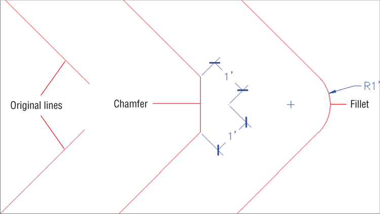
5. Click one line and then hover the cursor over the second line; you’ll see a preview of the chamfer that will be created. Click the second line to perform the chamfer and complete the command. (The chamfer is shown in the middle of
Figure 2-29.)
Fillet and chamfer previewing works only if When A Command Is Active is selected on the Selection tab of the Options dialog box. This option should be selected by default.
6. Draw two more noncrossing and nonparallel lines.
7. Type F, and press Enter to execute the FILLET command. Press the down-arrow key, and choose Radius from the Dynamic Input display. Type 1′ (or 30 for metric), and press Enter.
Fillet radius and chamfer distances are sticky; they stay the same until you change them.
8. Click the first line, and then hover the cursor over the second line; the fillet preview shows on screen. Click the second line to commit to that particular radius. (This fillet is shown at the right of
Figure 2-29.)
Joining Crossed Lines
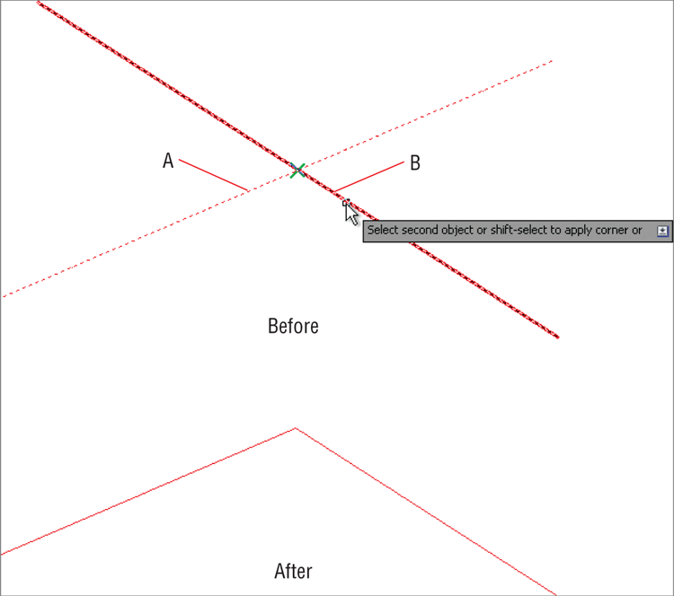
When lines cross, there are multiple fillet and chamfer possibilities on different sides of the intersection. In the case of crossing lines, you must select the lines on the portions that you want to keep, as shown in these steps:
1. Draw two lines that cross.
2. Type F, and press Enter. Press the down arrow to access the Dynamic Input display, and select Radius. Type 0, and press Enter. Now Fillet will not create an arc at all.
3. Click the points A and B, as shown in
Figure 2-30. The lines are joined at their endpoints, and the remaining portions of the lines beyond their intersection point are trimmed away.
In AutoCAD 2014 you can fillet polyline segments, creating closed polylines automatically (even with a zero radius).
4. Click the Save As button on the Quick Access toolbar. Type
Ch2-B.dwg or
Ch2-B-metric.dwg as the filename. The end file is provided on Chapter 2’s download page at
www.sybex.com/go/autocad2014essentials for your convenience.
The Essentials and Beyond
This chapter covered the mechanics of drawing many basic object types, including lines, circles, arcs, and polygons. You learned how to navigate 2D drawings in a variety of ways. By learning how to cancel, erase, and undo, you won’t be afraid to make mistakes in AutoCAD. In addition, you explored how coordinate systems make accurate drawing possible. Finally, you altered existing lines with Fillet and Chamfer, and learned how to join lines by using a zero fillet radius.
Additional Exercise
- Explore the Donut and Solid tools on your own. Unlike most AutoCAD drawing tools, these older commands produce objects that have two-dimensional solidity. Refer to Help in AutoCAD if you need further information.