Chapter 4
Editing Entities
Drawing in the AutoCAD® program is not just about creating lines, rectangles, circles, and other shapes. Most of your time will be spent editing entities. Although AutoCAD provides the basic tools for transforming shapes, such as Move, Copy, Rotate, and Scale, more complex editing tools are also available, such as Array, Trim, Extend, Lengthen, Stretch, Offset, Mirror, Break, Join, and Overkill.
- Creating selection sets
- Move and Copy
- Rotate and Scale
- Working with arrays
- Trim and Extend
- Lengthen and Stretch
- Offset and Mirror
- Grip editing
Creating Selection Sets
All editing commands operate on one or more drawing entities. In complex drawings you have to plan how you will select only those entities you want to edit while leaving all other entities unaffected. You will learn a number of techniques for adding and removing entities from the selection set, which is the collection of entities your chosen editing command acts upon.
Creating a Selection Set at the Select Objects: Prompt
To edit objects, you must first select them. In complex drawings, selecting would be tedious if you had to click one object at a time. In the following steps, you will learn several efficient selection methods that you can use at any Select objects: prompt, which appears in every editing command.
A white background works well in a book, but AutoCAD has a dark background by default. You can change the background color on the Display tab of the
OPTIONS command.
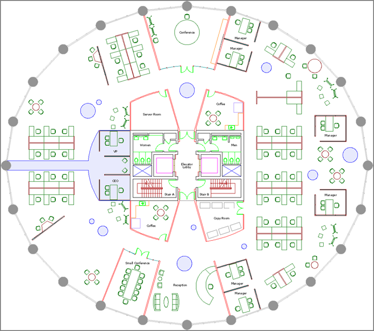
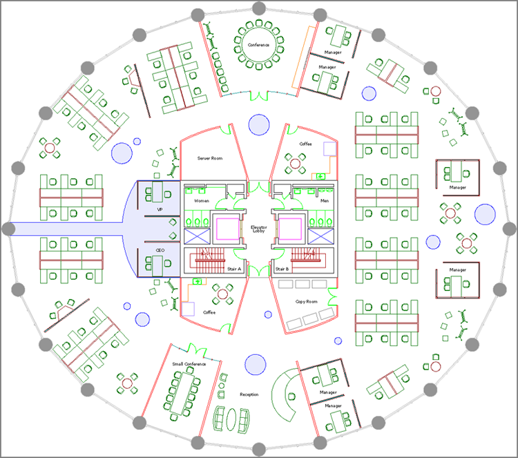
2. Zoom into Stair A in the building core.
3. Click the Erase tool in the Modify panel on the Home tab of the ribbon. The prompt in the Command window reads as follows:
Select objects:
This is the same way almost every command begins—with the opportunity to create a selection set.
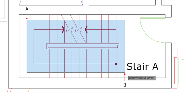
4. Click point A and then B, as shown in
Figure 4-2. Observe that a transparent
implied window appears between these points. The objects that are selected are only those completely contained within the borders of the blue window. This particular selection includes the stair arrows, handrails, and three lines representing stair treads near the break lines.
You can draw implied windows either by clicking two opposite corner points, or by clicking the first corner point and then dragging to the opposite corner and releasing the mouse button.
5. Type
R (for Remove), and press Enter. The command prompt reads as follows:
Remove objects:
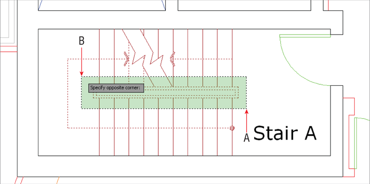
6. Click point A and then B, as shown in
Figure 4-3. When you click the first point on the right (A) and move the cursor to the left (at B), a transparent green
crossing window appears between the points. Whatever the green window crosses is selected. The crossing selection removes the handrail and two of the stair treads because the selection was made at the
Remove objects: prompt.
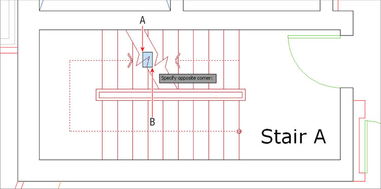
7. Click point A and then B, as shown in
Figure 4-4. This implied window selects the short line segment trapped in the break line and removes it from the selection set.
8. Type
A (for Add), and press Enter. The command prompt again reads as follows:
Select objects:
9. Click each of the break lines to add them to the selection set. All of the break line segments are selected in two clicks because the break lines are polylines.
10. Hold Shift, and click the break lines again. They are removed from the selection set without being at the Remove objects: prompt.
11. Press Esc to cancel the ERASE command.
Creating a Selection Set Before Deciding on a Command
In addition to creating a selection set at any Select objects: prompt, you can create a selection set first and then decide which command to use afterward. (Additional dynamic input prompts are available on screen when you select objects first.) Let’s explore these additional selection methods:
1. If the file is not already open from performing the previous step, go to the book’s web page, browse to Chapter 4, download the file Ch4-A.dwg (or Ch4-A-metric.dwg), and open it.
2. Toggle on Dynamic Input mode in the status bar.
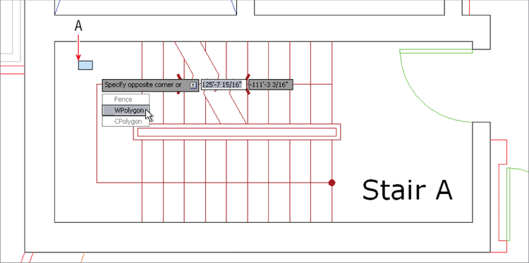
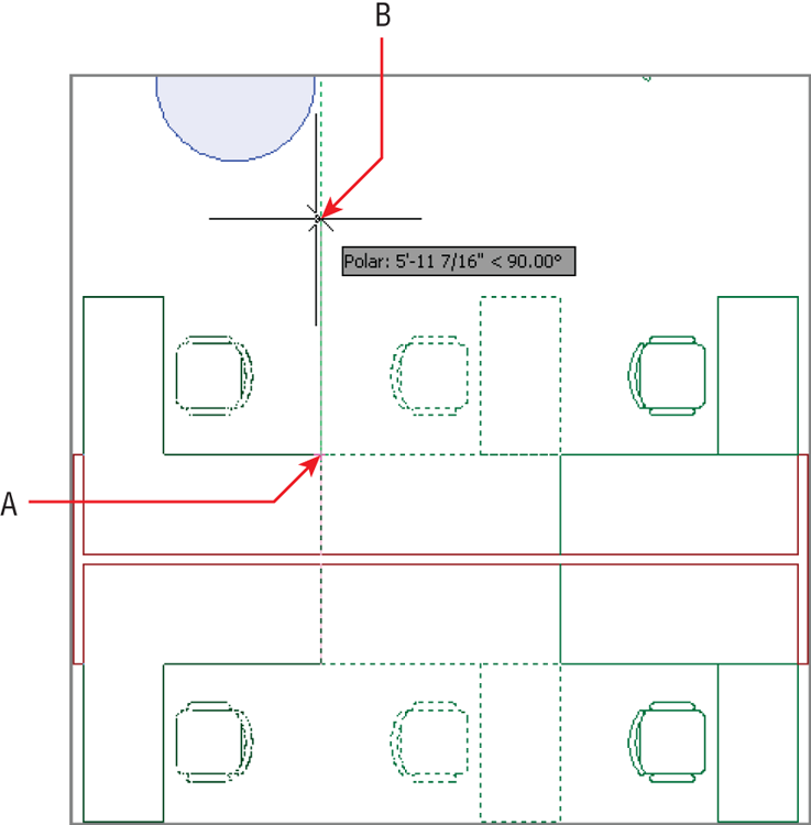
3. Click point A, as shown in
Figure 4-5. Press the down-arrow key to expand the dynamic input menu on screen. Select WPolygon.
The related CPolygon option creates a polygonal crossing window, shown in transparent green. The Fence option allows you to draw a multisegmented line that selects whatever it crosses.
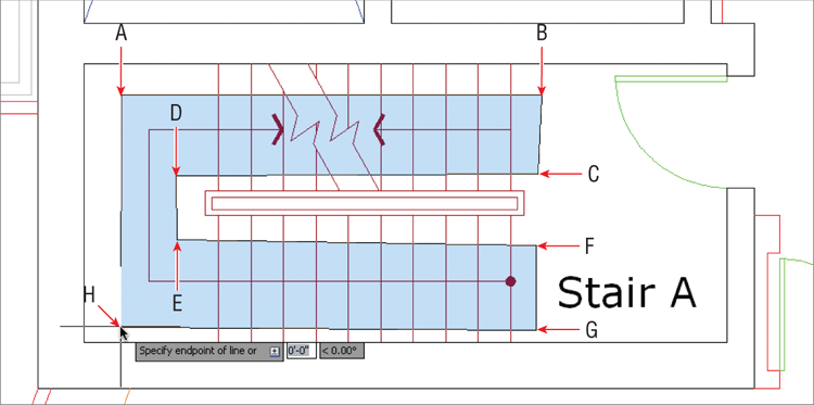
4. Click points B through H, as shown in
Figure 4-6. The transparent blue polygon you are drawing functions the same as an implied rectangular window; the difference is the polygonal window offers more flexibility because you can shape it. Only those objects completely contained within the borders of the blue window will be selected.
5. Press Enter to make the selection. Square blue dots appear on the selected objects—these are called grips, and you will learn to use them later in this chapter. Press Esc to deselect.
6. Toggle on Ortho mode in the status bar. Without being concerned with measurements or accuracy, draw a line under the word Stair, a circle around the letter A, and a rectangle around the entire section, in that order (see
Figure 4-7).
7. Type SELECT, and press Enter. Select the circle and the line and press Enter. The SELECT command is used merely to make a selection. The grips for the circle and line appear; press Esc to deselect.
8. Click the Erase icon on the Modify panel. At the Select objects: prompt, type P (for Previous) and press Enter. The circle and line are selected because they comprise the set of objects that was selected previously. Press Enter again to delete these objects.
You can select the entire drawing by typing
all at any
Select objects: prompt.
9. Press the spacebar to repeat the last command (ERASE). Type L (for Last), and press Enter. The rectangle is selected because it was the last object you created. There can only be one last object. Press Enter again to delete the rectangle.
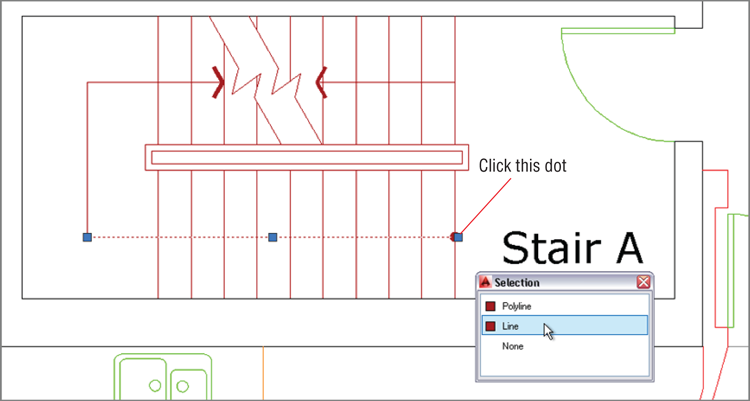
10. Toggle on Selection Cycling in the status bar.
11. Click the dot at the end of the stair direction line (shown in
Figure 4-8). This dot is at the confluence of the horizontal stair direction line and the vertical tread line. When Selection Cycling is on, you are presented with the Selection dialog box whenever your selection is ambiguous. Hover the cursor over the items in the list and each one’s grips are highlighted on the drawing canvas. Select the line in the list that highlights grips on the stair direction line as shown in
Figure 4-8 and then press Esc.
12. Press Ctrl+W to toggle selection cycling off.
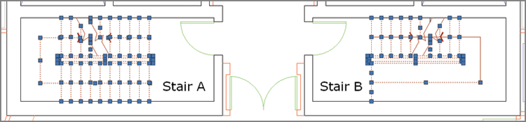
13. Select one of the vertical tread lines in Stair A by clicking on it. Right-click, and choose Select Similar from the context menu that appears. All lines on the same layer are selected; you might have to zoom out to see both stairs (see
Figure 4-9). Other object types on the same layer remain unselected because they were not similar enough. Press Esc.
Selecting Similar Objects
Type SELECTSIMILAR, press Enter, type SE, and press Enter again to open this command’s Settings dialog box. Here you can choose criteria to determine which object properties must match in order to be selected by this useful command: Color, Layer, Linetype, Linetype scale, Lineweight, Plot style, Object style, or Name.
Move and Copy
MOVE and COPY are the most commonly used commands in AutoCAD. As you’ll see in the following steps, they are very similar in that they both require a distance and a direction to indicate where you plan to displace the selected objects.
1. If the file is not already open from performing the previous step, go to the book’s web page, browse to Chapter 4, download the file Ch4-A.dwg (or Ch4-A-metric.dwg), and open it.
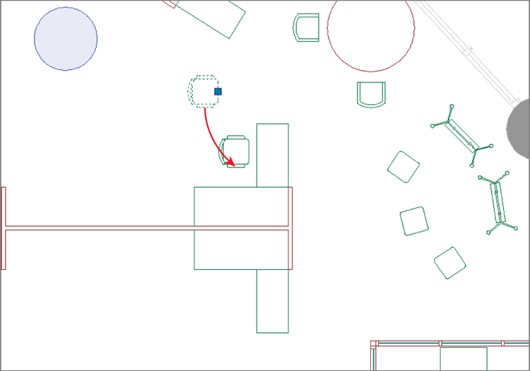
2. Pan to the upper-right quadrant of the building, and zoom into the furniture grouping that needs to be filled in.
3. Click the chair that is not in front of a desk to select it. Position the cursor over the selected chair, but not over its grip. Drag the chair to move it closer to the upper desk, as shown in
Figure 4-10.
The disadvantage to moving by dragging is that the displacement is unmeasured, and you can’t use Object Snap to maintain accuracy.
4. To position the chair more precisely, click the Move tool in the Modify panel. Select the chair you just moved in the previous step and press Enter. The command prompt reads as follows:
Specify base point or [Displacement] <Displacement>:
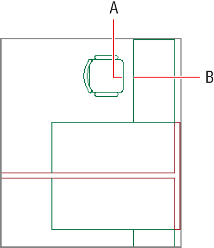
5. Right-click the Object Snap toggle in the status bar, and choose Midpoint from the context menu if it is not already selected. Click the base point at the midpoint of the front of the chair (point A in
Figure 4-11).
6. Click the second point, (B in
Figure 4-11). The chair is moved precisely to the midpoint of the desk edge.
7. Press the spacebar to repeat MOVE. Type P, and press Enter twice to select the same chair again. Press Enter once more to accept the default option <Displacement>. In Displacement mode, the first point is the origin point. Any coordinates you enter are relative to the origin, so typing the @ symbol is unnecessary. Type 4<180 (or 10<180 in metric) and press Enter.
8. Click the Copy tool in the Modify panel. Select the chair you just moved and press Enter. Select the midpoint of the desk (point B in
Figure 4-11) as the base point, and then click the midpoint of the corresponding mirror image desk below in the same furniture group as the second point. Press Enter to end the
COPY command.
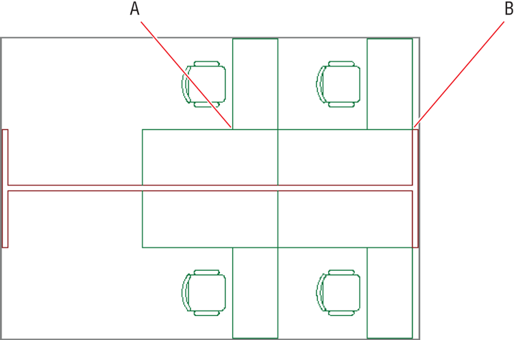
9. Press the spacebar to repeat the previous command, select both desks and chairs with crossing windows, and press Enter. Select point A in
Figure 4-12 as the base point and point B as the second point. Press Esc to end the command.
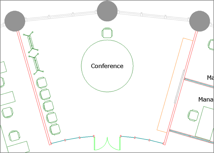
10. Pan over to the Conference room. To copy an array of chairs along the left wall, you will rotate the user coordinate system (UCS) to match the orientation of the wall. Type
UCS, and press Enter. Select the Object option by typing
OB and press Enter. Select the inner left wall line and watch as the crosshair cursor changes to match the angle of the wall (see
Figure 4-13).
11. Type CO (for Copy), and press Enter. Select the chair that is against the left wall of the Conference room and press Enter. Click an arbitrary base point by clicking in the empty space of the Conference room. Toggle on Polar Tracking on the status bar if it is not already on.
12. Move the cursor down along the direction of the wall, type
A (for Array), and press Enter. The command prompt reads as follows:
Enter number of items to array:
Type
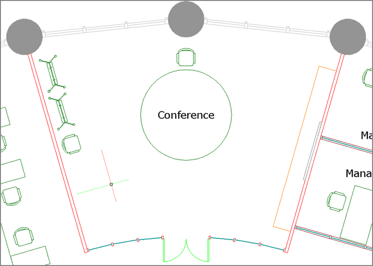
5, and press Enter. Type
F (for Fit), and press Enter. Move the cursor downward, and observe that five ghosted chairs appear. When the spacing looks right, click in the document window to complete the array and press Enter.
Figure 4-14 shows the result.
13. Type UCS, and press Enter twice to accept the default option of World. The crosshair cursor returns to its default orientation.
14. Save your work as Ch4-B.dwg (or Ch4-B-metric.dwg).
Rotate and Scale
The ROTATE and SCALE commands are obviously essential to drawing; each requires a base point to indicate the center from which objects are transformed. Numerically speaking, you typically rotate by degrees or scale by percentages about base points. On the other hand, you can avoid using numbers entirely by choosing the Reference options, which let you rotate or scale selection sets in relation to other objects. Let’s rotate and scale objects.
1. If the file is not already open from performing the previous step, go to the book’s web page, browse to Chapter 4, download the file Ch4-B.dwg (or Ch4-B-metric.dwg), and open it.
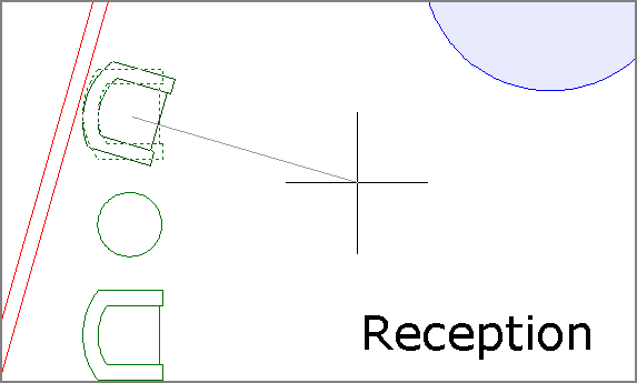
2. Navigate to Reception at the bottom of the floor plan. Click the Rotate button in the Modify panel, select the upper chair, and press Enter. The command line reads as follows:
Specify base point:
Click a point in the center of the chair; you don’t need to snap this point because an approximation is good enough at this point.
3. Toggle off Polar Tracking (and Ortho if it is on) in the status bar. Move the cursor around the point, and observe that a rubberband line connects the base point to your cursor and a ghosted image of the chair is superimposed over the original chair representation. Move the cursor until the rubberband aligns more or less perpendicularly to the wall behind the chair (see
Figure 4-15) and click.
4. Click the chair that you just rotated to select it without issuing an explicit command. Hold the Ctrl key, and repeatedly press the arrow keys to nudge the selected object a few pixels at a time. Nudge the chair so that it is a similar distance from the wall and the round table as compared to the other armchair in Reception. Press Esc to deselect all.
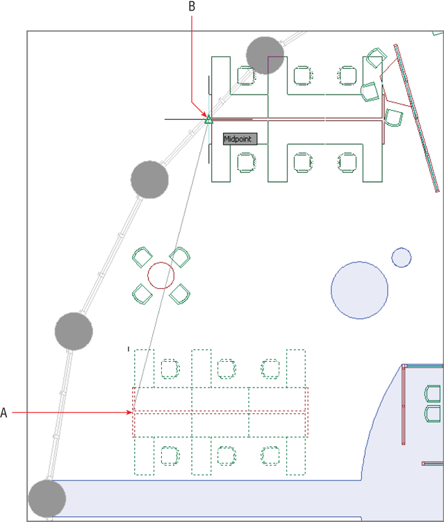
5. Zoom out and focus on the upper-left quadrant of the building. Type
CO (for Copy), and press Enter. Select the furniture group shown in
Figure 4-16, and press Enter. Select midpoint A as the base point, and select midpoint B as the second point. Press Esc to end the command.
6. Type
RO (for Rotate), and press Enter. Select the furniture group you just copied and press Enter. Select the same midpoint where the furniture group was attached to the midpoint of the shell window wall as the base point of the rotation. The command line reads as follows:
Specify rotation angle or [Copy Reference] <0.00>:
Type R (for Reference), and press Enter. Instead of specifying the reference angle with a number, you will determine the angle interactively. Type @ and press Enter to input the base point of the rotation as the base point of the reference angle.
7. Click endpoints A and B as shown in
Figure 4-17 to specify the second point of the reference angle and the new angle. The furniture group rotates so that it is parallel and centered on the window wall.
Using the
ROTATE and
SCALE commands’ Reference options allows you to transform with reference to other objects without having to input numerical angles or scale factors.
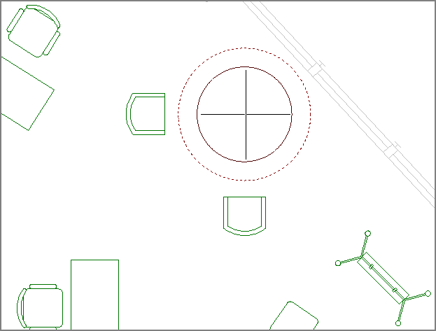
8. Pan over to the upper-right quadrant of the building, and zoom in on the oversized round table. Click the Scale icon on the Modify panel, select the circle representing the table, and press Enter. The command line reads as follows:
Specify base point:
Snap to the center of the circle. Type
.5, and press Enter to scale the circle down to 50 percent of its original size (see
Figure 4-18).
9. Toggle on Polar Tracking on the status bar, and move the chairs closer to the table, both horizontally and vertically.
10. Save your work as Ch4-C.dwg (or Ch4-C-metric.dwg).
Working with Arrays
Arrays produce single associative objects, which you can edit at any time to alter the parameters of the array. You will learn how to create two types of associative arrays: rectangular and polar.
Rectangular Arrays
Rectangular arrays are arranged in a grid of rows (running horizontally) and columns (running vertically). Let’s create a rectangular array:
1. If the file is not already open from performing the previous step, go to the book’s web page, browse to Chapter 4, download the file Ch4-C.dwg (or Ch4-C-metric.dwg), and open it.
2. Instead of trying to make a rectangular array at an oblique angle, it is easier to first rotate the user coordinate system. Type UCS, and press Enter. Type OB (for Object), and press Enter. Select the bottom-left edge of the table in the Small Conference room. The crosshair cursor rotates to match the orientation of the conference table.
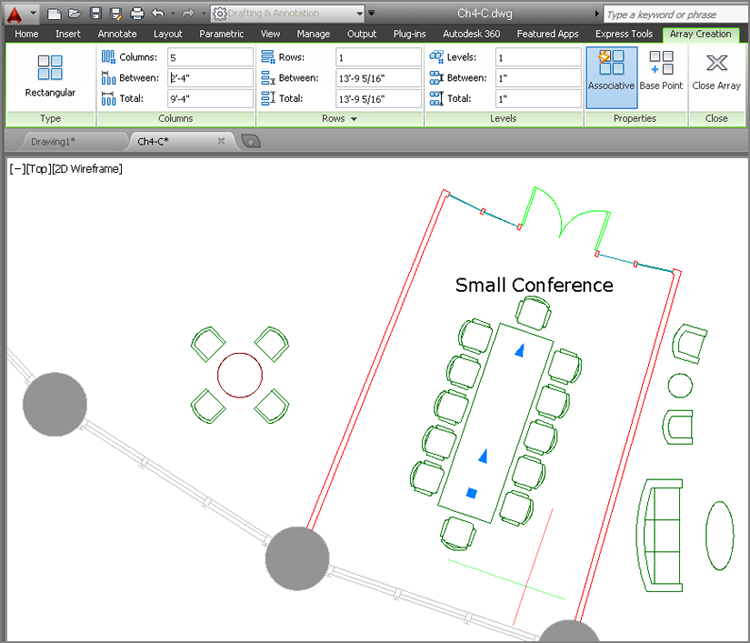
3. Click the Rectangular Array tool on the Modify panel. Select both chairs on the sides of the conference table and press Enter.
4. Change Columns to 5 and Rows to 1 on the temporary Array Creation tab that appears on the ribbon. Type
2′-4″ in the Between text box in the Columns panel (see
Figure 4-19). Depending on which side of the line you selected in the previous step, you might have to enter 1 Column and 5 Rows if the UCS is 180 degrees out of phase.
5. Select the Associative toggle in the Properties panel if it is not already blue. Click Close Array on the ribbon.
6. Select one of the new chairs, and observe that all the arrayed chairs are selected as a unit. Change the number of Columns to 4 and Between to 3′-0″ (90 for metric) and the five chairs along each side of the table are replaced by four.
7. Type UCS, and press Enter twice to return to the world coordinate system.
8. Save your work as Ch4-D.dwg (or Ch4-D-metric.dwg).
Polar Arrays
Polar arrays are used for rotating and copying objects around a common central point. Let’s create a polar array:
1. If the file is not already open from performing the previous step, go to the book’s web page, browse to Chapter 4, download the file Ch4-D.dwg (or Ch4-D-metric.dwg), and open it.
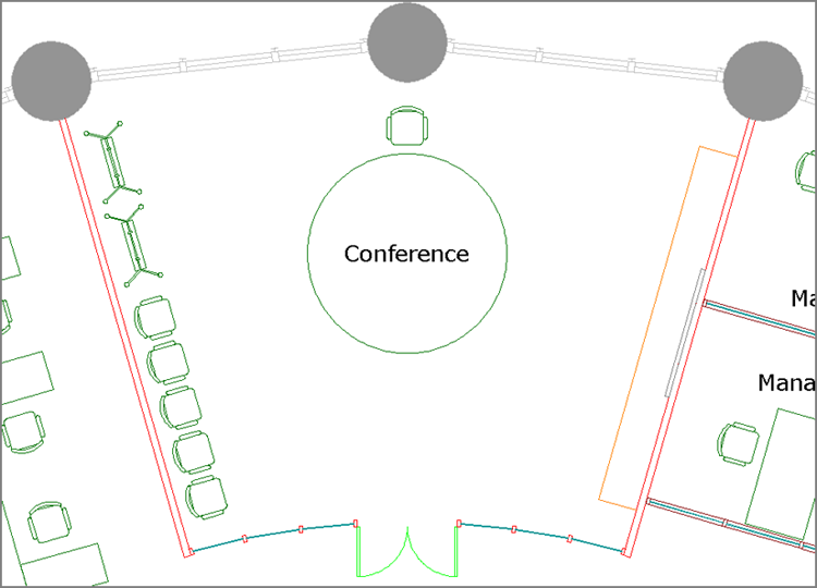
2. Navigate to the Conference room at the top of the plan (see
Figure 4-20).
3. Type AR (for Array), and press Enter. Select the chair at the top of the round table, and press Enter.
4. The command prompt reads as follows:
Enter array type [Rectangular Path Polar] <Rectangular>:
5. Type PO (for Polar), and press Enter.
6. Hold down Shift, and right-click to open the Object Snap context menu. Choose Center, and click the table’s center to set the center point of the array.
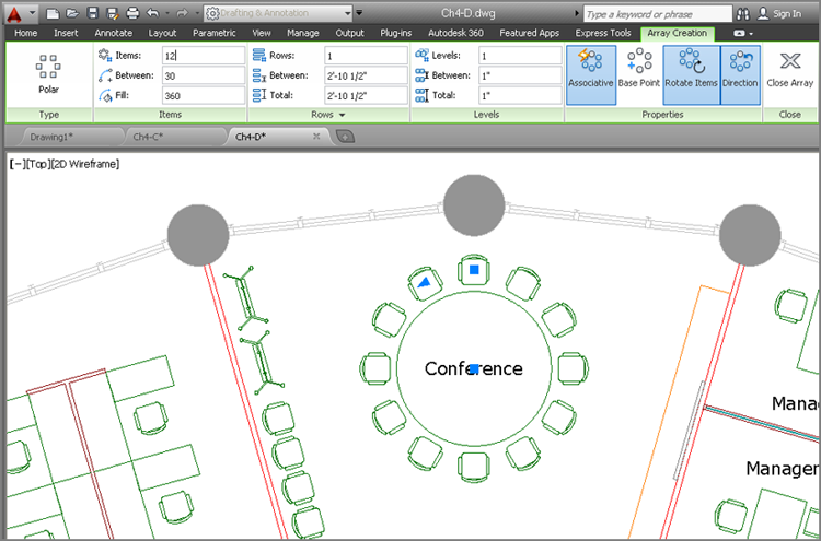
7. Type
12 in the Items text box on the ribbon. Toggle on Associative, Rotate Items, and Direction if they are not already on in the Properties panel (see
Figure 4-21). Click Close Array.
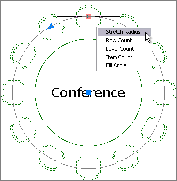
8. The table is a bit too large. Click the circle to select the table. Click the circle’s top blue quadrant grip, and move the cursor down. Type 4′6″ (or 140 in metric) to set a new radius. Press Enter and then Esc.
9. Click any one of the chairs to select the polar array. Hover the cursor over the base point grip, and choose Stretch Radius (see
Figure 4-22). Type
5′9″ (or
175 in metric); then press Enter and Esc. The chairs more closely wrap around the smaller table.
10. Save your work as Ch4-E.dwg (or Ch4-E-metric.dwg).
Divide and Measure
The DIVIDE and MEASURE commands do not copy objects in a rectangular grid or around a center point as does the ARRAY command. Instead, these commands are used for arraying points. DIVIDE splits up a path into any number of evenly spaced points. MEASURE lays out points at a set distance, often leaving a remainder at the end of a path. You’ll use DIVIDE in Chapter 5, “Shaping Curves.”
Trim and Extend
The TRIM and EXTEND commands are opposites. You can invoke the opposite command while running either by holding down Shift. This method is especially helpful because TRIM and EXTEND are often used together, as you’ll see in this procedure:
1. If the file is not already open from performing the previous step, go to the book’s web page, browse to Chapter 4, download the file Ch4-E.dwg (or Ch4-E-metric.dwg), and open it.
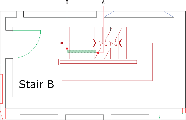
2. Navigate to Stair B in the building’s core.
3. Click the Extend tool on the Modify panel (it is nested under Trim). Select the inner line of the bottom core wall and press Enter. This line will be the boundary edge that you will extend the stair treads to meet.
4. Create a crossing window by clicking points A and B as shown in
Figure 4-23. Four tread lines are extended. Click each remaining tread line, one at a time, to extend all the stair treads to the core wall. Press Enter to end the command.
5. Type TR (for Trim), and press Enter. Select the upper and lower handrail lines to act as cutting edges and press Enter. Make a crossing window in the center of the handrail to trim away all the treads that pass through the handrails, and press Enter.
6. Press Enter twice more to repeat the TRIM command, and select all edges as potential cutting edges. Then click the single tread line that extends below the break line and press Enter. Stair B should now be the mirror image of Stair A.
7. Save your work as Ch4-F.dwg (or Ch4-F-metric.dwg).
Lengthen and Stretch
The LENGTHEN and STRETCH commands are similar in how they can increase the length of objects. However, STRETCH is the more flexible of the two, allowing you to reposition interconnected objects. Let’s lengthen a line and stretch a door within a wall:
1. If the file is not already open from performing the previous step, go to the book’s web page, browse to Chapter 4, download the file Ch4-F.dwg (or Ch4-F-metric.dwg), and open it.
2. Navigate to the Copy Room. Notice that there is a problem with the copy machine by the door; the bottom line is drawn only halfway. Although you could use
FILLET or
EXTEND to fix it, type
LEN (for Lengthen) and press Enter. The command prompt reads as follows:
Select an object or [DElta/Percent/Total/DYnamic]:
Type P (for Percent), and press Enter.
3. Type 200, and press Enter. Click the line segment on the right side to lengthen it toward the right. The copy machine is fixed!

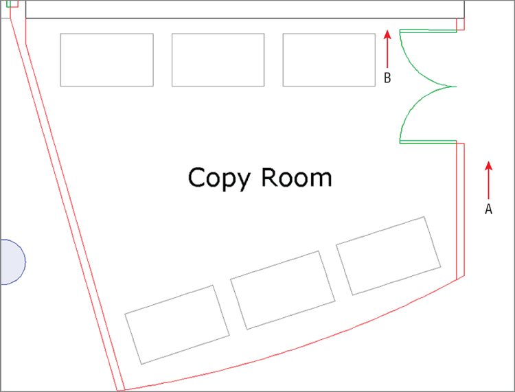
4. Type
S (for Stretch). The command prompt reads as follows:
Select objects to stretch by crossing-window
or crossing-polygon...
Select objects:
Implied windows won’t work for
STRETCH; only crossing windows or crossing polygons are acceptable. Click points A and B as shown in
Figure 4-24 to select the objects to stretch and press Enter.
5. Using either Polar Tracking or Ortho mode, move the cursor down vertically, type 2′6″ (or 75 for metric), and press Enter to specify the second point. The wall, door, and swing end up more or less centered on the wall.
6. Save your work as Ch4-G.dwg (or Ch4-G-metric.dwg).
Offset and Mirror
The OFFSET and MIRROR commands are often used to create new objects. OFFSET creates an object a set distance on one side of the original object. MIRROR creates a reversed object at a distance from the original object as determined by the position of a drawn reflection line. Let’s explore these commands:
1. If the file is not already open from performing the previous step, go to the book’s web page, browse to Chapter 4, download the file Ch4-G.dwg (or Ch4-G-metric.dwg), and open it.

2. Click the Offset tool in the Modify panel. The command line reads as follows:
Specify offset distance or [Through Erase Layer] <Through>:
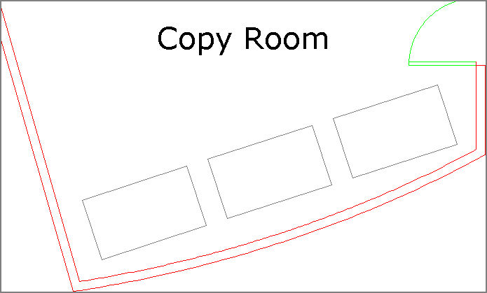
Type 4, and press Enter. Select the elliptical arc at the bottom edge of the Copy Room.
3. The command line asks you to specify a point to determine on which side of the selection to offset the new object. In this case, click anywhere above the elliptical arc and a new ellipse is created such that its curvature matches the original but is spaced 4 units away. Press Enter to exit the command.
4. Type
F (for Fillet), press Enter, and click the new elliptical arc and the inner line of the adjacent vertical wall on the right. Press the spacebar to repeat the
FILLET command, and click the elliptical arc and inner line of the adjacent vertical wall on the left. The intersections between the wall objects are cleaned up (see
Figure 4-25).
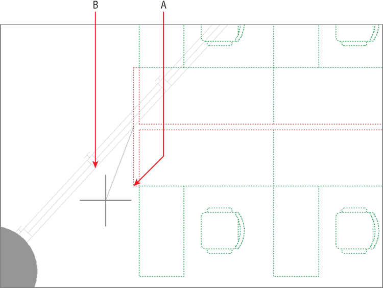
5. Zoom into the furniture system that is missing two desks in the upper-right quadrant of the building. Click the Mirror tool in the Modify panel. Make crossing and individual line selections to select the desks and chairs shown in
Figure 4-26, and press Enter. The command line reads as follows:
Specify first point of mirror line:
Click point A, and then move the cursor up and click point B to draw the mirror line. Press Enter to end the command.
6. Press Enter to repeat the MIRROR command. Double-click the mouse wheel to zoom to the drawing extents. Select the furniture system you rotated with the Reference option in the upper-right building quadrant and press Enter. For the first point of the mirror line, type 0,0 and press Enter.
The origin point is at the center of the sample office building.
7. Toggle on Polar Tracking, move the cursor horizontally to the left—beyond the building—and click to specify a horizontal mirror line. Press Enter to complete the command, and decline to erase the source object. A copy of the furniture system appears symmetrically in the lower-left building quadrant (see
Figure 4-27).
8. Save your work as Ch4-H.dwg (or Ch4-H-metric.dwg).
Grip Editing
All objects have grips, the square blue symbols that appear in AutoCAD at significant points when objects are selected without issuing any command. Grips provide an alternative means of accessing a number of editing commands, including STRETCH, MOVE, ROTATE, SCALE, and MIRROR. Let’s explore grip editing:
1. If the file is not already open from performing the previous step, go to the book’s web page, browse to Chapter 4, download the file Ch4-H.dwg (or Ch4-H-metric.dwg), and open it.
In Reception, the sofa seating group is oriented horizontally, but this doesn’t respond to the geometry of the space.
2. Select the inner line of the window wall directly below the sofas, right-click, and choose Properties from the context menu. Make a note that the angle of this line is 173.77 degrees. Press Esc to deselect.
3. Click both sofas and the coffee table in between them to select all three. Single blue grips appear on the sofas because they are blocks (see Chapter 7, “Organizing Objects,” for more on blocks).
4. Click this grip in the center of the coffee table to activate it. The command prompt reads as follows:
ff STRETCH ff
GRIP_STRETCH Specify stretch point or [Base point Copy Undo eXit]:
Press the spacebar. The command prompt changes to:
ff MOVE ff
GRIP_MOVE Specify move point or [Base point Copy Undo eXit]:
5. Press the spacebar again. The command prompt now says:
ff ROTATE ff
GRIP_ROTATE Specify rotation angle or
[Base point/Copy/Undo/Reference/eXit]:
6. Type 'CAL to invoke the command-line calculator transparently. Type 173.77-180, and press Enter to have AutoCAD calculate the negative rotation angle for you (-6.23 degrees in this case). Remember that negative angles rotate objects clockwise by default. The seating group rotates to match the orientation of the window wall that it is in front of.
Using an apostrophe before a command issues it transparently so that it works on top of another command without canceling it.
7. Press Esc to deselect all.
Figure 4-28 shows the final result.
The Essentials and Beyond
In this chapter, you learned how to edit drawings first by making selections, and then by moving, copying, rotating, and scaling objects. You created individual and associative rectangular and polar arrays; used the Trim, Extend, Lengthen, Stretch, Offset, and Mirror tools; and edited with grips. In short, you learned how to draw in AutoCAD. Congratulations are in order!
Additional Exercise
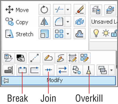
- Explore the BREAK, JOIN, and OVERKILL commands on your own. As the name suggests, the Break tool is used to interrupt an object at one or two points (leaving a gap). Join is used to connect two or more collinear lines into single segments. Overkill eliminates coincident lines. All three are used to clean up drawings.