
Chapter 7
Character Modeling Part I
In games, characters are cleverly designed and created to achieve the best look with the least amount of mesh detail to keep the polygon count low. Drawing on this knowledge, the film industry has taken many game-modeling techniques and modified them for film, creating low-poly efficient models and then adding detail (or polygons) when needed. With that in mind, this chapter and the next introduce you to character modeling, using the Editable Poly toolset to create a cute alien suitable for character animation. The alien character used in this book was designed by Andrew Montemayor, a graduate of the Art Institute of California - Los Angeles, who specializes in storyboarding, character design, and background design.
This chapter begins with the basic form of the character.
In this chapter, you will learn to:
- Set up the scene
- Block out the alien body
- Refine the alien body
Setting Up the Scene
You can import and use sketches of the character’s front and side as background images as you create the character using the Autodesk® 3ds Max® software toolset. You can use additional sketches of your character from several points of view as quick references to help you reach your goal.
Exercise 7.1: Creating the Image Planes
You’ll begin this exercise by creating crossed boxes and applying reference images to them. Set your project to the c07_CharacterModel project you downloaded from the book’s web page at www.sybex.com/go/3dsmax2015essentials.
- In a new scene, select the Front viewport.
- In the Create panel ⇒ Geometry, select Plane. Select the Keyboard Entry rollout and set Y: to 30. This will move the bottom of the plane in line with the 0 axis within the front view. Set Length to 60 and Width to 42. Click the Create button.
- Rename the plane Image Plane Front.
- With the plane still selected, choose the Modify tab, and in the Parameters rollout, set Length Segs and Width Segs to 1.
- Click in a blank space in the user interface (UI), and then press Ctrl+Shift+Z on your keyboard to initiate the shortcut for Zoom Extents All.
- In the main toolbar, turn on Angle Snap Toggle (
 ) or press A on your keyboard. Doing so will snap your rotation to every 5 degrees.
 - Select the Select and Rotate tool (E) and select the Image Plane Front object. Hold down the Shift key on the keyboard and, in the Front viewport, rotate the image plane by dragging along the Y-axis 90 degrees.
- Using the Shift key and a Transform tool activates the Clone Options dialog box, shown in Figure 7-1.
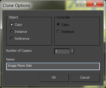
Figure 7-1: The Clone Options dialog box
- In the Clone Options dialog box, under Object, select Copy; name the copy Image Plane Side and click OK.
This is a good time to save your file. To check your work, open the c07_ex1_setup_end.max file in the c07_CharacterModel project folder.
Exercise 7.2: Adding the Images to the Planes
At this point, you add the reference materials onto the planes to provide a reference inside the scene itself while you model the character. Therefore, it’s critical to ensure that the features of the character that appear in both reference images (the front and the side) are at the same height. For instance, the top of the head and the shoulders should be at the same height in both the front and side views to make the modeling process easier. Either continue the exercise using your previously saved file or open c07_ex2_image_start.max.
- Change the shading in the Front and Left viewports to Shaded if it isn’t already set to Shaded. Turn off the grid in both viewports by selecting the viewport and using the keyboard shortcut G.
- Open a Windows Explorer window and navigate to the
c07_CharacterModel/sceneassets/imagesfolder on your hard drive. - Drag
Alien_Front.jpgfrom the Explorer window to the Image Plane Front object in the Front viewport. - Drag
Alien_Side.jpgonto the Image Plane Side object in the Left viewport. - Turn on Edged Faces; you can use the keyboard shortcut F4. The image planes should have the two images mapped on them, as shown in Figure 7-2.
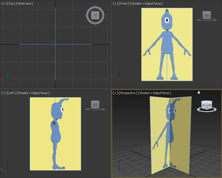
Figure 7-2: Mapped image planes in viewports
To check your work, open the c07_ex2_image_end.max file in the c07_CharacterModel project folder.
Blocking Out the Alien Model
When starting a model a good practice is to block out the basic form of the character and focus on the size and crucial shapes of the major elements; and then add detail for the finer features. The following exercises describe the steps required to block out the alien’s major features.
Exercise 7.3: Forming the Torso
The basic structure for the torso begins with a simple box primitive. After converting the box into an editable poly, you will use the Symmetry modifier on the object so that any manipulations performed on one side are also performed on the other. You will begin forming the basic shape of the torso by moving the editable poly’s vertices and extruding its polygons in the following steps. Continue with the previous exercise’s scene file, or open the c07_ex3_torso_start.max scene file in the scenes folder of the c07_CharacterModel project folder downloaded from this book’s web page. Then follow these steps:
- In the Perspective viewport, select the Shading viewport label menu and choose Shaded, and then press F4. This will turn on Edged Faces; do this if it isn’t already set that way.
- Start by creating a box primitive in the Perspective viewport with these parameters: Length: 9, Width: 10, Height: 19, Length Segs: 3, Width Segs: at 2, and Height Segs: 4, as shown in Figure 7-3.
- Press Alt+X to make the box see-through.
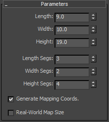
Figure 7-3: Box parameters
- Change the box’s name to Alien Body.
- Position the box at X: 0, Y: 0.0, Z: 22.0 so it is aligned with the Alien’s torso, as shown in Figure 7-4.
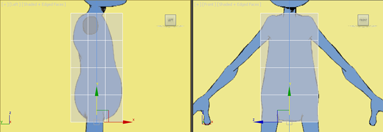
Figure 7-4: Box position from the front and side views
- In the Ribbon ⇒ Modeling tab ⇒ Polygon Modeling panel, click Convert To Poly.
- In the Polygon Modeling panel, enter the Vertex sub-object level.
- In the Left viewport, select and move the vertices to match the outline of the character on the image plane, as shown in Figure 7-5. Use a selection box to select the vertices from the Left viewport. This will ensure that you are selecting both the back vertex and the vertex that can be seen in the viewport.
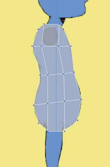
Figure 7-5: Move the vertices to match the alien’s image in the Left viewport.
- In the Polygon Modeling panel, enter Polygon sub-object level.
- In the Front viewport, drag a selection marquee around the right half of the box and delete it. The reason for doing this is to cut your work in half. You will build half of the body and then copy it to the other side.
- In the Polygon Modeling panel, enter Vertex sub-object level.
- Move the vertices to match the outline of the character from the Front view, as shown in Figure 7-6.
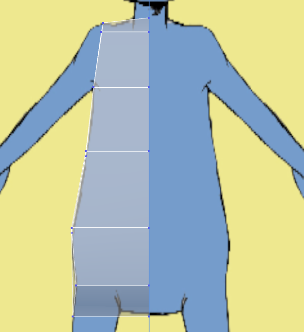
Figure 7-6: Move the vertices to match the alien’s image in the Front viewport.
- From the Front viewport, select the vertices on the front outside edge and move them closer to the center, as shown in Figure 7-7. Click the Vertex button again to exit Vertex mode.
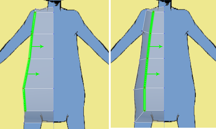
Figure 7-7: Select and move vertices towards the center of the model.
- In the Ribbon ⇒ Modeling tab ⇒ Edit ⇒ SwiftLoop, place a new loop on the inside, as shown in Figure 7-8. You will use this loop when you build the alien’s leg.
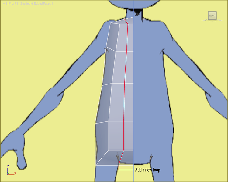
Figure 7-8: Use SwiftLoop to place an edge on the model.
In this section you are just building the torso and setting things up for the following exercises. Save the file; to check your work against ours, open the c07_ex3_torso_end.max file in the c07_CharacterModel project folder.
Exercise 7.4: Creating Symmetry
So far, you’ve modeled only one half of the torso; you will use a modifier to copy the half torso and mirror it to create the rest of the torso. Continue with the previous exercise’s scene file, or open the c07_ex4_symmetry_start.max scene file in the scenes folder of the c07_CharacterModel project downloaded from this book’s web page.
- Select the alien torso, and in the Modify panel choose Symmetry from the Modifier list. When the modifier is applied, the model will disappear; this is because of the default parameters in the modifier.
- In the Parameters section check the Flip box in the Mirror Axis area, as shown in Figure 7-9.

Figure 7-9: The Symmetry modifier creates a full torso.
- Go to the Modify panel, and in the modifier stack select Editable Poly.
- In the Ribbon ⇒ Modeling tab ⇒ Edit, select Use NURMS. This will show the model with smoothing, but because the Symmetry modifier is still active, the end result is not shown, so you see only half the model smoothed.
- From the modifier stack on the toolbar select the Show End Result On/Off Toggle button (
 ), to show the effect of the entire stack. Now the whole model is visible, as shown in Figure 7-10.
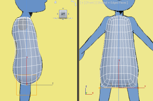
Figure 7-10: The alien model with the Symmetry modifier and Use NURMS applied
The model with Use NURMS applied reveals some problems. In the next exercises you will begin blocking out the arms and refining the torso. Save the file; to check your work, open the c07_ex4_symmetry_end.max file in the c07_CharacterModel project folder.
Exercise 7.5: Blocking Out the Arms
The arms for the alien are skinny and slightly longer than a human’s arms, but other than that they are similar, with hands, wrists, elbows, and so on. Thus the alien arms will have three sections: upper arm, lower arm, and hand. Continue with the previous exercise’s scene file, or open the c07_ex5_arm_start.max scene file in the scenes folder of the c07_CharacterModel project folder.
- Start by removing the Symmetry modifier by right-clicking the modifier and choosing Delete from the menu. Then from the Ribbon ⇒ Modeling tab ⇒ Edit, turn off Use NURMS.
- Move the Image Plane Front object back along the Y axis to 20.0.
- On the Ribbon ⇒ Modeling tab ⇒ Polygon Modeling panel, enter Polygon mode.
- From the Left viewport select the polygon where the armhole is, as shown in Figure 7-11.
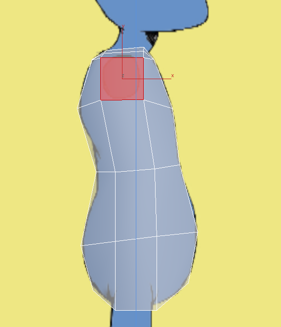
Figure 7-11: Select the polygon in the armhole location.
- Switch to the Front viewport, and in the Ribbon ⇒ Modeling tab ⇒ Polygons panel choose Bevel ⇒ Bevel Settings. Use the default setting, which is Bevel Height: 10.0 and Bevel Outline: -1.0, as shown in Figure 7-12. Click OK.
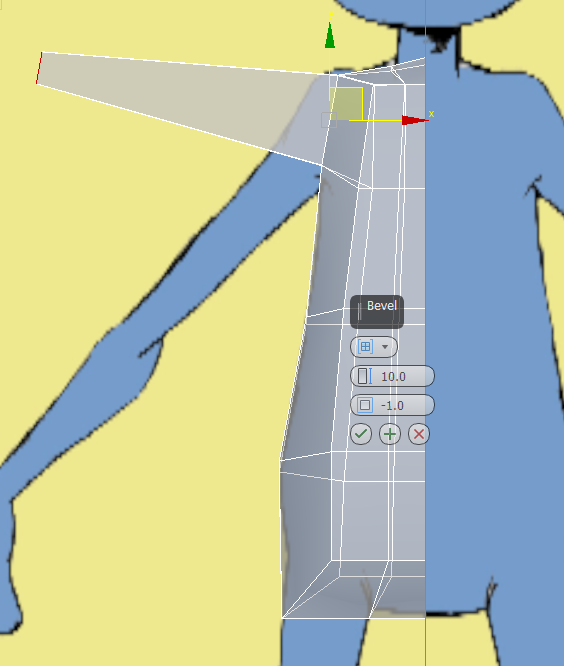
Figure 7-12: Position the arm with the image plane.
- Use the Move tool to position the new extruded arm to line up with the front view image.
- Select the Rotate tool and rotate the selected polygon 65 degrees on the Z axis, as shown in Figure 7-13.
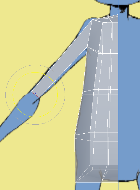
Figure 7-13: Rotate the polygon 65 degrees.
- The polygon at the end of the arm should still be selected, so select the Ribbon ⇒ Modeling tab ⇒Polygons panel ⇒ Bevel ⇒ Bevel Settings. Change the settings on this first bevel to Bevel Height: 1.0 and Bevel Outline: 0.5. Click Apply and Continue. Then set the second bevel to Bevel Height: 6.5 and Bevel Outline: -0.5, as shown in Figure 7-14. Click OK.
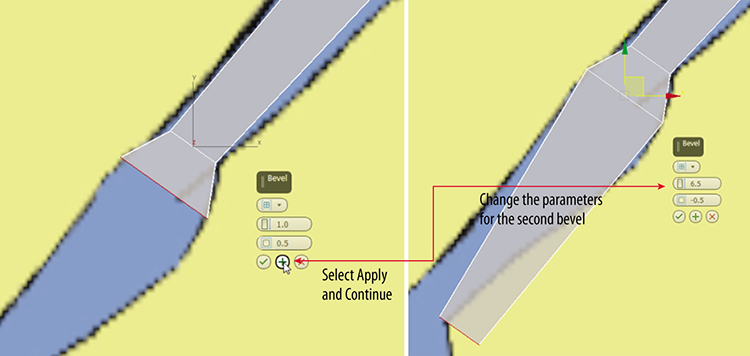
Figure 7-14: Bevel settings for completing the arm to the wrist
- Use the Move tool to line up the arm with the front view image at the wrist.
- In the Ribbon ⇒ Modeling tab ⇒ Edit, select Use NURMS; now the problems with arms are more evident, as shown in Figure 7-15. Turn off Use NURMS, because it is easier to fix these issues on the rough model.
- Enter Vertex mode, select the vertex at the armpit, and move it down to line up more accurately with the image plane, as shown in Figure 7-15.
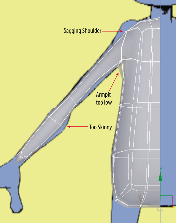
Figure 7-15: Problems with the model are more evident with Use NURMS active.
- Repeat the process on vertex at the shoulder and lower arm. Turn on Use NURMS again and adjust further. Some parts of the model will not look correct even with the changes. More subdivisions need to be added.
- Select the Ribbon ⇒ Modeling tab ⇒ Edit ⇒ SwiftLoop, and add a loop below where the shoulder begins and another a bit below that. You should still be in Vertex mode, so move the vertices again to better match the image plane, as shown in Figure 7-16. Do all this with Use NURMS turned on. When you have finished, turn off Use NURMS.
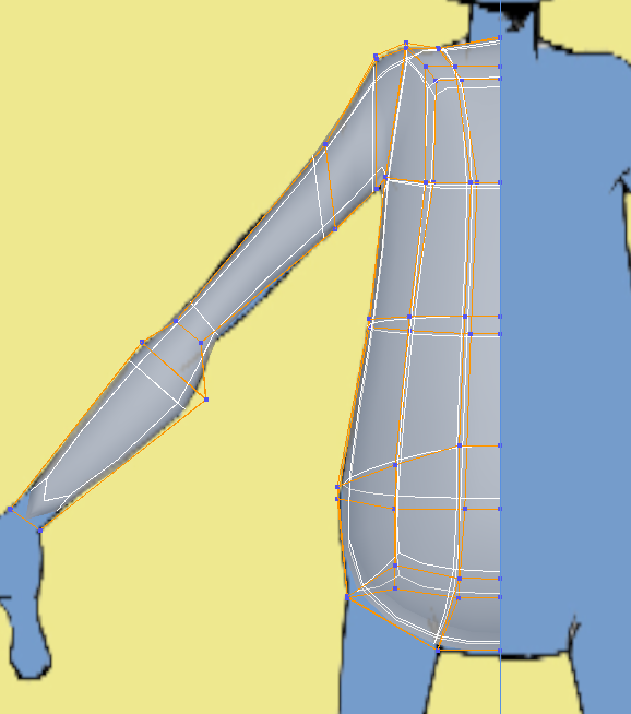
Figure 7-16: Use SwiftLoop to add edges to fix problems with the model.
Now you are starting to see some shape in the torso and arm. Save the file. To check your work, open the c07_ex5_arm_end.max file in the c07_CharacterModel project folder.
Exercise 7.6: Blocking Out the Leg
The legs for the alien are exactly like a human’s legs with three sections: upper thigh, knee, and calf. For the leg modeling you will use a different technique than you used for the arm. The method has no official name, so for this chapter it will be called the Shift+Move Extrude method. This method is similar to using the Extrude or Bevel tools and works only with Border and open-ended Edges modes. For this chapter you will use the Border mode. Continue with the previous exercise’s scene file, or open the c07_ex6_leg_start.max scene file in the scenes folder of the c07_CharacterModel project folder.
- In the Perspective viewport, select the model. Enter Polygon mode and select the polygon at the bottom of the model, as shown in Figure 7-17.

Figure 7-17: Select the polygon at the bottom of the alien model to begin blocking out the leg.
- Delete the polygon.
- Enter Border mode (
 ).
).
- Enter Border mode (3 is the keyboard shortcut) of the deleted polygon if it is not already selected.
- Press W on the keyboard to access the Move tool.
- While looking through the Front viewport, hold Shift on the keyboard and move the border down until it sits at the center of the alien’s thigh.
- Switch to the Scale tool (R) and scale the border down so it matches the width of the thigh in the image plane, as shown in Figure 7-18.
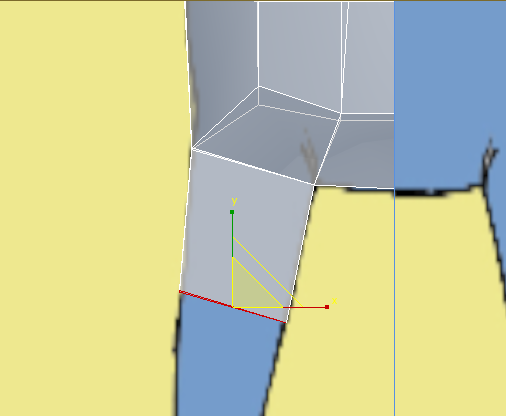
Figure 7-18: Use Scale to change the width of thigh, and then use the Shift+Move Extrude method to extrude the thigh.
- Switch to the Left viewport and adjust the model to match the image plane.
- Repeat the Shift+Move Extrude method to extrude down to just above the knee.
- Use the Scale and Move tools to adjust the position and size of that section of the leg to match the Front and Left viewports, as shown in Figure 7-19.
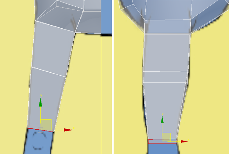
Figure 7-19: The left side image shows the leg from the Front viewport, and the right side image shows the leg from the Left viewport.
- Use the Shift+Move method again and extrude the leg a small amount in the middle of the knee area, and then repeat to extrude just below the knee.
- Use the Scale and Move tools to adjust the position and size of that section of the leg to match the Front and Left viewports.
- Repeat the Shift+Move method and extrude to the center of the calf; repeat to extrude to above the ankle.
- Switch to Vertex mode, and move vertices to further adjust the model to match the image planes from the front and left views, as shown in Figure 7-20. Exit Vertex mode by clicking the Vertex button in the Ribbon ⇒ Modeling tab ⇒ Polygon Modeling.
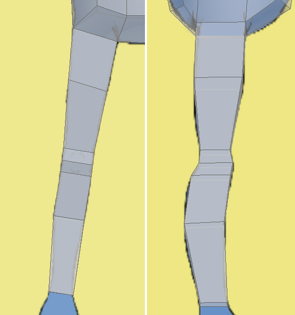
Figure 7-20: Front view of the completed leg (left image); left view of the completed leg (right image)
- 15. Go to the Ribbon ⇒ Modeling tab ⇒Edit ⇒ Use NURMS.
- In the Modify panel ⇒ Modifier List, choose the Symmetry modifier. Check the Flip box to see the whole model.
- Press Alt+X to exit See-Through mode.
- At the bottom of the interface, select the Isolate Selection Toggle button (
 ).
). - Exit Edged Faces mode by selecting a viewport and pressing F4 on the keyboard. Repeat this in all viewports.
- Enter Polygon mode, select the polygon at the end of the arm, and delete it. This will create the same look as at the bottom of the leg. The completed model is shown in Figure 7-21.
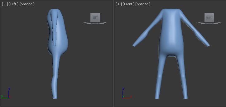
Figure 7-21: The completed model shown from the Left and Front viewports
The completed model looks pretty good. The body itself isn’t all that exciting. The alien has a soft and blobby body—too much junk food and not enough exercise. There are a few details that need to be refined. The area where the arm and chest meet is too squared off; this transition needs to be smoothed out. The chest needs some simple breast detail. The knees need more definition. The alien has no backside; it looks just like the front. So adding some shoulder blades and some backside definition will help, like a butt crack—sorry to have to be blunt! Save the file. To check your work, open the c07_ex6_leg_end.max file in the c07_CharacterModel project folder.
Exercise 7.7: Refining the Body
Some of the areas to refine are the knees, groin, chest, shoulders (front and back), and backside, as shown in Figure 7-22. Continue with the previous exercise’s scene file, or open the c07_ex7_body_start.max scene file in the scenes folder of the c07_CharacterModel project folder. This file has the alien model isolated. The Symmetry modifier has been removed and Use NURMS is turned off. If you are using your own file, exit Isolate mode, remove the Symmetry modifier, and turn off Use NURMS.
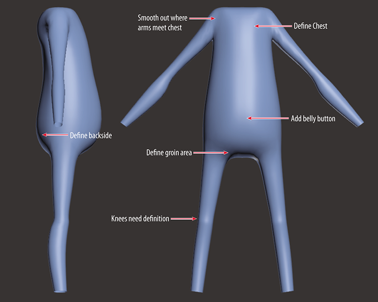
Figure 7-22: Areas to be refined on the model
Adding Detail to the Knee
The knee doesn’t need anything too complicated, just a few extra edges to add some detail.
- Select the model and enter Edge mode.
- Select the edge at the front of the knee.
- In the Ribbon ⇒ Modeling tab ⇒Edges ⇒ Chamfer ⇒ Chamfer Settings caddy, change Edge Chamfer Amount to 0.6, and click OK.
- In the Ribbon ⇒ Modeling tab ⇒Edit. At the bottom of the tab under Constraints, select Constrain to Edge (
 ).
).
- Switch to Vertex mode and from the Left viewport move the vertices at the back of the knee closer together, as shown in Figure 7-23. Make sure you drag a selection box around the vertices because from the Left viewport you see only the vertex facing the camera, but there is another vertex. You can also turn on See-Through mode so you can see both front and back vertices.
- Now move the vertices at the front of the knee to the right (from the Left viewport). You want the edges sticking out more, as shown in Figure 7-23. Click the Constrain to None (
 ) button to exit Constraints.
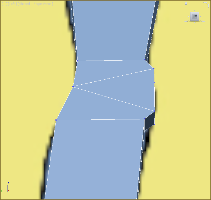
Figure 7-23: The knee vertices moved to add more detail
Refining the Groin Area
The alien doesn’t have any sex organs; the area just needs to be smoothed out and a crease needs to be added where the leg meets the body.
- Add an edge to the top of the thigh using SwiftLoop.
- Add another edge loop on the torso between the thigh and the center of the body. Refer to Figure 7-24 to see where it needs to be placed.
- Switch to Vertex mode and move the vertices (use the Constrain to Edge tool), as shown in Figure 7-24. These simple edges will add a very subtle crease at this area. To exit Constraints click the Constrain to None button.
- To see what the model looks like now, turn on Use NURMS. In the Use NURMS tab in the Ribbon ⇒ Modeling tab (Use NURMS can also be a floating menu) change Iterations to 2, as shown in Figure 7-25.
- Exit Vertex mode by selecting the Vertex icon in the Ribbon ⇒ Modeling tab ⇒ Polygon Modeling.
Did you think we were going to add something X-rated? Sorry! The alien is strictly G-rated.
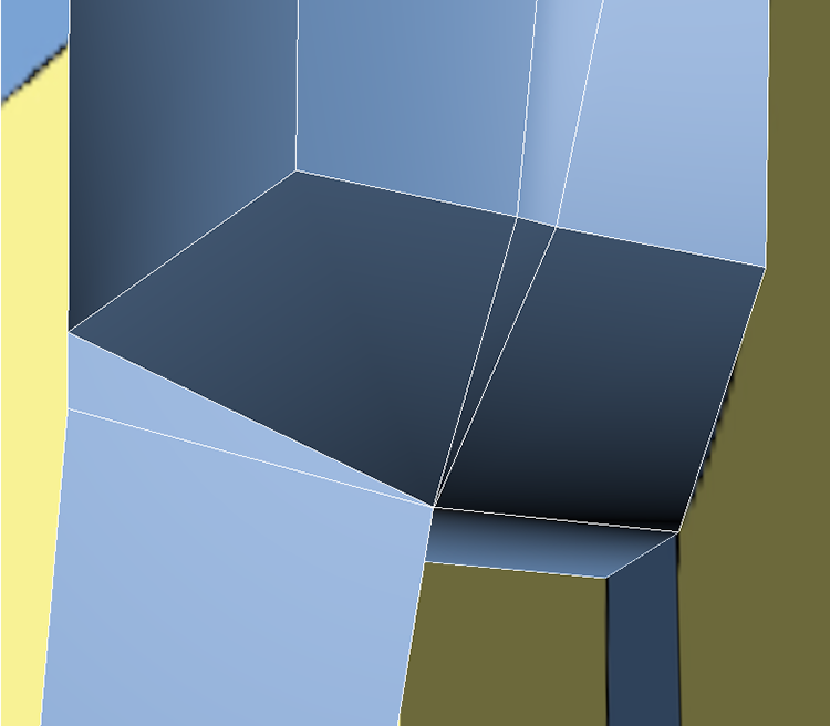
Figure 7-24: With vertices added, the groin area is more refined.
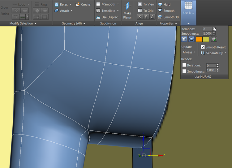
Figure 7-25: Groin area with Use NURMS active
Refining the Backside
The backside (or behiny as my seven-year-old says) looks very similar to the front, so to give it some distinction you will add a backside “crack,” a crease to set it apart from the front. Turn off Use NURMS to continue.
- Select the alien body and enter Isolate Selection mode.
- Using the ViewCube®, rotate the Perspective view so the backside can be seen.
- In the Modify panel ⇒ Modifier List, select the Symmetry modifier. Check the Flip box, and in the modifier stack select the Show End Results On/Off Toggle (
 ), which sits directly below the modifier stack. This will allow you to work on the model and see the other side of the model updating.
 - Enter Vertex mode.
- Select the vertex at the intersection of the backside and leg. Zoom in very close because the vertices are very close together. You will need to select the left side vertex closest to the model center, as shown in Figure 7-26.
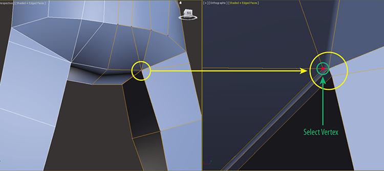
Figure 7-26: The left image shows the zoomed-out area; the right image shows the zoomed-in area where you need to select the vertex.
- In the Ribbon ⇒ Modeling tab ⇒ Edit ⇒ Constraints, select Constrain to Edge.
- Move the selected vertex toward the center of the model.
- Repeat the move on the two vertices directly above the vertex moved in step 7, as shown in Figure 7-27.
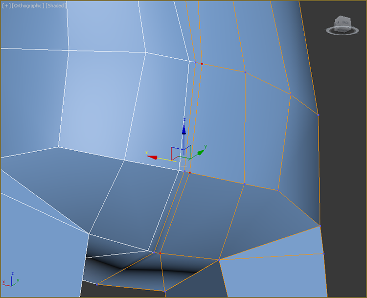
Figure 7-27: Move the three selected vertices closer to the center of the model.
- Select the three vertices at the center of the model.
- In the Ribbon ⇒ Modeling tab ⇒ Edit ⇒ Constraints, select Constrain to Normal. This will isolate the movement perpendicular to the model.
- Move the select vertices in toward the inside of the model.
- Turn on Use NURMS, and exit Vertex mode. Turn off Edged Faces in the Rendering Type menu, or use the keyboard shortcut F4. Click away from the model to deselect it; the completed backside is shown in Figure 7-28.
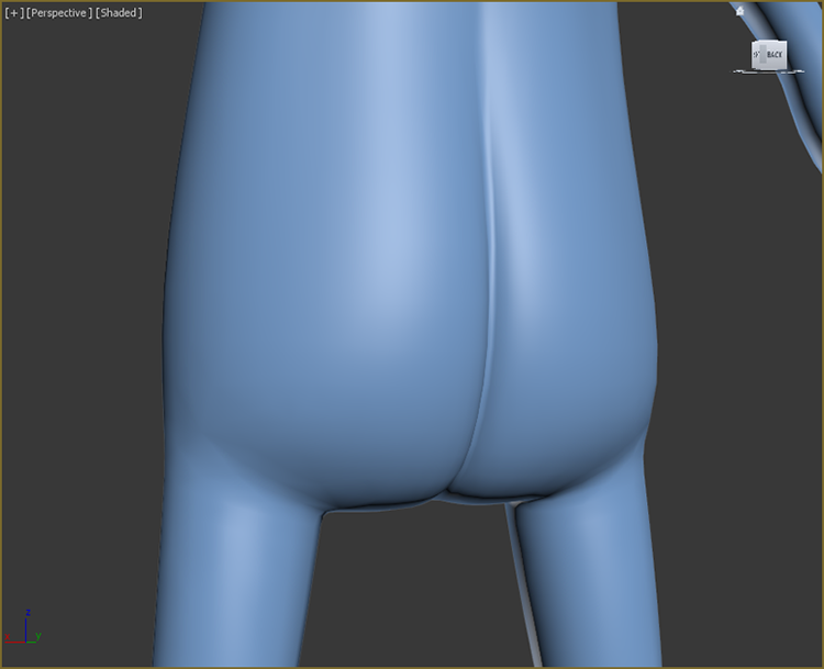
Figure 7-28: The completed backside of the alien
Remaining Refinements
At this point most of the things that need to be refined have been refined. There are a few things you can add using the same techniques used in the previous section. For example, you could add a few extra loops in the elbow area, as shown in Figure 7-29.
Some of the changes can’t be done to the model in separate halves with the Symmetry modifier active. This will be remedied in the following chapter. Save your file. To check your final results against ours, open the c07_ex7_body_end.max file in the c07_CharacterModel project folder. The final alien body is shown in Figure 7-30.
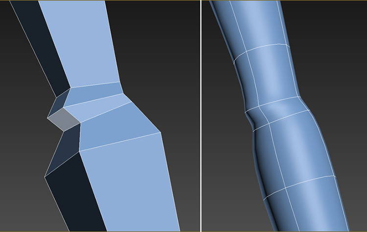
Figure 7-29: The left image shows the elbow with the loops added; the right image shows the changes with Use NURMS turned on.
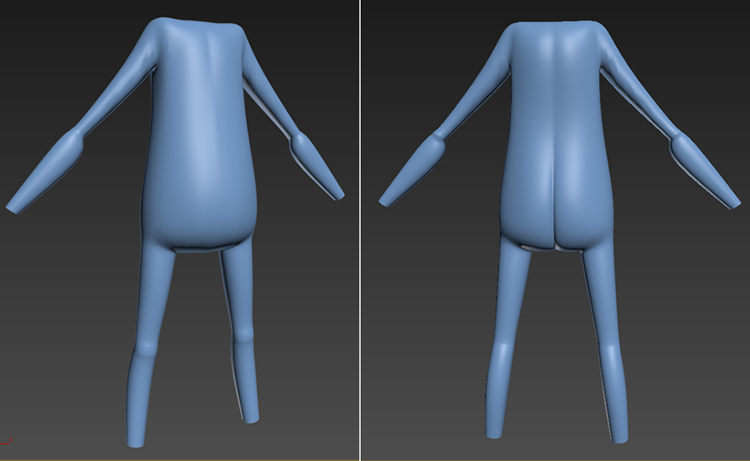
Figure 7-30: The final alien body; the left image is the front and the right image is the back.
Exercise 7.8: Building the Neck
Before building the head you have to build up the neck. Either continue with the exercise scene file from the previous section, or open the c07_ex8_neck_start.max scene file in the scenes folder of the c07_CharacterModel project folder on the book’s web page at www.sybex.com/go/3dsmax2015essentials. If you are continuing with your file, exit Isolate Selection mode.
- Select the alien body, go to the Modify panel, and in the modifier stack right-click the Symmetry modifier and choose Delete from the menu.
- In the Edit tab of the modeling ribbon, turn off Use NURMS.
- Enter See-Through mode (Alt+X).
- In the Polygon Modeling tab, enter Polygon mode. Select the two polygons where the neck would be placed and delete the polygons using the Delete key on the keyboard.
- In the Polygon Modeling tab, enter Edge mode.
- Select the edges where the polygons were deleted, as shown in Figure 7-31.
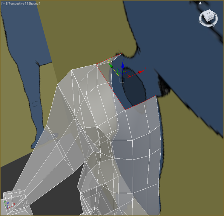
Figure 7-31: Select the edges around the neck hole.
- Switch to the Move tool (W) if it isn’t already selected.
- In the Left viewport, hold down Shift, and with the Move tool move the edges halfway up the neck and slightly forward, following the image plane (the Shift+Move Extrude method). Release the Shift key.
- Shift+Move again to extrude the edges to the top of the neck, as shown in Figure 7-32. Exit See-Through mode (Alt+X).
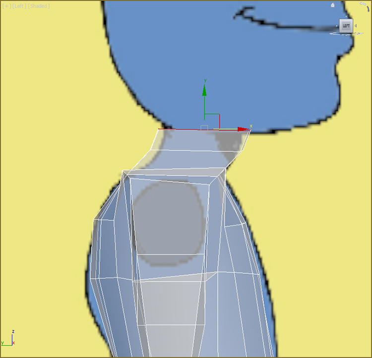
Figure 7-32: Use the Shift+Move Extrude method to create two more sets of polygons for the alien’s neck.
- The neck is too square. To round it out you will add another edge to the top of the arm and the side of the neck. In the Ribbon ⇒ Modeling tab ⇒ Edit tab ⇒ SwiftLoop, add a loop on the middle top of the arm, as shown in Figure 7-33.
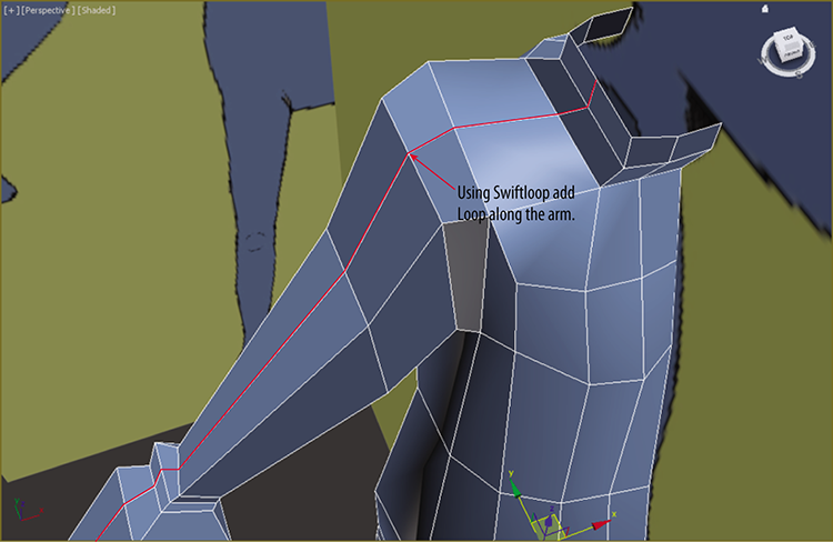
Figure 7-33: Using SwiftLoop, add a new edge to the top of the arm and neck to help in rounding out the neck.
- Enter Vertex mode; select and move the vertices at the neck to round out the neck, as shown in Figure 7-34.
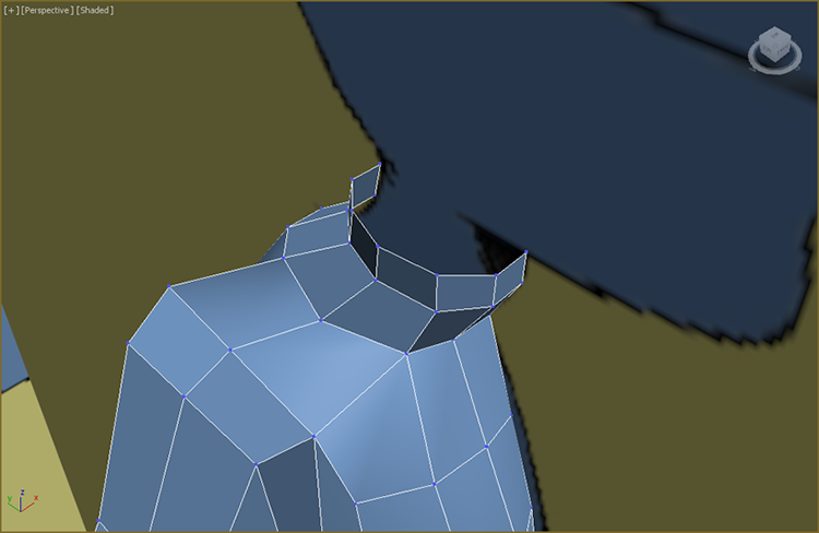
Figure 7-34: The adjusted shape of the neck
- Switch to the Front viewport, and enter See-Through mode.
- The area of the neck where it meets the shoulder needs more definition. In the Ribbon ⇒ Modeling tab ⇒ Edit tab, select SwiftLoop and add a loop between the lower loop at the neck and the loop at the shoulder. You can do this while still in Vertex mode. Exit SwiftLoop by right-clicking in the selected viewport.
- From the Front viewport move the vertices to better follow the neck and shoulder in the image plane, as shown in Figure 7-35. Exit See-Through mode.
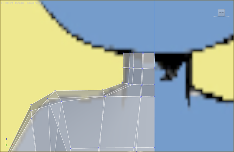
Figure 7-35: Adjust the vertices to match the neck of the alien in the image plane.
- The arm needs to be adjusted. The new loop that runs down the arm will flatten it out when NURMS is applied. So, select the vertices running down the outside of the arm and move them up so that the inside edge is higher than the outside edges, as shown in Figure 7-36.
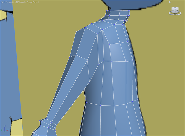
Figure 7-36: Move up the vertices on the outside of the arm to round out the top of the arm.
- Exit Vertex mode. Check the model by turning on Use NURMS. The final neck and arm are shown in Figure 7-37.
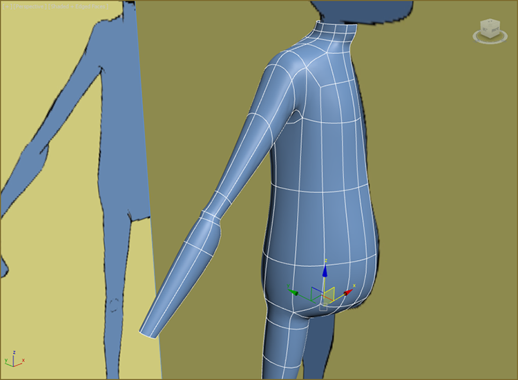
Figure 7-37: Final neck and arm
Save the file you are working with. To check your work open the
c07_ex8_neck_end.maxscene file in thescenesfolder of thec08_CharacterModelproject folder.