
Chapter 4
Modeling in 3ds Max: Architectural Model Part II
In this chapter, you will continue working within the interior design subject from the previous chapter by modeling and adding some furniture—specifically, a couch and chair.
In this chapter, you will learn to:
- Model a couch
- Model a lounge chair
Model the Couch
When you are starting a modeling project, make sure you have plenty of measurements, like those in the photo of the couch that will be modeled in this chapter, shown in Figure 4-1. Always remember to reference images for your modeling project. Modeling this couch is a straightforward process. If you break it down into separate components, it is just 16 different-sized boxes. The boxes are soft and cushy; they have various details, but nonetheless they are still just boxes, with the exception of the chaise lounge end of the couch, which is the only piece that isn’t a box shape.
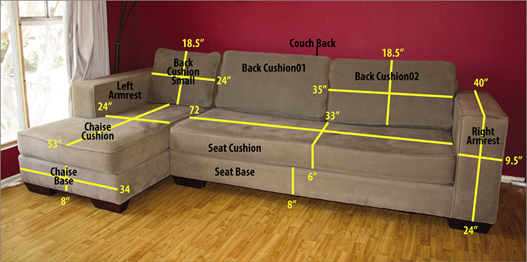
Figure 4-1: Couch with measurements
Exercise 4.1: Blocking Out the Couch Model
Blocking out the model means creating a simpler version of the model starting with whatever primitives fit the bill—in this case, boxes. Using the measurements shown in Figure 4-1, you will create a series of boxes and then orient them to mimic the couch. The first piece you’ll create is the bottom (the part between the seat cushions and the feet). It is 8 inches high by 72 inches wide by 33 inches deep. In the previous chapter, you used standard units of measurement (feet and inches), but for this chapter, you will use the default generic units. If your units are still set to feet and inches, refer to Exercise 3.1, “Setting Up Units,” in Chapter 3, “Modeling in 3ds Max: Architectural Model Part I,” to review how to change the setting to generic units. Then follow these steps:
- Open a new file in your Autodesk® 3ds Max® software, and select the Perspective viewport. Then go to the command panel and choose Create ⇒ Geometry and click Box.
- In the Keyboard Entry rollout, enter 33 for Length, 72 for Width, and 8 for Height, but don’t change the XYZ Type-In boxes.
- Click the Create button.
- The box should be in the center of the scene. Rename the box Seat Base.
- Create the cushion above this box: Select the box with the Move tool, and then hold Shift and move the box up in the Z-axis to create a new box so that it is on top of the old box. This is a quick method you can use to clone an object. The Clone Options dialog box will appear, as shown in Figure 4-2.
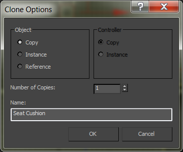
Figure 4-2: The Clone Options dialog box
- In the Clone Options dialog, select Copy. Change the name from Box to Seat Cushion and click OK.
- Go to the Modify panel and change the Height of the new cushion box to 6.0.
- As in step 1, create another box, but change the parameters to 40 for Length, 9.5 for Width, and 24 for Height. Rename the box Right Armrest.
- Move the box so it sits on the right side of the two stacked boxes.
- Create a clone for the left side of the couch using the same Shift and Move technique you used in steps 5 and 6.
- Now for the back piece: this is the part the back cushions rest against. You don’t see it in the picture in Figure 4-1, but it is there. Create a box with Length set to 6, Width set to 96, and Height set to 27. Move it behind the seat-cushion boxes to form the backrest, as shown in Figure 4-3 (left).
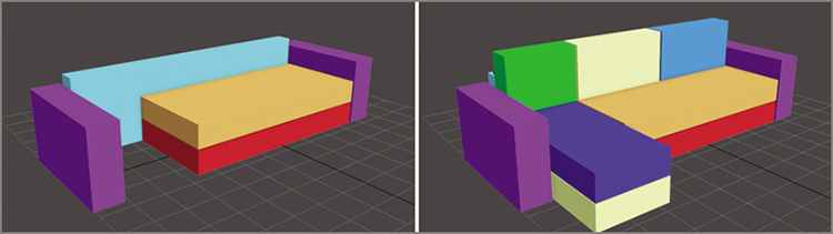
Figure 4-3: The first few pieces to start the couch (left); the blocked-out couch (right)
- Select the Perspective viewport. Choose the Create panel ⇒ Geometry and select Box, and in the Keyboard Entry rollout, input 53 for Length, 24 for Width, and 8 for Height. Click the Create button.
- Move the new box to the left of the seat cushions: Hold Shift and move the new box up so it is sitting on the old box. Choose Copy from the dialog box, and then change the box’s height to 6.0.
- Create another box with the following measurements: Length = 8, Width = 35, and Height = 18.5. Click the Create button to create a box for the back pillows.
- Move the box so that it is sitting on top of the seat cushions and against the right armrest.
- Make a clone of this box and move it to the left, so it is next to the other pillow.
- Make one more clone, and move it to the left so it sits on top of the chaise seat cushions. This box is too wide. With the box selected, go to the Modify panel and change Width to 24.0.
- Create three backrest cushions (two the same size and one that is smaller). As you are creating the couch pieces, name them. Refer to Figure 4-1 for the measurements and names.
- Once the cushions are created, move them into place on the couch to finish blocking out the couch, as shown in Figure 4-3 (right).
Save the file, and to check your work you can open c04_ex1_block_end.max from the scenes folder of the c04_ArchModel project files from the companion web page at www.sybex.com/go/3dsmax2015essentials.
Exercise 4.2: Using NURMS to Add Softness
Non-Uniform Rational Mesh Smooth (NURMS) is a subdivision surface technique that allows you to take a low-poly model and smooth the surface into a high-poly model. This isn’t a lighting trick; you are actually changing the geometry of the model. When you apply NURMS to your model, you will see a control cage in the shape of the low-poly model; this is the mesh you actually model.
Subdivision increases the poly count of your model; every level of subdivision increases the number of polygons by a factor of four. At a subdivision level (or iteration) of 1, 1 polygon in the control cage will become 4 polygons in the subdivided model. At an iteration level of 2, that 1 polygon becomes 16 polygons, and so on. When you’re working on a model with NURMS, it is best to work with a lower iteration level and then render with a higher level of iterations.
Polygons are flat between the vertices, but when NURMS is turned on, a flat polygon starts to curve and smooth out as it subdivides. When you use NURMS smoothing, the more distance there is between the edges on a mesh, the smoother the result will be. When you want sharp corners, just place the edges close together. When turning on NURMS, those close edges will retain their sharpness better. If you want a smoother, more rounded surface, then place the edges farther apart.
The best way to model with smooth surfaces is to use quad polygons in a grid formation; two edges will cross each vertex—and because each edge flows from vertex to vertex uninterrupted, the edges will continue and the 3D form will be smoothed predictably. If you have a vertex with no more than four edges coming out of it, the splines will end and the mesh may not smooth the way you expect it to.
All of the couch cushions will receive the same treatment, so let’s go over the next technique using one of the armrests of the couch and the chaise lounge section. After you’re finished with that, you can practice the techniques on the remaining couch boxes yourself. Continue with the file from the previous exercise or open the c04_ex2_NURMS_start.max file from the scenes folder of the c04_ArchModel project folder. Then follow these steps:
- Select the Right Armrest object. Click the Isolate Selection Toggle button (
 ).This turns off the view of the other objects in the scene to allow you to focus on this one piece.
 - In the Ribbon ⇒ Modeling tab, select Polygon Modeling ⇒ Convert To Poly.
- Then choose the Edit tab and click Use NURMS (
 ). You will see a box that looks like the air was let out of it, as shown in Figure 4-4.
 - Back in the modeling ribbon, select the Edit panel and click the Use NURMS button again to turn it off.
- In the Edit tab, click the SwiftLoop tool (
 ) and hover your cursor over the box to reveal a loop of edges on the box.
 - Place one of the lines shown in Figure 4-5 by clicking where you want the loop to be added on the box, and then place the other three loops, as shown in Figure 4-5. Right-click with your mouse to release the SwiftLoop tool.
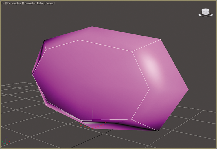
Figure 4-4: Couch armrest with NURMS applied
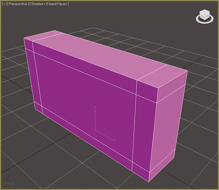
Figure 4-5: Use the SwiftLoop tool to add edge loops to the box.
- Turn on Use NURMS again to see the difference after using the SwiftLoop tool. Then turn Use NURMS off again to prepare for the next section.
- Save the file, and to check your work open
c04_ex2_NURMS_end.maxfrom thescenesfolder of thec04_ArchModelproject.
If you refer to the picture in Figure 4-1, you can see that the couch arm is even more squared off than the current mesh. In the next section, you will learn how to add more detail.
Exercise 4.3: Building Detail on the Couch Model
The next step in the process of creating the couch is to add the piping, which is the round decorative trim along the seams of the pillows, as shown in Figure 4-6. Continue with the file from the previous exercise or open the c04_ex3_detail_start.max file from the scenes folder of the c04_ArchModel project.
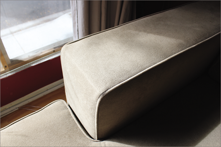
Figure 4-6: Decorative piping runs along the seams of the couch.
- Start by selecting the Armrest object. In the Edit tab, turn off Use NURMS. Then in the Polygon Modeling tab, enter Edge mode. Ctrl+click to select the edges on the box that are identified in Figure 4-7.
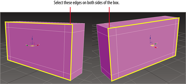
Figure 4-7: Select the highlighted edges.
- Go to the Edges tab, and open the Chamfer Settings caddy. Change Edge Chamfer Amount to 0.15, press Enter on your keyboard, and then click OK.
- Switch to Polygon mode and select the polygons that were created with the chamfer.
- In the Graphite Modeling Tools tab, go to the Polygons panel and open the Extrude caddy.
- Change the extrusion type to Local Normal, as shown in Figure 4-8.
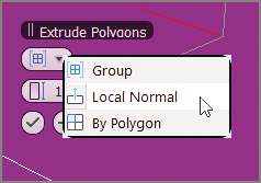
Figure 4-8: Set the extrusion type to Local Normal.
- Set the Height to –0.2, press Enter, and then click the Apply and Continue button (
 ). This will keep the caddy open and allow you to perform another extrusion.
 - Change the Height to 0.3, press Enter, and then click the OK button (
 ) in the caddy.
 - Go to the Edit panel and select Use NURMS. The Use NURMS tab appears in the modeling ribbon (sometimes a floating window will appear instead).
- Turn up the Iterations to 2. The finished product looks pretty good, as shown in Figure 4-9. Now it is time to perform the same piping detail on the seat and back cushions of the couch.
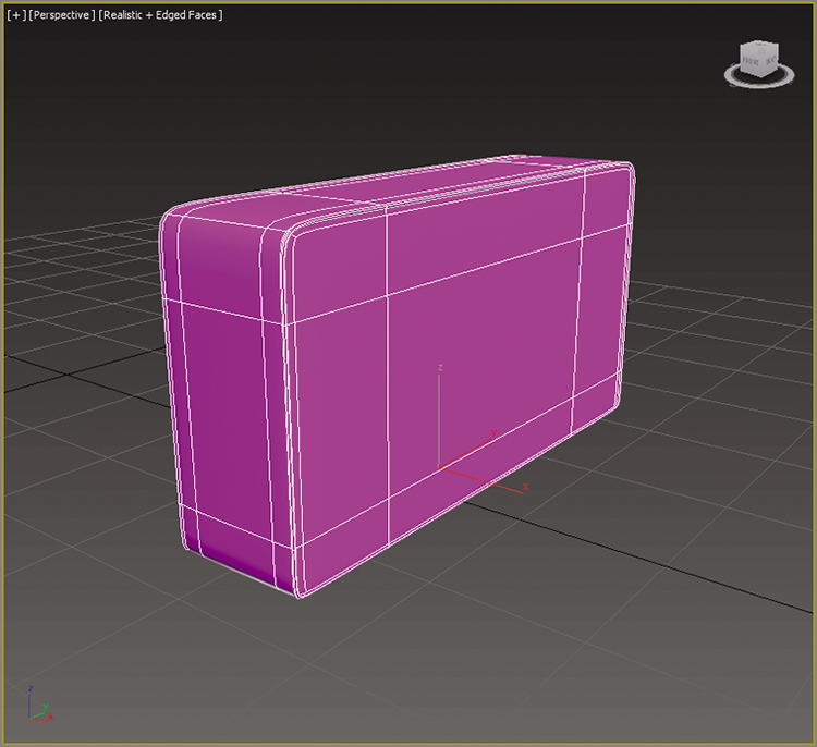
Figure 4-9: The finished couch armrest
- Exit Isolate Selection mode and exit Polygon mode by selecting the Polygon button in the Polygon Modeling tab.
- The seat cushion and three back cushions need to have piping just like the couch arm, so repeat steps 1 through 10 for the cushions.
- The seat base and couch back don’t have any piping, so smooth them using NURMS and the SwiftLoop tool to add edges where needed.
- Select vertices and polygons and move them around to give the surfaces a more random and organic or “lived-in” appearance.
- Save the file, and to check your work open
c04_ex3_detail_end.maxfrom thescenesfolder of thec04_ArchModelproject.
Now is your chance to practice adding the detail to the remaining pieces on the couch. We finished everything but the chaise lounge part of the couch using NURMS with an Iterations level of 2. In the Name And Color rollout we changed the color so the finished pieces would be a consistent color. This is not required to continue with the exercise.
Exercise 4.4: Creating the Chaise Lounge
The chaise lounge isn’t that much different from the rest of the couch. It just has a wing section that comes out from the side, as shown in Figure 4-11. Continue with the file from the previous exercise or open the c04_ex4_chaise_start.max file from the scenes folder of the c04_ArchModel project. Begin by creating the rough chaise cushion.
- Start by choosing Create ⇒ Geometry ⇒ Standard Primitive and create a box. Set the Parameters to Length = 52.0, Width = 24.0, and Height = 8.0. It should be positioned between the left armrest and the seat cushion. Rename the box Chaise Base.
- Convert the box to a polygon (Ribbon ⇒ Modeling tab ⇒ Polygon Modeling ⇒ Convert To Polygon).
- Add a new edge, as shown in Figure 4-10. Use the SwiftLoop tool, and then right-click to release it.
- Enter Polygon mode, and select the polygon on the outside edge of the box.
- In the Ribbon ⇒ Modeling tab ⇒ Polygon tab ⇒ Extrude ⇒ Extrude Settings, enter 10.0 as the Extrude amount, and click OK. Figure 4-11 shows the extruded wing of the chaise.
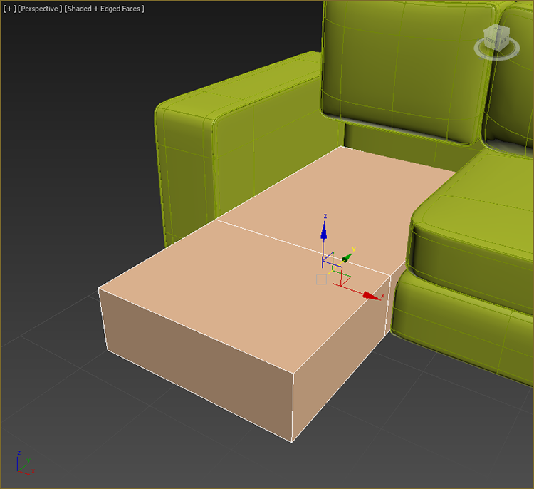
Figure 4-10: Add a new loop to the chaise box.
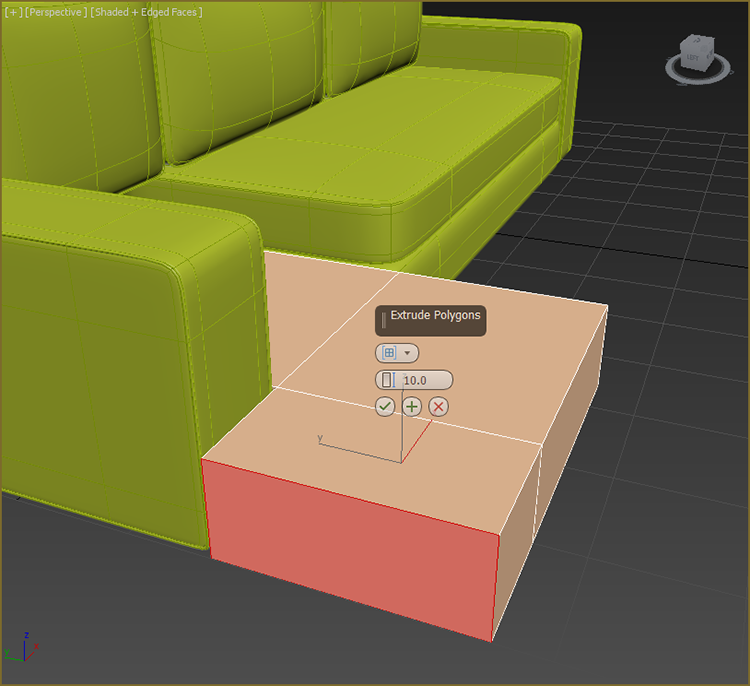
Figure 4-11: Use Extrude to create the wing on the chaise.
- Clone the cushion using the Shift+Move technique, and move the clone upward until it is sitting on top of the cushion. Release the mouse button, in the Clone dialog choose Copy, and rename the clone Chaise Cushion.
- Now that you have completed the chaise lounge section of the couch, you just have to add the finishing touches. Then enter Isolate Selection mode.
- Add new edges using the SwiftLoop tool, matching Figure 4-12.
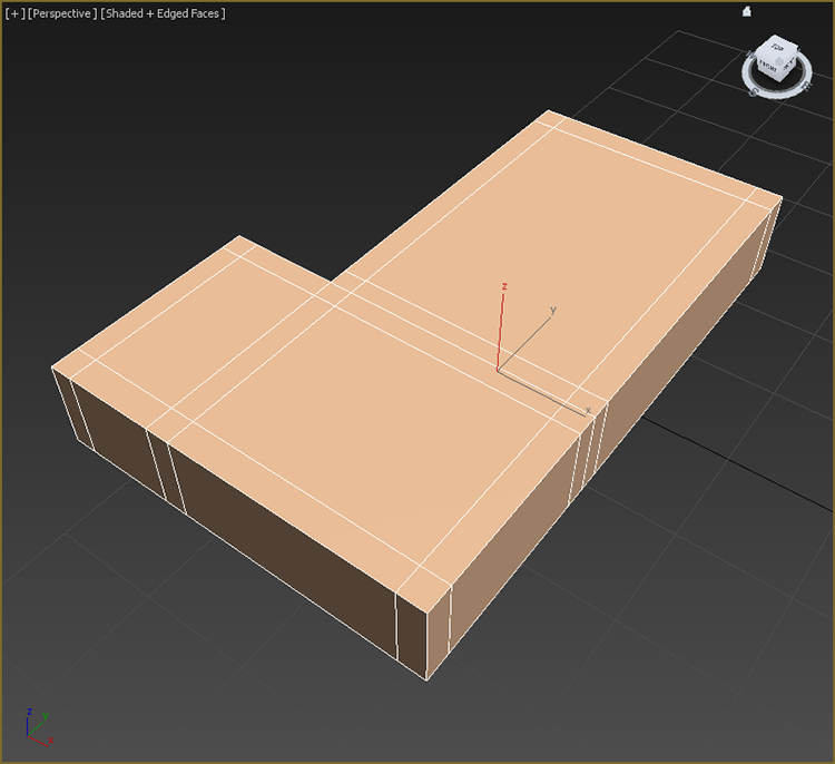
Figure 4-12: Use SwiftLoop to add an edge loop on the chaise cushion box.
- Enter Edge mode, and select the outside edges of the chaise cushion on the top and bottom. Ctrl+click to make multiple selections at once.
- Go to the Edges tab, and open the Chamfer Settings caddy. Change Edge Chamfer Amount to 0.15, press Enter, and then click OK.
- Switch to Polygon mode and select the polygons that were created with the chamfer.
- In the Ribbon ⇒ Modeling tab, go to the Polygons panel and open the Extrude caddy.
- Change the Extrusion type to Local Normal.
- Set the Height to –0.2, press Enter, and then click the Apply and Continue button (
 ). This will keep the caddy open and allow you to perform another extrusion.
 - Change the Height to 0.3, press Enter, and then click OK in the caddy.
- Go to the Edit panel and select Use NURMS. The Use NURMS tab appears in the modeling ribbon (sometimes a floating window will appear instead).
Repeat the same process on the chaise base, except the base has no piping. Save your file, and to check your work open c04_ex4_chaise_end.max from the scenes folder of the c04_ArchModel project.
Exercise 4.5: Modeling the Couch Feet
The final pieces you need to create for the couch are the feet. The feet are all the same, so you just need to create one foot, copy it, and put it in place under the couch. In Figure 4-13, look at the feet and note that they are a box shape that is thinner on the bottom. Continue with the project from the previous exercise or open the c04_ex5_feet_start.max file from the scenes folder of the c04_ArchModel project.
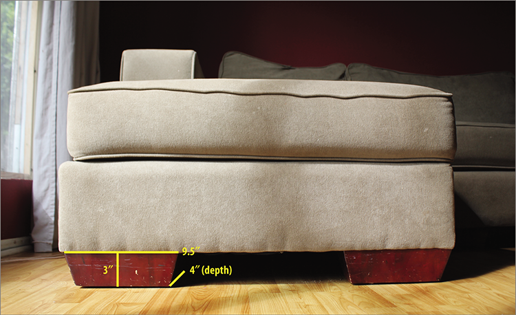
Figure 4-13: The couch feet with measurements
- Go to the command panel’s Create panel, select Geometry, and click Box.
- Click and drag in the Perspective viewport to create a box that will be the first foot.
- Then go to the command panel’s Modify panel, and enter 4.0 for Length, 9.5 for Width, and 3.0 for Height.
- In the Modify panel, click the Modifier List to expand and choose Taper.
- Change Amount to 0.15, as shown in Figure 4-14. Press Enter on your keyboard to set the amount.
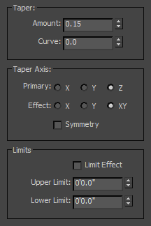
Figure 4-14: The Taper parameters
- Now move the couch foot into place under one of the corners of the couch. Use the clone operation (hold down the Shift key while you move the foot) to make duplicates of the foot and place them around the bottom of the couch at the remaining corners.
- Take the time to select each couch foot box and rename it; use a simple naming convention such as Couch Foot01, 02, 03, and so on.
- Save the file, and to check your work open
c04_ex5_feet_end.maxfrom thescenesfolder of thec04_ArchModelproject.
Now that the couch is finished, as shown in Figure 4-15, it should resemble the original couch but perhaps without the lived-in look and feel the real couch has. You can create some of that look by moving vertices and polygons so that it does not appear quite so perfect.
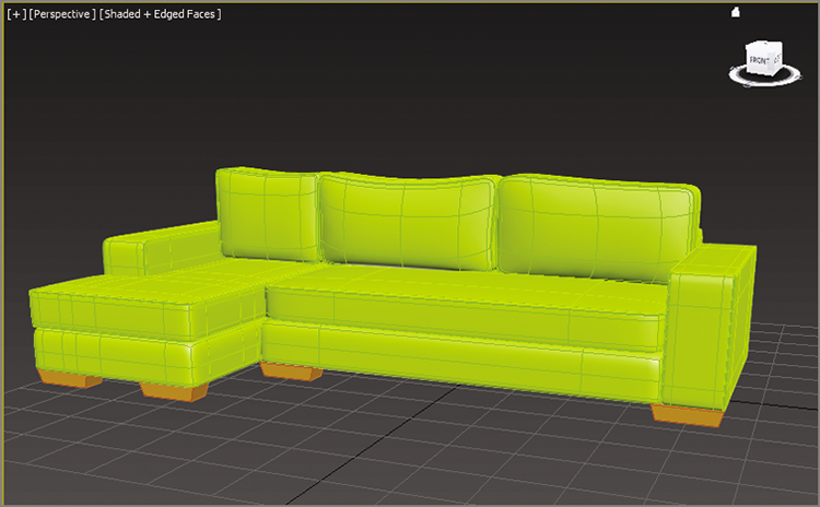
Figure 4-15: The final couch
Modeling the Lounge Chair
To model the chair, you’ll be taking a different approach. You’ll use a spline technique that the software is particularly good at. If you are used to Maya CV curves, the Bezier will seem a bit awkward, but if you are used to Photoshop’s Pen tool, then the 3ds Max Line tools’ way of making lines should be pretty easy. It isn’t just the way you make the lines that makes the 3ds Max tools so nice; it’s also the tools you use to make the lines into 3D objects.
Figure 4-16 shows the chair that will be modeled in this section. Click the Application button and choose Reset from the list that appears. This will set your interface and file back to a startup state.
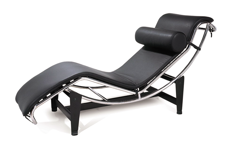
Figure 4-16: The chair for the spline-modeling exercise
Exercise 4.6: Creating Image Planes
This exercise begins with creating planes and applying reference images to them. Set your project to the c04_ArchModel project downloaded to your system. Open c04_ex6_image_start.max. The image with measurements is shown in Figure 4-17.
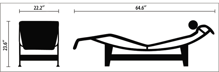
Figure 4-17: The lounge chair with measurements
- In a new scene, go to the Left viewport and create a plane.
- In the Parameters rollout of the command panel, set Length to 23.6 and Width to 64.6.
- Rename this box Lounger_Side View.
- With the plane still selected, go to the Modify tab, and in the Parameters rollout, set Length Segs and Width Segs to 1.
- Then select the Move tool (W) in the main toolbar, and in the Transform Type-In areas at the bottom of the user interface, input 0.0 for X, 0.0 for Y, and 0.0 for Z to place the image at the center of the scene, known as the origin point.
- Repeat steps 1 through 4 with the Front viewport active. The plane parameters are 23.6 for Length and 22.2 for Width.
- Move the plane to these coordinates using the Transform Type-In area: X = –11.0, Y = 32.3, Z = 1.5.
- Rename the plane Lounger_Front View.
- Save the file, and to check your work open the
c04_ex6_image_end.maxfile from thescenesfolder of thec04_ArchModelproject.
Exercise 4.7: Adding the Images
While adding the material to the image planes it’s critical to ensure that the features of the chair that appear in both reference images (the front and the side) are at the same height. For instance, the top of the chair should be at the same height in both the front and side views to make the modeling process easier. Continue with the file from the previous exercise or open the c04_ex7_image_start.max file from the scenes folder of the c04_ArchModel project folder.
- Make sure the Front and Left viewports are set to Shaded.
- Open Windows Explorer and navigate to the
ArchModel/sceneassets/imagesfolder on your hard drive from thec04_ArchModelproject you downloaded from the book’s web page. - Drag
Lounger_Side View.tiffrom the Explorer window to the image plane in the Left viewport. - Drag
Lounger_Front View.tifonto the image plane in the Front viewport. - Save the file, and to check your work open the
c04_ex7_image_end.maxfile from thescenesfolder of thec04_ArchModelproject folder.
The image planes should have the two images mapped on them, as shown in Figure 4-18.
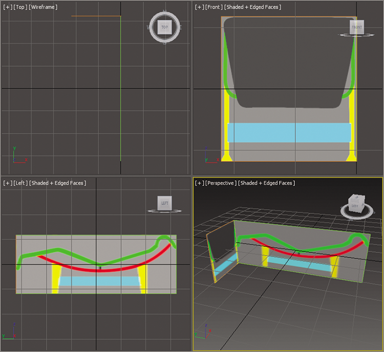
Figure 4-18: Mapped image planes in viewports
Exercise 4.8: Building the Splines for the Chair Frame
Now it’s time to create the splines for the lounge chair. Continue with your own couch file or load c04_ex8_spline_start.max from the scenes folder of the c04_ArchModel project from the book’s web page. The colors added to the images that we used on the planes are to help you build the splines for the lounge chair. To begin, you will build a spline using the green line as a reference.
- Select the Left viewport and then maximize the viewport (Alt+W).
- Go to the command panel and enter Create ⇒ Shapes (
 ), and then select the Line tool. You will use the Line tool to create a spline that follows the side view of the chair. Refer to Figure 4-19; it shows where the vertices should go (corresponding to the numbers in parentheses in the following steps).
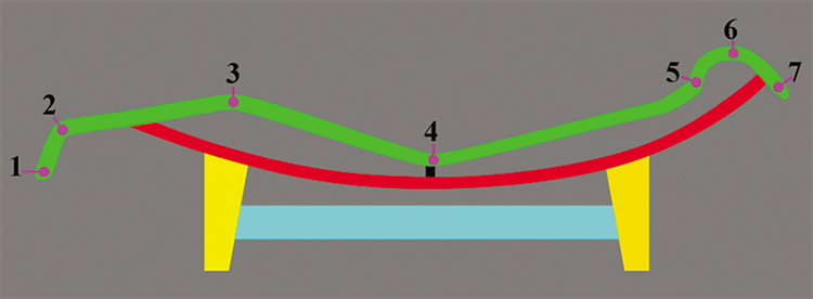
Figure 4-19: Create vertex points by following the numbers.
- Starting at the bottom left of the green line in Figure 4-19, click and release the mouse button to create a corner vertex (1).
- Move your mouse up and to the right; click and release for a corner vertex (2).
- Move to the right; click and release for a corner vertex (3).
- Continue right; click and release for a corner vertex (4).
- Continue right; click and release for a corner vertex (5).
- Drag to make a Bezier curve on the green line (6).
- Right-click and release to create another corner vertex (7), and then right-click to release the Line tool.
- In the Modify panel, select Modifier Stack and enter Vertex mode.
- Select vertex 2 shown in Figure 4-19. In the Geometry rollout, click the Fillet button and drag the vertex until the curve matches the curve in Figure 4-20, an approximate amount of 0.8.
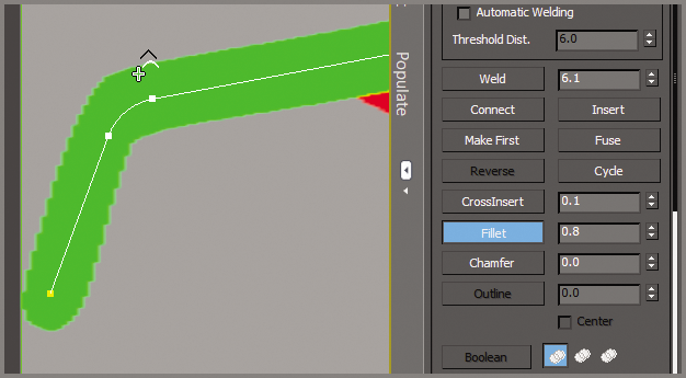
Figure 4-20: A vertex fillet creates two vertices from one and curves the segment between them.
- Repeat the process on vertices 3, 4, and 5. The completed spline is shown in Figure 4-21. Use whatever Fillet value is appropriate for the part of the lounge chair you are working on.
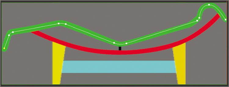
Figure 4-21: The competed spline for the side of the lounge
- When you’ve finished, exit Vertex mode.
- Switch to the Move tool (W) and select the spline.
- Then, in the Front viewport, Shift+Move and align the spline to the frame of the chair on the left side, as shown in Figure 4-22.
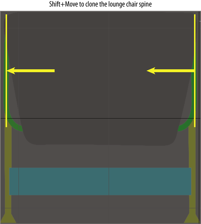
Figure 4-22: Use Shift+Move to clone the chair spline so it lines up with the chair frame on the left.
- When the Clone Options dialog pops up, select Copy and then click OK. Now, these two splines need to be attached to form a single spline. This will allow you to create the bridge piece that runs along the two ends of the frame. Let’s get the image planes out of the way.
- Select both image planes and then right-click to bring up the quad menu. Choose Hide Selection from the Display menu.
- With either spline selected, go to the Geometry rollout, click the Attach button, and then click the other spline, as shown in Figure 4-23.
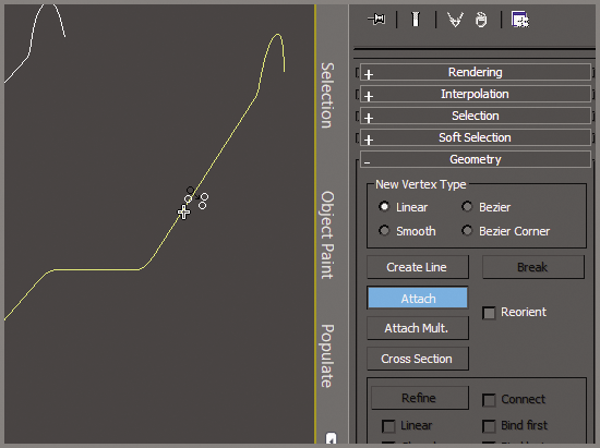
Figure 4-23: Attach both sides of the chair frame.
- Enter Vertex mode. In the Geometry rollout, click the Connect button (below the Weld button).
- Rotate the Perspective viewport so you can see both splines.
- Click and drag from the vertex on the bottom end of the spline to the vertex on the other side, as shown in Figure 4-24. Do the same for the top end of the spline frame.
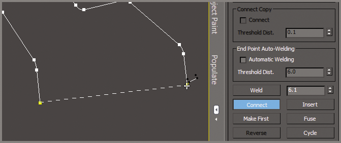
Figure 4-24: Use Connect to create a segment between the two separate splines.
- Right-click to exit from Connect.
- Select the four vertices at the ends of the frame, and in the Geometry rollout, click the Fillet button and move to one of the selected vertices. Drag the vertex until the curve looks appropriate, an amount of about 1.8.
- With the spline selected, go to the Rendering rollout and check the boxes for Enable In Viewport and Enable In Renderer.
- Select Radial and change Thickness to 0.8.
- Click the Render Production button (
 ) in the main toolbar to see the results of the spline rendering, shown in Figure 4-25.
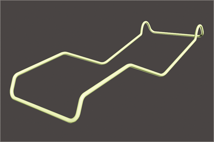
Figure 4-25: The finished lounge frame with spline rendering enabled
You can create the remaining parts of the frame, the arc shape, using the same technique. Continue with your chair file or load c04_ex8_spline_end.max from the scenes folder of the c04_ArchModel project from the book’s web page. This file has the completed seat/back frame, as shown in Figure 4-26.
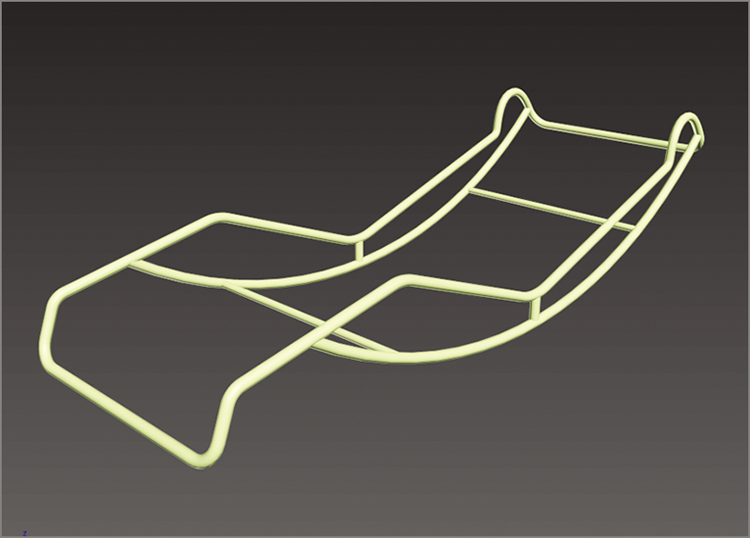
Figure 4-26: The arc frames are attached and connected at the base and top.
Exercise 4.9: Building the Chair Cushion
For the lounge chair cushion, you can’t use the same spline technique you used on the frame. To create it, you have to return to the technique you used for the couch: Create a simple box representation and then use NURMS to soften it. Continue with your own lounge chair file or load c04_ex9_cushion_start.max from the scenes folder of the c04_ArchModel project from the book’s web page.
- Go to the command panel, select Create ⇒ Geometry, and click Box.
- In the Perspective viewport, create a box, and then in the Modify panel, change Length to 64.0, Width to 22.0, and Height to 3.0. Change Length Segs to 4. Move the box so it is over the lounge chair frame.
- In the Ribbon ⇒ Modeling tab, select Polygon Modeling ⇒ Convert To Poly.
- In the Ribbon ⇒ Modeling tab, choose Edit ⇒ SwiftLoop, and add two edge loops close to the ends. These will help you rough out the shape of the lounge cushion.
- Switch to Vertex mode (1); select and move the vertices where the segments are and line them up to follow the chair frame, as shown in Figure 4-27.
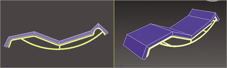
Figure 4-27: Arrange the vertices on the box so they follow the lounge chair frame.
- Use SwiftLoop again, and place edge loops along the left and right edges as well as along the sides. This will keep the outer edges from curving in too much to keep the box shape.
- Go to the Ribbon ⇒ Modeling tab ⇒ Edit ⇒ Use NURMS. In the Use NURMS panel, set Iterations to 2, as shown in Figure 4-29. NURMS has smoothed out the model and molded the lounge-chair cushion to the frame, but it still needs some work.
- Use SwiftLoop to add edge loops, as shown in Figure 4-28. This will help to mold the cushion to the frame.
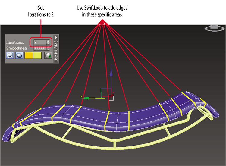
Figure 4-28: Turning up NURMS iterations and using SwiftLoop to smooth out the model
- Save your file; to check your work open
c04_ex9_cushion_end.maxfrom thescenesfolder of thec04_ArchModelproject from the book’s web page.
To finish the cushion, continue adjusting the edges/vertices to create the perfect shape. Also, look at the original reference image in Figure 4-16. There are straps that connect the cushion to the frame. Using the same spline techniques, create the straps to add realism to the overall look. Use the Line tool to create an oval shape that surrounds the frame, and in the Rendering rollout, choose Rectangular (see Figure 4-29).
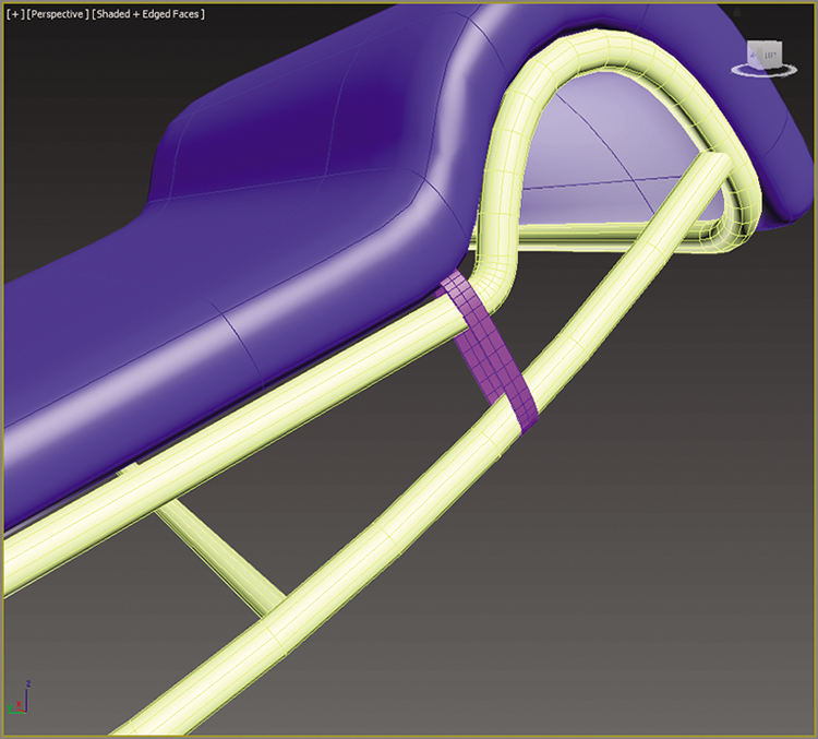
Figure 4-29: Create straps using splines and the Rendering rollout.
Exercise 4.10: Creating the Chair’s Base
The base is made up of the objects on which the frame of the lounge chair sits. There are nine different objects: the four legs, four blocks that sit between the legs, and a block that connects the legs together, as shown in Figure 4-30.
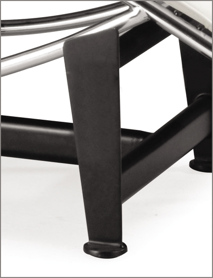
Figure 4-30: The lounge base
Follow these steps to create the lounge base:
- 1. Continue with your chair file or load
c04_ex10_base_start.maxfrom thescenesfolder of thec04_ArchModelproject on the companion web page. - Start by un-hiding the side image plane. Maximize the Left viewport and zoom in so you can see one of the base legs, which are the yellow box shapes.
- Create a box that is the general size of the base leg. The parameters are as follows: Length = 13.2, Width = 4.0, Height = 0.35, Length Segs = 1, Width Segs = 1, and Height Segs = 1.
- Activate See-Through mode (Alt+X) so you can see the image plane through the box primitive, and move the box so it is aligned with the lounge chair frame, as shown in Figure 4-31.
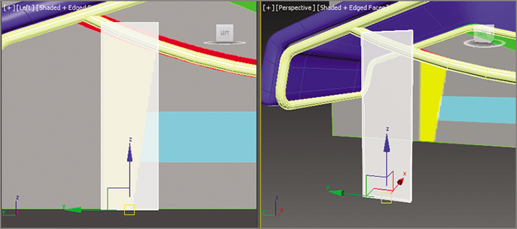
Figure 4-31: Create a box the size of the base leg in the image plane.
- Choose the Ribbon ⇒ Modeling tab ⇒ Polygon Modeling ⇒ Convert To Poly, and enter Vertex mode.
- In the Left viewport, move the vertices so they line up with the yellow box in the image plane, as shown in Figure 4-32.
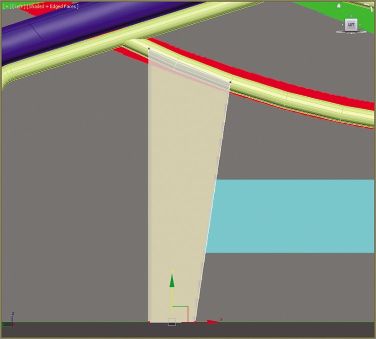
Figure 4-32: Move the vertices so they line up with the image plane.
- Choose the Ribbon ⇒ Modeling tab ⇒ Edit ⇒ SwiftLoop, and add a loop at the bottom. This will set up for adding the foot. Right-click to exit SwiftLoop.
- Switch to a Perspective viewport and rotate the viewport so you can see an angled view.
- Enter Polygon mode, and select the polygons between the new edge loop and the bottom of the Leg object. Exit See-Through mode (Alt+X).
- Choose the Ribbon ⇒ Modeling tab ⇒ Polygons ⇒ Extrude ⇒ Extrude Settings. In the caddy, change the extrusion type to Local Normal and change the Height to 1.6. Press Enter to set the input; then click the OK button in the caddy, as shown in Figure 4-33.
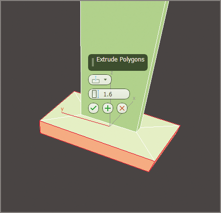
Figure 4-33: Use Extrude to begin the creation of the foot.
- Choose the Ribbon ⇒ Modeling tab ⇒ Edit ⇒ SwiftLoop, and add edge loops, as shown in Figure 4-34, with edged faces turned on for better visibility.
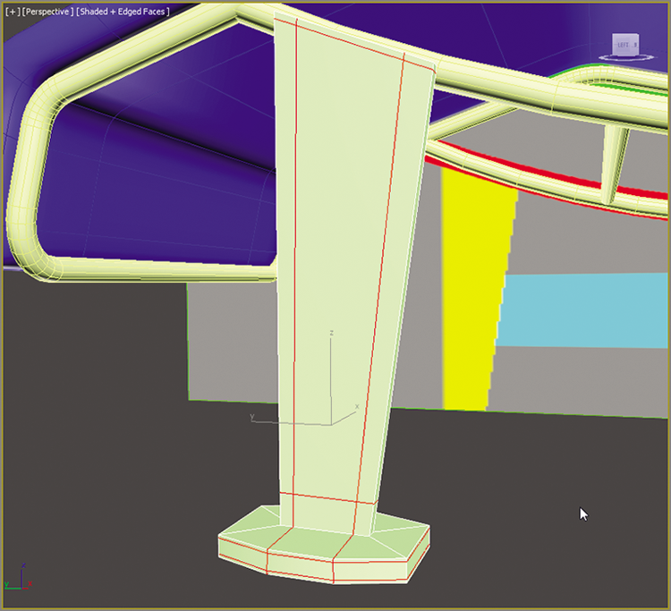
Figure 4-34: Add edge loops using SwiftLoop in designated areas.
- Choose the Ribbon ⇒ Modeling tab ⇒ Edit and turn on Use NURMS.
- This looks very good, but you’ll need to move vertices and/or edges to refine the shape of the object to match the leg shown in Figure 4-30.
- When the leg is finished, copy it three times and position the copies so they are aligned with the frame (use Figure 4-16 as a reference for the position of the legs).
- Create the remaining pieces using the same techniques you used to create the leg.
- Save the file. To check your work open
c04_ex10_base_end.maxfrom thescenesfolder of thec04_ArchModelproject on the companion web page.
The final result is shown with appropriate colors applied (default colors) in Figure 4-35.
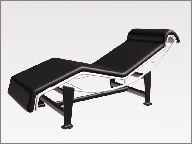
Figure 4-35: The final base shown with frame and cushion
Bringing It All Together
Now that the furniture is built, it’s time to furnish the room you built in Chapter 3. You can do this by merging the furniture 3ds Max files into the room file. Merge allows you to load objects from one 3ds Max file into your current file. Open the c03_room_final.max file from the c03_ArchModel project folder. Or use the file that you completed in Chapter 3. Then follow these steps:
- In the
c03_room_final.maxproject file, click the Application button ( ) and select Import ⇒ Merge.
 - When the Merge File dialog box opens, navigate to the
c04_ArchModelproject folder, select thec04_Couch_Final.maxfile or use your own file, and click Open. The Merge dialog box will open, and you will see a list of objects available to merge from that file. - At the bottom of the dialog box, select All, as shown in Figure 4-36, and click OK. If you use your own files, the names may be different than those in the figure.
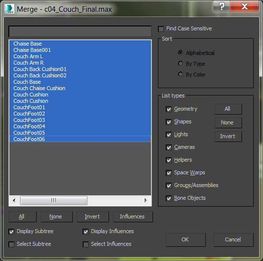
Figure 4-36: In the Merge dialog box, select the All button at the bottom of the dialog.
- Click the Zoom Extends All Selected button located at the lower-right corner of the interface; it is a flyout, which means there are more buttons under Zoom Extends All; this will zoom in on the already selected Couch objects.
- Go to the Group menu and select Group. Name the group Couch and click OK.
- Position the couch in the room.
- Check the images of the room for couch location (see reference Figure 4-1 from the beginning of the chapter). Check the Front and Left viewports to make sure the couch is level with the floor.
- Repeat steps 1 through 7 to merge in and place the spline chair using the file
c04_LoungeChair_Final.max.
These two pieces of furniture look great, but they don’t fill up the room. To help furnish your newly built room, you can merge some prebuilt items into the space. Repeat steps 1 through 7 for the extra furniture pieces, which can be found in the Chapter 04 Extra Furniture folder in the scenes folder of the c04_ArchModel project. The room will look better after you merge the objects. The next phase for you may be to create some of your own objects to populate the room.