Chapter 14
3ds Max Rendering
Rendering is the last step in creating your CG work, but it is the first step to consider when you start to build a scene. During rendering, the computer calculates the scene’s surface properties, lighting, shadows, and object movement and then saves a sequence of images. To get to the point where the computer takes over, you’ll need to set up your camera and render settings so that you’ll get exactly what you need from your scene.
This chapter will show you how to render your scene using the Scanline Renderer in the Autodesk® 3ds Max® software and how to create reflections and refractions using raytracing.
In this chapter, you’ll learn to:
- Navigate the Render Setup dialog
- Render a scene
- Work with cameras
- Raytrace reflections and refractions
- Render the interior and furniture
Navigate the Render Setup Dialog
Your render settings and the final decisions you make about your 3ds Max scene ultimately determine how your work will look. If you create models and textures with the final image in mind and gear the lighting toward elegantly showing off the scene, the final touches will be relatively easy to set up.
The Render Setup dialog box is where you define your 3ds Max render output. You can open this dialog box by taking one of the following actions:
- Click the Render Setup icon (
 ) in the main toolbar.
 - Select Rendering ⇒ Render ⇒ Render Setup.
- Press F10.
You’ve already seen how to render (![]() ) a frame in your scene to check your work. The settings in the Render Setup dialog box are used even when the Render Production button is invoked, so it’s important to understand how this dialog box works.
) a frame in your scene to check your work. The settings in the Render Setup dialog box are used even when the Render Production button is invoked, so it’s important to understand how this dialog box works.
Common Tab
The Render Setup dialog box is divided into five tabs; each tab has settings grouped by function. The Common tab stores the settings for the overall needs of the render—for example, image size, frame range to render, and type of renderer to use. Some of the most necessary render settings are described here:
- Time Output In this section, you can set the frame range of your render output by selecting one of the following options:
- Single Renders the current frame only
- Active Time Segment Renders the current range of frames
- Range Renders the frames specified
- Output Size The image size of your render, which is set in the Output Size section, will depend on your output format—that is, how you want to show your render.
- Resolution By default, the dialog box is set to render images at a resolution of 640×480 pixels, defined by the Width and Height parameters, respectively.
- Image Aspect Changing the Image Aspect value will adjust the size of your image along the Height parameter to correspond with the existing Width parameter. For example, regular television is 1.33:1 (simply called 1.33) and a high-definition (HD) television is a wide screen with a ratio of 1.78:1 (simply called 1.78). The resolution of your output will define the screen ratio.
- In the Output Size section of the Render Setup dialog box, there is a drop-down menu for choosing presets from different film and video resolutions. The image quality and resolution of a render affect how long a render will take.
- Options The Options section lets you access several global toggles. You can toggle the rendering of specific elements in your scene. For example, if you are using atmospherics (volume light) or effects (lens flare) and don’t want them to render, you can clear the appropriate boxes.
- Render Output Use the Render Output section to indicate that the file should be saved. The image format can be selected to be a single image file or a sequence of image files (such as Targa or TIFF files) that form a sequence, or it can be a movie file such as QuickTime.
Choosing a Filename
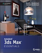
To specify a location and file type for the render, click the Files button in the Render Output section. This will open the Render Output File dialog box shown in Figure 14-1. Select the folder to which you want to render, and set the filename. You can set the file type using the Save As Type drop-down menu.
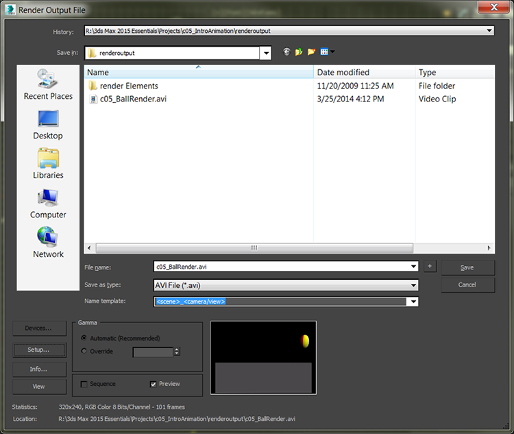
Figure 14-1: The Render Output File dialog box defines how the render saves to disk.
Rendered Frame Window
When you click the Render button at the bottom of the Render Setup dialog box, the Rendered Frame window opens, shown in Figure 14-2.
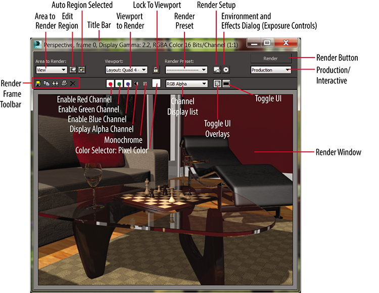
Figure 14-2: The Rendered Frame window
The Rendered Frame window shows you how the frames look as the renderer processes through the sequence of frames. A collection of quick-access buttons on the frame is also available in the Render Frame window.
Render Processing
When you click Render, a rendering progress dialog shows what parameters are being used for a scene and a progressing bar, shown in Figure 14-3. This dialog box shows the parameters being used, and it displays a progress bar indicating the render’s progress. You can pause or cancel the render by clicking the appropriate button.
Figure 14-3: The Rendering processing dialog shows you everything you want to know about your current render.
Assign Renderer
Five types of renderers are available by default (without any additional plug-ins installed). The Default Scanline Renderer is the default renderer. It is already assigned and appears in the Assign Renderer rollout. To access the Choose Renderer dialog box click the ellipsis button (![]() ). Only four renderers appear because the Default Scanline Renderer is already assigned. mental ray rendering is covered in Chapter 15, “mental ray.”
). Only four renderers appear because the Default Scanline Renderer is already assigned. mental ray rendering is covered in Chapter 15, “mental ray.”
Render a Scene
3D rendering is the 3D computer graphics process of automatically converting 3D wireframe models into 2D images with 3D photorealistic effects or non-photorealistic rendering on a computer.
Exercise 14.1: Rendering the Bouncing Ball
Seeing is believing, but doing is understanding. In this exercise, you will render the bouncing ball animation from Chapter 5, “Introduction to Animation,” to get a feel for rendering an animation using the 3ds Max program. Just follow these steps:
- Set your project folder to the c14_Rendering project that you downloaded to your hard drive from the companion web page at www.sybex.com/go/3dsmax2015essentials.
- Open the
c14_ex1_render.maxfile in thescenesfolder. If a File Load: Gamma & LUT Settings Mismatch dialog shows up, select Adopt The File’s Gamma And LUT Settings? and then select OK. Now, let’s render a movie to see the animation. - Open the Render Setup dialog box (
 ), and in the Time Output section, select Active Time Segment: 0 To 100.
 - In the Output Size section, select the 320×240 preset button and leave Image Aspect and Pixel Aspect as is.
- Leave the Options group at the defaults, and skip down to the Render Output section.
- Click the Files button to open the Render Output File dialog box, and navigate to where you want to save the output file, preferably into the
renderoutputfolder in yourc14_Renderingproject. - Name the file
c14_ex1_render, and click the drop-down menu next to Save As Type to choose MOV QuickTime File (*.mov) for your render file type. - After you select MOV QuickTime File and click the Save button, the Compression Settings dialog box, shown in Figure 14-4, opens.
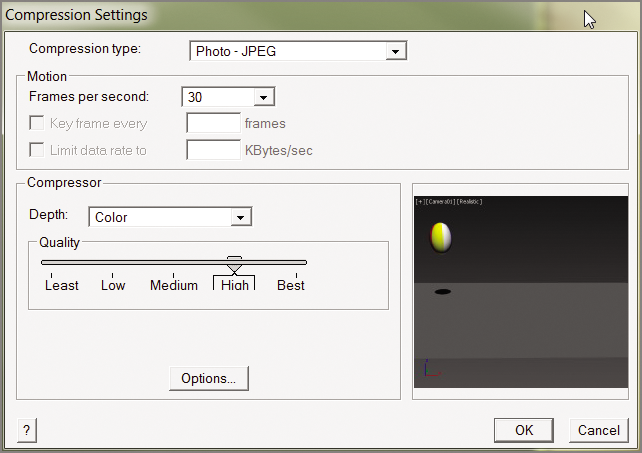
Figure 14-4: QuickTime compression settings affect the quality of the rendered QuickTime video file.
- Set the parameters for the QuickTime file as indicated:
- Compression Type: Photo - JPEG
- Frames Per Second: 30
- Compressor Depth: Color
- Quality: High
- Click OK to close the Compression Settings dialog box
- Select the viewport you want to render in the View drop-down menu. You need to render Quad 4 - Camera01.
- Click Render.
- After the render is complete, navigate to your render location (by default, it is set to the
renderoutputfolder for the c14_Rendering project). - Double-click the QuickTime file to see your movie.
To see an already rendered QuickTime movie of the ball animation and to check your work, navigate to your render location; it is set to the renderoutput folder for the c14_Rendering project.
Work with Cameras
The 3ds Max cameras, as shown in the Perspective viewport in Figure 14-5, capture and output all the fun in your scene. In theory, 3ds Max cameras work as much like real cameras as possible.
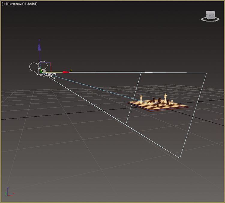
Figure 14-5: A camera as seen in the Perspective viewport
The camera creates a window through which you can see and render your scene. You can have as many cameras in the scene as you want. You can use the Perspective viewport to move around your scene as you work, leaving the render camera alone.
There are two types of 3ds Max cameras:
- Target Camera A target camera, much like a target spotlight, has a Target node that allows it to look at a spot defined by where the target is placed (or animated). A target camera is easier to aim than a free camera because once you position the Target object at the center of interest, the camera will always aim there.
- Free Camera On the other hand, free cameras have only one node, so they must be rotated to aim at the subject, much like a free spotlight. If your scene requires the camera to follow an action, you will be better off with a target camera.
- You can create a camera by clicking the Cameras icon (
 ) in the Create panel and selecting either of the two camera types:
- To create a free camera, click in a viewport to place it.
- To create a target camera, click in a viewport to lay down the Camera node, and then drag to pull out and place the Target node.
A camera’s main feature is the lens, which sets the focal length in millimeters and also sets the field of view (FOV), which determines how wide an area the camera sees, in degrees. By default, a 3ds Max camera lens is 43.456mm long with an FOV of 45 degrees. To change a lens, you can change the Lens or FOV parameters, or you can pick from the stock lenses available for a camera in its Modify panel parameters, as shown in Figure 14-6.
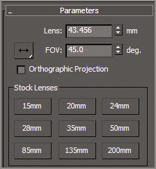
Figure 14-6: Stock lenses make it easy to pick the right lens for a scene.
The most interactive way to adjust a camera is to use the viewport navigation tools. The Camera viewport must be selected for the viewport camera tools to be available to you in the lower-right corner of the user interface (UI). You can move the camera or change the lens or FOV.
Exercise 14.2: Creating a Camera
The best way to explain how to use a camera is to create one. Set your project to the c14_Rendering project you have downloaded to your hard drive from this book’s web page. Open the c14_ex2_cameras_start.max scene file in the scenes folder.
- In the Create panel, click the Cameras icon (
 ), select the target camera, and go to the Top viewport. Click from the window inside the room and drag toward the gap between the coffee table and the couch. The camera is created along the ground plane. You need to move the entire camera up.
- You will need to exit the Create panel and right-click in the Top viewport. Select both the camera and the target to move them as a unit by clicking the line that connects the camera and target in the viewport, and then in the Front viewport use the Move tool to relocate the camera higher in the scene.
- To see the Camera viewport, select a viewport and press the C key. This changes the viewport to whatever camera is currently selected. In Figure 14-7 you can see Camera001 in all viewports.
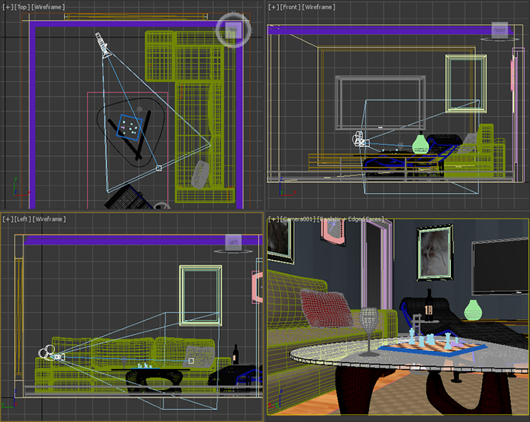
Figure 14-7: The camera shown in the Top, Front, Left, and Camera001 viewports.
- Now render the scene—press F9 or click the teapot icon (
 ) in the main toolbar—through the camera you just created and positioned.
Now that the camera is set up, take some time to move it around and see the changes in the viewport. To move the camera, select the Camera object. Use the Move tool. Moving a camera from side to side is known as a truck. Moving a camera in and out is called a dolly. Rotating a camera is called a roll. Also change the Lens and FOV settings to see the results. Save the file, and to check your work open the c14_ex2_cameras_end.max file in the c14_Rendering project folder.
Exercise 14.3: Animating a Camera
Camera animation is done in the same way as animating any object. You can animate the camera, the target, or both. You can also animate camera parameters such as Lens or FOV. Open the c14_ex3_animate_start.max scene file in the scenes folder in the c14_Rendering project folder.
- Select the camera.
- Move the time slider to frame 60.
- Press the N key to activate Auto Key, or click its button.
- In the Top viewport, use the Move tool to move the camera farther away from the chess set; watch the Camera001 viewport to be sure you don’t go outside the room. The direction or distance doesn’t really matter just as long as it is different than the previous camera position.
- Look in the Camera001 viewport, and then move the time slider through the animation. Press the N key again to turn off Auto Key. The camera should just move away from the chess set parallel to the window, as shown in Figure 14-8. Don’t worry if your camera position isn’t the same as in the figure.
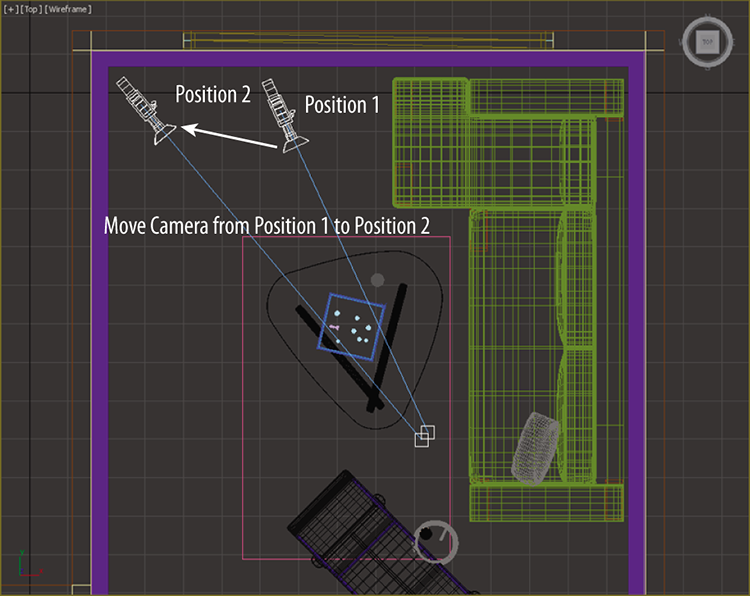
Figure 14-8: Move the camera in the Top viewport.
Save the file, and to check your work open the c14_ex3_animate_end.max file in the c14_Rendering project folder.
Clipping Planes
In a huge scene, you can exclude, or clip, the geometry that is beyond a certain distance from the camera by using clipping planes. This helps minimize the amount of geometry that needs to be calculated. Each camera has a clipping plane for distance (Far Clip), as shown in the left image in Figure 14-9, and for the foreground (Near Clip), as shown in the right image. The near clipping plane clips geometry within the distance designated from the camera lens.
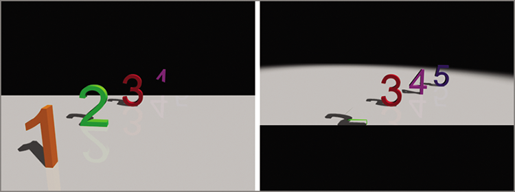
Figure 14-9: A far clipping plane cuts off the distant extents of a scene (left). A near clipping plane cuts off the extents directly in front of a camera (right).
To enable clipping planes, click the Clip Manually check box and set the distances needed. Once you turn on manual clipping planes, the camera displays the near and far extents in the non-camera viewports with red plane markers.
Exercise 14.4: Safe Frames
Safe Frames allow you to see the portions of your rendered output within a viewport. Safe Frames display a series of rectangular frames in the viewport. This is particularly useful when you are rendering to output that doesn’t match the viewport’s aspect ratio. Open the c14_ex4_safe_start.max scene file in the scenes folder in the c14_Rendering project folder.
- In the Camera001 viewport, click the General Viewport Label menu (
 ) and choose Configure Viewports near the bottom of the menu.
 - In the dialog box, choose the Safe Frames tab. This tab contains settings for frame types, as shown in Figure 14-10.
Figure 14-10: The Safe Frames tab in the Viewport Configuration dialog box
- The default is to show only the Live Area Safe Frame. To have the other Safe Frames show, you check the boxes in the Safe Frames tab.
The Live Area Safe Frame is the extent of what will be rendered. The Action Safe area is the boundary where you should be assured that the action in the scene will display on most if not all TV screens. The Title Safe area is where you can feel comfortable rendering titles in your frame. Finally, the User Safe setting is for setting custom frames, as shown in Figure 14-11.
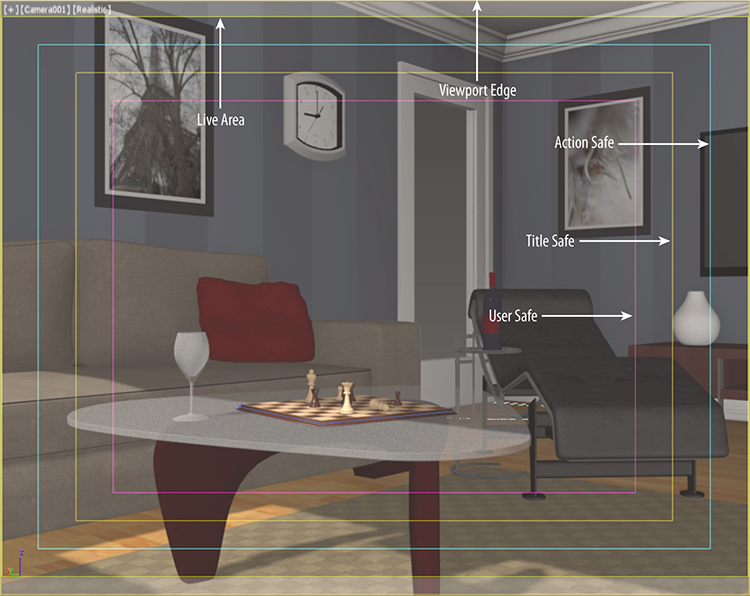
Figure 14-11: Safe Frames shown in the Camera001 viewport
Save the file, and to check your work open the c14_ex4_safe_end.max file in the c14_Rendering project folder.
Raytraced Reflections and Refractions
As you saw in Chapter 9, “Introduction to Materials,” you can apply a Raytrace map to a material’s Reflection parameter to add a reflection to the object. To get a true reflection of the other objects in the scene, you will need to use the raytracing methodology. There are essentially two ways to create raytraced reflections in a scene:
- By using a Raytrace map
- By using a Raytrace material
In many cases, the Raytrace map looks great and saves tons of rendering time as opposed to using the Raytrace material.
Exercise 14.5: Raytrace Material
In the following steps, you will learn how to use the Raytrace material to create reflection in a scene using the room built in Chapter 3 and Chapter 4. Open the c14_ex5_raytrace_start.max scene file in the scenes folder in the c14_Rendering project folder.
- Open the Material Parameter Editor; in the Material/Map Browser, select Materials ⇒ Standard and drag Raytrace material into the active view.
- Double-click on the node title area to load the parameters into the Material Parameter Editor, and change the material name to NewDark Wood.
- The parameters to create reflections are available through the Raytrace Basic Parameters rollout. Leave most of these parameters at their default values, but change the Reflect color swatch from black to white. This sets the reflection of the material all the way to the maximum reflectivity.
- In the Material/Map Browser, choose Maps ⇒ Standard and drag Bitmap to the Diffuse input socket of the Raytrace material. This will bring up the Select Bitmap Image File dialog box; you should see the
imagesfolder of thec14_Renderingproject folder. - Choose
DarkWood_Grain.jpgand then click Open. - Apply the New Dark Wood Raytrace material to the coffee table legs in the scene. Render the Camera001 viewport. The coffee table leg is very reflective; it looks like a mirror, as shown in Figure 14-12.
- Go back to the Raytrace Basic Parameters rollout, select the color swatch next to Reflect, and change the Reflect color (RGB sliders only) so that R = 20, G = 20, and B = 20, which is a darker gray and will lessen the reflections.
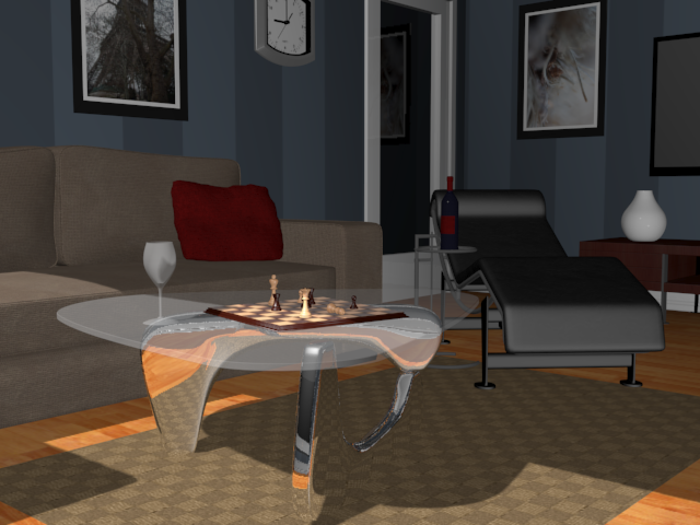
Figure 14-12: The Raytrace material with reflections set to the maximum
- In the Specular Highlight area, change Specular Level to 80 and Glossiness to 70. This will change how clear the reflection appears.
- Go to the Raytracer Controls rollout, and in the Falloff End Distance area check the box next to Reflect and change the value to 50. This parameter will fade the reflection over distance, which is more accurate. Select the Camera001 and render, as shown in Figure 14-13.
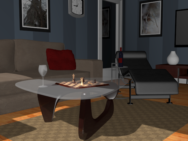
Figure 14-13: More accurate reflections are added to the coffee table legs.
Save the file. To check your work open the c14_ex5_raytrace_end.max file in the c14_Rendering project folder.
Exercise 14.6: Raytrace Mapping
You use Raytrace map as you do other maps. This means you can add raytraced reflections or refractions to any kind of material. In this case, you will assign a Raytrace map to the Reflection map channel of a material to get truer reflections in the scene and at a faster render time than when using the material as you just did. Continue with your file or open the c14_ex6_raytrace_start.max scene file in the scenes folder in the c14_Rendering project folder.
- In the Material Parameter Editor and in the Material/Map Browser, select Materials ⇒ Standard and drag a Standard material to the view area. Load the materials into the Material Parameter Editor and change the name to Hardwood Floors.
- In the Material/Map Browser, choose Maps ⇒ Standard and drag a Raytrace map into the Reflection input socket.
- In the Material/Map Browser, choose Maps and drag a Bitmap map into the Diffuse Color input socket.
- From the Select Bitmap Image File dialog box, choose
Hardwood_honey.tiffrom theimagesfolder. - In the Maps rollout, change Reflection Amount to 50.
- Apply the Hardwood Floors material to the Floor object in the scene by dragging from the output socket to the Floor object in the Camera001 viewport.
- In the Material Parameter Editor toolbar, select the Show Shaded Material in Viewport button (
 ).
). - Render the Camera001 viewport; the floors look good but too reflective, and a falloff needs to be added.
- Double-click the Raytrace Map node to load the parameters into the editor.
- In the Attenuation rollout, change Falloff Type to Linear, and then change Ranges: End to 50. Render the Camera001 viewport; the results are shown in Figure 14-14.
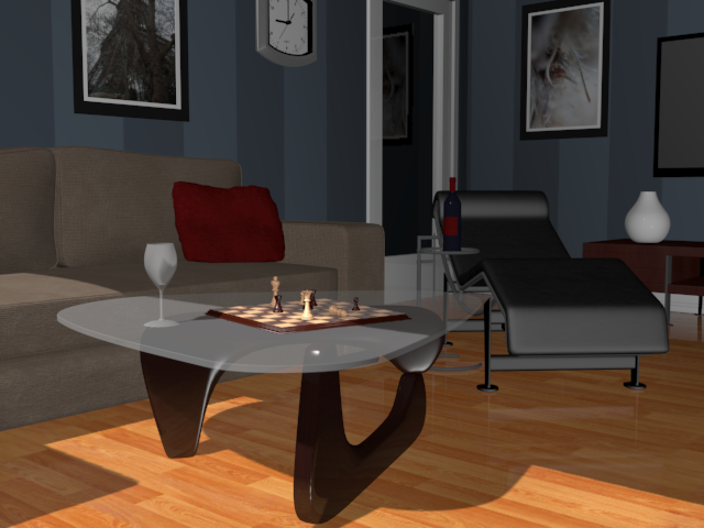
Figure 14-14: The reflection map with falloff
Take a look at the images created with reflections using the Raytrace material and those created using the Standard material with the Raytrace map applied to reflection. They look almost the same. However, there is slightly better detail in the reflections created with the Raytrace material but with longer render times. Save the file. To check your work open the c14_ex6_raytrace_end.max file in the c14_Rendering project folder.
Exercise 14.7: Refractions Using the Raytrace Material
Creating raytraced refractions in glass can be accomplished using the same two workflows, as for the raytraced reflections from the previous sections. The Raytrace material renders better, but it takes longer than using a Raytrace map for the refraction map in a material. Continue with your file or open the c14_ex7_raytrace_start.max scene file in the scenes folder in the c14_Rendering project folder. This file has a rug in it.
- For this section you are going to create a new camera. Start by changing the Camera001 viewport to a Perspective viewport:
- Select the Camera001 viewport and press P on the keyboard.
- Select the wineglass in the scene and then press Z on your keyboard. This will frame the wineglass in the Perspective viewport.
- c. Use Ctrl+C, which is a shortcut, to create a camera from a Perspective viewport.
- Name the camera Wine Glass Camera.
- In the Material Parameter Editor, drag a Raytrace material from the Material/Map Browser into the area. Name it Wine Glass, and apply the material to the wineglass.
- Go to the Raytrace Basic Parameters rollout, and change the color swatch for Transparency from black to white.
- Uncheck the box next to Reflect and change that spinner to 10. This sets a slight reflection for the material.
- Take a look at the Index Of Refr parameter. This value sets the index of refraction (IOR) value that determines how much the material should refract. The value is already set to 1.55. Leave it at that value.
- Go to the Extended Parameters rollout, shown in Figure 14-15. The Reflections section is at the bottom.

Figure 14-15: The Extended Parameters rollout for the Raytrace material
- Select Additive and change Gain to 0.7. This gives a bit of reflective brightness for the clear wineglass.
- Render the Wine Glass Camera viewport. The render shows the Raytrace material on the wineglass refracting and reflecting, but you may notice the jagged edges or artifacts around the reflected objects. What you’re seeing is aliasing in the reflections.
- Clone this rendered image by pressing the Clone Rendered Frame Window icon (
 ), which is found in the Rendered Frame Window toolbar. This allows you to compare the before and after shots of the rendering.
- Go to the SuperSampling rollout and uncheck Use Global Settings.
- Check Enable Local Supersampler and keep it set to Max 2.5 Star. Leave the other parameters at their defaults, as shown in Figure 14-16. Render the Wine Glass Camera viewport.

Figure 14-16: The SuperSampling rollout
- In the Specular Highlight group, change Specular Level to 98 and Glossiness to 90. Figure 14-17 shows these changes.
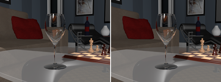
Figure 14-17: The wineglass with default SuperSampling (left); the SuperSampling modified (right)
- Render the Wine Glass Camera viewport.
You will see a very nice wineglass render. Change the Index of Refr parameter on the material to 8.0 and you will see a much greater refraction, as shown in Figure 14-18. That may work better for a heavy bottle, but it is too much for the glass. An Index Of Refr parameter between 1.5 and 2.5 works pretty well for the wineglass.
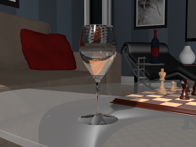
Figure 14-18: A much more pronounced refraction is rendered with an IOR of 8.0.
Save the file. To check your work open the c14_ex7_raytrace_end.max file in the c14_Rendering project folder.
Exercise 14.8: Refractions Using Raytrace Mapping
Just as you did with the reflections, you will now use a Raytrace map on the Refraction parameter for the Wine Glass material. Open the c14_ex8_raytrace_start.max scene file in the scenes folder in the c14_Rendering project folder.
- In the Material Parameter Editor, drag a Standard material from the Material/Map Browser into the view area. Name it Wine Glass 1.
- Drag the Raytrace map from the Material/Map Browser into the Refraction input slot.
- Drag the Raytrace map from the Material/Map Browser into the Reflection input slot.
- Go to the Maps rollout and change Reflection Amount to 6. This will reduce the amount of reflection.
- Go to the SuperSampling rollout and uncheck Use Global Settings, check Enable Local Supersampler, and keep it as Max 2.5 Star.
- In the Specular Highlights group, change Specular Level to 98 and Glossiness to 90.
- Apply the material to the Wine Glass object in the scene and render as shown in Figure 14-19. In the Raytrace map, you can control the IOR through the material parameters in the Extended Parameters rollout, in the Advanced Transparency section, as shown in Figure 14-20.
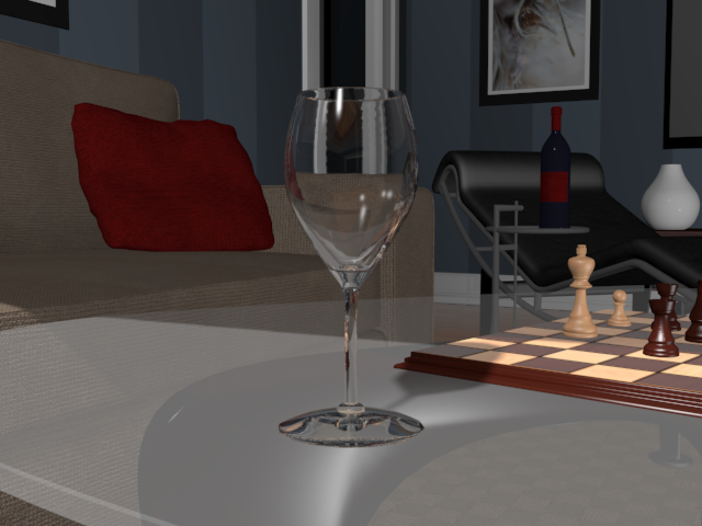
Figure 14-19: Use the Raytrace map on the Refraction parameter to create refraction in the wineglass.
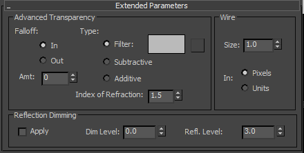
Figure 14-20: The Advanced Transparency section in the Extended Parameters rollout
The raytracing reflections and refractions slow down the render quite a bit. You can leave out the reflections if you’d like, but that will reduce the realistic look of the wineglass. Save the file. To check your work open the c14_ex8_raytrace_end.max file in the c14_Rendering project folder.
Render the Interior and Furniture
The Raytrace map calculates reflections as they work in the real world, reflecting the object’s environment. Let’s take a quick look at rendering the short 30-frame sequence of the scene you did earlier in the chapter. You’ll need to tweak a few of the scene settings, such as setting the furniture and the interior materials to have raytraced reflections for maximum impact. Let’s go!
Exercise 14.9: Adding Raytraced Reflections
Open the c14_ex9_raytrace_start.max scene file in the scenes folder in the c14_Rendering project folder.
- In the Slate Material Editor, at the bottom left of the view area, is an icon of a pair of binoculars. This is a search feature. Click it, and a type-in area appears.
- Then type Light Wood for Chess in the type-in area and press Enter. The material will be zoomed in on the active view, as shown in Figure 14-21.
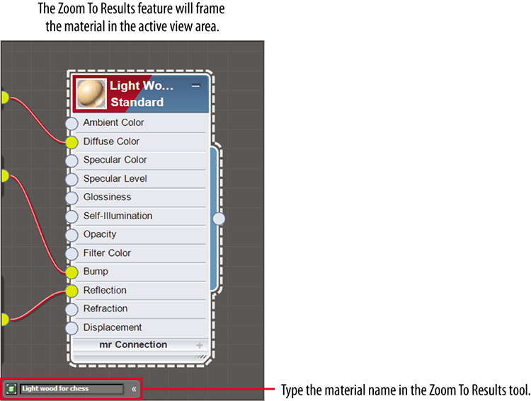
Figure 14-21: Frame the material using the Zoom To Results feature in the Material Parameter Editor.
- In the Material/Map Browser, select Maps ⇒ Standard, drag a Raytrace map into the area, and then drag from the output socket of the Raytrace map into the input socket of the reflection map, as shown in Figure 14-22.
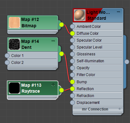
Figure 14-22: Plug the Raytrace map into the Reflection input socket of the Light Wood for Chess material.
- Double-click the title of the Light Wood for Chess material to load the parameters into the Material Parameter Editor, and in the Maps rollout, change the Amount value for Reflection to 20.
- Render a frame, and you should see some reflections of the room.
- Go through the materials in the Material Parameter Editor to add a Raytrace map to the material’s Reflection channels.
Save the file. To check your work, open the c14_ex9_raytrace_end.max file in the c14_Rendering project folder.
Exercise 14.10: Outputting the Render
You need to render out the entire 30 frames of the camera move. As you saw with the bouncing ball render earlier in the chapter, rendering out a sequence of images is done through the Common tab of the Render Setup dialog box. Open the c14_ex10_raytrace_start.max scene file in the scenes folder in the c14_Rendering project folder.
- In the Time Output section, click to select Range and change it to read 0 to 60, as shown in Figure 14-23.
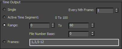
Figure 14-23: The Time Output section setup for a range from 0 to 60
The resolution of the render is set in Output Size. The default resolution is 640×480.
- Go to the Render Output section of the Render Setup dialog box and click Files to open the Render Output File dialog box. Typically, animations are rendered out as a sequence of images, but for simplicity’s sake, you will render it out to an AVI.
- In the Render Output File dialog box, choose where you want to store the rendered file and pick a name for the movie (
Room_Raytrace.avi, for example). - Then, in the Save As Type drop-down menu, choose AVI File (*.avi) and click Save. The AVI File Compression Setup dialog box will appear.
- In the AVI File Compression Setup dialog box, select MJPEG Compressor for the compressor type, and set the Quality slider to 100. This Quality setting applies only to the compression of the AVI file and not to the render itself.
- Click OK to return to the Render Output File dialog box, and click Save to return to the Render Setup dialog box.
- It’s a good idea to save your scene file. You are ready to render! Just click Render in the Render Setup dialog box.
To check your work, open the c14_ex10_raytrace_end.max file in the c14_Rendering project folder.