
Chapter 3
Modeling in 3ds Max: Architectural Model Part I
Building models in 3D is as simple as building them out of clay, wood, stone, or metal. Using Autodesk® 3ds Max® software to model something may not be as tactile as physically building it, but the same concept applies: You have to identify how the model is shaped and figure out how to break it down into manageable parts that you can piece together into the final form.
Instead of using traditional tools to hammer or chisel or weld a shape into form, you will use the vertices of the geometry to shape the computer-generated (CG) model. As you have seen, the 3ds Max polygon toolset is quite robust.
In this chapter, you will explore the many 3ds Max architectural modeling tools by building components such as walls, doors, and windows. These objects are called Architecture Engineering and Construction (AEC) tools, and they are parametric to give them an advantage over imported geometry from CAD programs. There are many ways you can build an interior space—simply put, a couple of boxes and you’re done—but to really create a refined and realistic interior, you will need to take time to add details.
In this chapter, you will learn to:
- Set up the scene
- Build the room
- Add special details to the room
Setting Up the Scene
When you open the 3ds Max program, a system of measurement is set up to measure geometry in your scene. By default your file is set to Generic Units, where one unit is defined as 1.000 inch.
You can change the generic units to equal any system of measurement you prefer; you can use US Standard units (feet and inches) or metric units. You should choose your units of measure before you begin creating your scene, not during the modeling process.
Exercise 3.1: Setting Up Units
First, download the c03_ArchModel project folder from the book’s web page at www.sybex.com/go/3dsmax2015essentials. Place the files on your hard drive. Open the 3ds Max 2015 program and set a 3ds Max project. Choose the c03_ArchModel folder from your hard drive, flash, or network drive and follow these steps. To start with a new file, go to the Application menu ⇒ New.
- Go to the Customize menu and choose Customization, and then Units Setup, as shown in Figure 3-1.
- Change the units from the default Generic Units to US Standard.
- From the US Standard drop-down menu, choose Feet w/Decimal Inches, as shown in Figure 3-2, and click OK.
- Save the file and use it to continue to the next exercise.
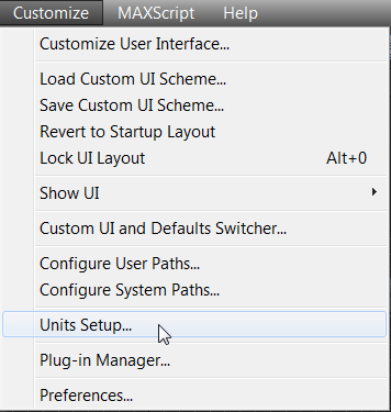
Figure 3-1: Accessing the Units Setup options

Figure 3-2: From the US Standard drop-down menu, choose Feet w/Decimal Inches.
Exercise 3.2: Importing a CAD Drawing
Using reference materials will help you efficiently create your 3D model and achieve a good likeness in your end result. The temptation to just wing it and start building the objects is strong, especially when time is short and you’re raring to go. You should always suppress this temptation in deference to a well-thought-out approach to the task. Sketches, photographs, and drawings can all be used as resources for the modeling process. Not only are references useful for giving you a clear direction in which to head, but you can also use them directly in the 3ds Max software to help you model. Photos, especially those taken from different sides of the intended model, can be added to a scene as background images to help you shape your model.
For this chapter, you will be using an AutoCAD drawing as the reference and as a template to build the walls, doors, and windows. You will be supplied with a CAD drawing that will make it much easier to follow the reference.
Figure 3-3 shows the room that you will create in this chapter. There are a few changes from the original room. The opening that leads to the hallway is going to become a door. We will add decorative elements, such as a fancy baseboard.
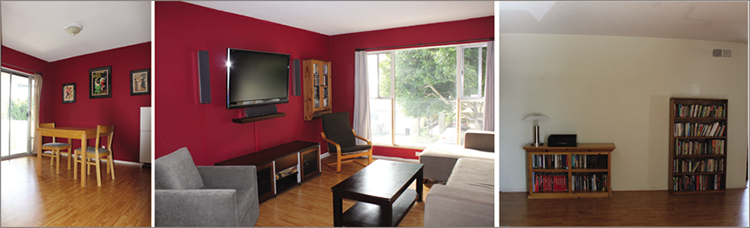
Figure 3-3: Images of the room to be created
- Select the Application button (
 ) ⇒ Manage ⇒ Set Project Folder and choose the
 c03_ArchModelproject folder, downloaded from the book’s web page at www.sybex.com/go/3dsmax2015essentials. For this procedure, either continue with file from previous exercise or use thec03_ex2_import_start.maxfile. - Again, select the Application button and choose Import ⇒ Import. Because you have already set your project to the ArchModel project, you will be taken straight to the
importfolder for that project. - Select the
Room.dwgfile. This is an AutoCAD drawing file that contains no 3D objects; it contains a drawing using 2D lines. Click OK. The AutoCAD DWG/DXF Import Options dialog box will open, as shown in Figure 3-4.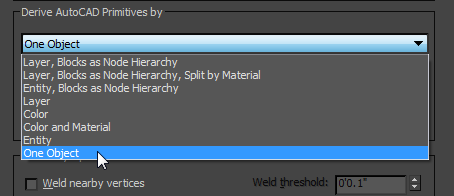
Figure 3-4: The AutoCAD DWG/DXF Import Options dialog box
- In the Derive AutoCAD Primitives By drop-down menu, choose One Object and then click OK. The AutoCAD drawing shown in Figure 3-5 will appear.
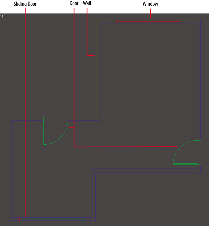
Figure 3-5: An AutoCAD drawing showing walls, doors, and window
- Select the imported AutoCAD drawing, and then choose the Move tool in the main toolbar. At the bottom of the interface are the Transform Type-Ins and three type-in boxes labeled X, Y, and Z.
- Change the X, Y, and Z values in the type-in boxes to X: 0′0.0″, Y: 0′0.0″, and Z: 0′0.0″. This will center the AutoCAD drawing of the floor plan to the center of the environment.
- In the command panel, go to the Create panel, and in the Name And Color rollout, rename the AutoCAD drawing Floorplan.
- Save the file, and to check your work open
c03_ex2_import_end.max.
Building the Room
The Wall objects you will create are a part of the AEC Extended objects and are designed for use in the architectural, engineering, and construction fields.
Exercise 3.3: Creating the Walls
To perform this exercise, you can use your completed file from Exercise 3.2,or you can load c03_ex3_walls_start.max from the Scenes folder of the c03_ArchModel project on the book’s companion web page at www.sybex.com/go/3dsmax2015essentials.
- Select and maximize the Top viewport (Alt+W).
- In the main toolbar, click and hold the Snaps Toggle button, and from the tool flyout, choose the 2D Snaps button (
 ).
). - Right-click the Snaps Toggle button to bring up the Grid And Snap Settings dialog box.
- Uncheck Grid Points and check Vertex, as shown in Figure 3-6.
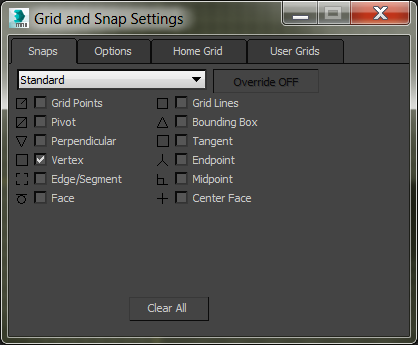
Figure 3-6: The Grid and Snap Settings dialog box
- Close the dialog box. This will make it possible to snap from the vertices in the AutoCAD drawing.
- Go to the Create panel, and from the Geometry drop-down menu choose AEC Extended and click the Wall button.
- You should see the wall parameters:
- Set Width to 0′5.0″ unless it is already set to this value. This will define the thickness of the wall.
- Set Height to 8′0.0″ unless it is already set to this value. This will define the height of the wall.
- Change Justification to Left, as shown in Figure 3-7.
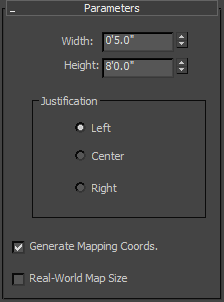
Figure 3-7: The Parameters rollout for the Wall object
- In the Top viewport, click and release an outside corner of the room in the AutoCAD drawing; then move in a clockwise direction to a connected corner, and click to set the position of that corner. This will create a wall 0′5.0″ thick and 8′0.0″ tall between the two corners you clicked.
- Continue around the room, clicking the outside wall corners, making sure you snap to the vertex of the lines at each corner. Disregard the doors and windows in the drawing and put your walls right over them.
- When you have made it all the way around the room, click the corner where you started.
- A Spline pop-up warning will ask, Weld Point? Click Yes and right-click to release the wall primitive.
- Press Alt+W to return to the four-viewport layout, and look at the walls in the Perspective viewport. The finished wall is shown in Figure 3-8.
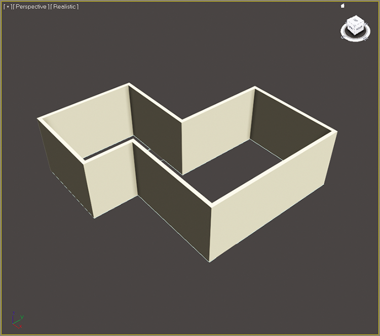
Figure 3-8: The finished wall shown in the Perspective viewport
- With the wall selected, go to the Modify panel and look at the parameters.
- In the modifier stack, click the black box with the plus sign.
- To edit the walls—say, to straighten out a wall or extend a wall to make a space bigger—select the Vertex component in the Modify panel.
- From the Top viewport, at the corners of the room, you should see small plus signs. The plus signs are the wall object vertices, allowing the walls to be edited. Select one of the vertices and move it to adjust the wall sections it is connected to.
- Click the Segment component, and then click a wall in your scene.
- You can use the Parameters section at the bottom of the rollout to change the settings for the wall, as shown in Figure 3-9.
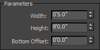
Figure 3-9: Wall parameters
- Save the scene file. To check your work, open
c03_ex3_walls_end.max. Now that the walls are laid out, we’ll move on to the doors.
Exercise 3.4: Creating the Doors
The 3ds Max Door objects that are available allow you to control the look of the door—not just the size but the frame and glass inserts as well. They also let you determine whether the door is open or closed. The types of door are Pivot (which is the most common), BiFold, and Sliding. To perform this exercise, you can use your previous file from the ArchModel project, or you can load c03_ex4_doors_start.max from the Scenes folder of the c03_ArchModel project on the book’s companion web page at www.sybex.com/go/3dsmax2015essentials.
- Select the Wall object if it isn’t already selected.
- Turn on See-Through mode using Alt+X. This will make the wall appear slightly transparent with a gray cast, but you will be able to see the AutoCAD drawing underneath.
- Go to the Create panel. From the drop-down menu, choose Doors. Choose Pivot under Object Type.
- Make sure the Top viewport is active, and zoom in on the door in the horizontal wall on the left in the AutoCAD drawing.
- The 2D Snaps Toggle button should still be active. If it’s not active, go to the main toolbar and click the 3D Snaps Toggle button, hold it down, and choose 2D Snap from the flyout.
- Starting at the left of the door opening on the outside of the wall, click and drag to the right side of the opening in the AutoCAD drawing underneath until it snaps; then release the mouse button. Then move the cursor and click the opposite side of the wall to set the door thickness.
- Now move the cursor toward the top of the viewport to adjust the door height.
- Click again to set any height. Don’t try to get the exact height; you will set the correct height in the next step.
- Go to the Modify panel and enter the correct value for the Height parameter for the door: 6′8.0″. Check Flip Hinge, as shown in Figure 3-10. Flip Hinge sets the edge on which the door swings.

Figure 3-10: The Door object parameters
- In the main toolbar, click the Select and Link tool (
 ), and click and drag from the door to the wall, as shown in Figure 3-11. This will make a doorway opening in the wall. The next type of door to be added is the sliding glass door, as shown previously in Figure 3-3 (left image).
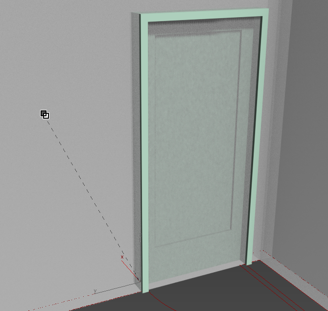
Figure 3-11: Use the Select And Link tool to create an opening in the wall for the door. This is necessary only if autolinking doesn’t work.
- In the Top viewport, zoom into the sliding door in the AutoCAD drawing.
- In the Create panel, choose Sliding under Object Type.
- Start by clicking and dragging from the right outside of the door to the left outside of the door, making sure to snap to the vertices where the door lines meet the wall lines. This will establish the width of the sliding door. Release the mouse button.
- Move your cursor to the inside of the door and click when your cursor snaps to the vertex.
- Click and drag the cursor to set any height, and click to finish.
- Don’t worry if you can’t get the height correct; just type 6′8.0″ in the Height Type-In field, as you did for the previous door.
- Switch to the Perspective viewport and check to see if the sliding door looks correct.
- Use the Select and Link tool and click and drag from the door to the wall to create the opening in the wall. The finished sliding door is shown in Figure 3-12.

Figure 3-12: The sliding door in the wall
- Add the remaining door by repeating steps 2–10.
- This is a good time to save your file. To check your work, open
c03_ex4_doors_end.max. You will create the window in the room in the next exercise.
Exercise 3.5: Creating the Window
AEC Window objects work in a way that is similar to the way the Wall and Door objects work. There are six window types: Awning, Fixed, Projected, Casement, Pivoted, and Sliding. You will be using the Fixed window for this section. You can continue with your file from the previous exercise, or you can load c03_ex5_windows_start.max from the Scenes folder of the ArchModel project on the companion web page to continue.
- Go to the Create panel, and from the drop-down menu, choose Windows. Choose Fixed under Object Type.
- In the main toolbar, click and hold the Snaps Toggle button. This will bring up the Snaps flyout. Choose the 2D Snaps button.
- Create the Window object as you did the Door objects: Use the snaps to click/drag from left to right, following the drawing; then drag to create the depth and then the height.
- In the Modify panel, go to the Fixed Window parameters and change Height to 6′0.0″. If the automatic linking failed to work, move on to the next step. If it does create the cutout, skip to step 6.
- Use the Select and Link tool and click from the window to the wall to create the opening in the wall, just as with the doors.
- Press S to turn off Snaps.
- Switch to a Perspective viewport so you can see the newly created window; then select and move the window up so it is centered on the wall, as shown in Figure 3-13.
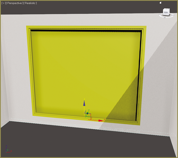
Figure 3-13: The window is centered on the wall.
- Save the file for use in the next section. To check the finished file, open
c03_ex5_window_end.max. The model to this point is shown in Figure 3-14.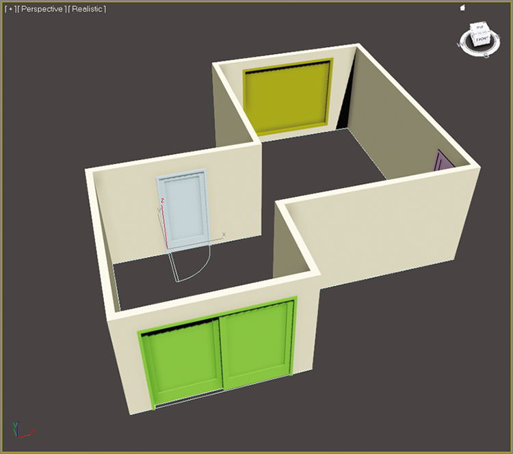
Figure 3-14: Walls with doors and a window
Exercise 3.6: Adding a Floor and a Ceiling
You can continue with your file from the previous exercise, or you can load c03_ex6_floor_start.max from the Scenes folder of the ArchModel project on the companion web page. What’s a room without a floor and ceiling? Not any room we want to walk into. To create the floor and ceiling for your room, you will use the Line tool to create a shape:
- Go to the Create panel and click the Shapes button (
 ); then click the Line tool, as shown in Figure 3-15.
 - Press S on your keyboard to turn on the Snaps Toggle tool.
- In the Top viewport, click the outside corner of the room, then click the other corners around the room in a clockwise direction, and then click again the corner where you started.
- The Spline dialog box will appear. Click Yes. This closes the line to form a closed shape.
- Choose the Select Object tool (Q), and select the line you just created, if it is not already selected.
- Go to the Modify panel (
 ), and from the Modifier List drop-down menu, choose Extrude, as shown in Figure 3-16.
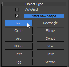
Figure 3-15: Select the Line tool.
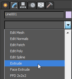
Figure 3-16: From the Modifier List drop-down menu, choose Extrude.
- Now look at the Extrude parameters, and change the Amount value to 0′0.1″. You need to give just a little thickness to the floor.
- Switch to the Front viewport, and move the new Floor object down so the top of the floor lines up with the bottom of the walls. Turn off the Snap tool (S).
- Rename the new object Floor. To create the ceiling, you are going to make a clone of the floor.
- Select the floor, and while holding the Shift key, move the Floor object up to the top of the Wall object.
- Let go of the mouse button; a Clone Options dialog box will appear, as shown in Figure 3-17.
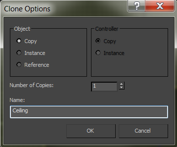
Figure 3-17: The Clone Options dialog box
- Choose Copy from the Object section, rename the object Ceiling, and click OK.
- Center your cursor over the Ceiling object and right-click.
- From the quad menu, choose Hide Selection.
- When you are ready to have the ceiling back in your scene, you can right-click anywhere in your scene and select Unhide All.
- Save the file, and to check your progress open
c03_ex6_floor_end.max.
Adding Special Details to the Room
In architectural terminology, a baseboard is a board covering the area where the wall meets the floor. Baseboards are used to cover the gap between the wall and the floor as well as add a sense of style to a room. An example of the baseboard we will be creating is shown in Figure 3-18.
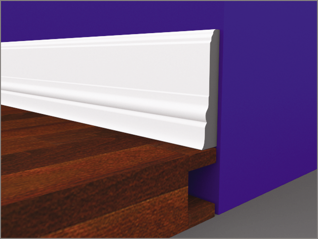
Figure 3-18: The baseboard molding
This room has a baseboard but not a very good one, so creating a more stylish one would be a great way to add some pizzazz to the room. Also, feel free to modify the baseboard to meet your skill level with the Line tool.
Exercise 3.7: Creating Baseboard Moldings
You can use your file from the previous exercise, or you can load c03_ex7_details_start.max from the Scenes folder of the ArchModel project on the book’s companion web page. To begin creating the baseboard, you will use a spline that has already been created: the floor:
- In the Perspective viewport, select the Floor object.
- Select and maximize the Top viewport (Alt+W), and in the Edit menu, choose Duplicate ⇒ Clone.
- In the Clone Options dialog box, choose Copy and change the name to Baseboard Path. Click OK
- In the Modify panel, remove the Extrude modifier by right-clicking the modifier in the modifier stack and choosing Delete when the context menu appears, as shown in Figure 3-19.
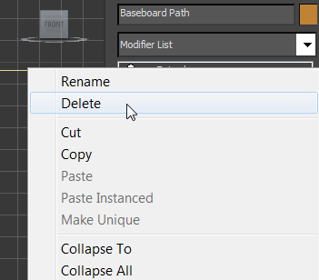
Figure 3-19: Deleting the Extrude modifier in the modifier stack
- In the modifier stack, click the plus sign in the black box to expand the Line entry to display the sub-objects of the line. Select Spline mode.
- Select the sub-object spline of the baseboard line. It will turn red when selected. You may not be able to see it because the walls are on top of the shape.
- In the Geometry rollout, scroll down to Outline.
- In the Outline Type-In, which is to the right of the Outline button, change the amount to –0′6.0″, as shown in Figure 3-20.
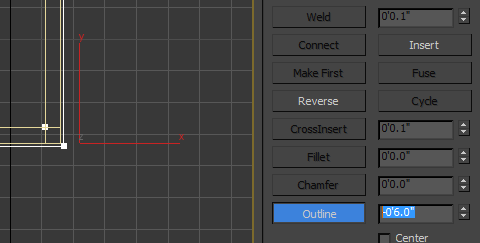
Figure 3-20: Change the Outline amount to –0′6.0″ to offset the spline.
- Select the original spline and delete it. Click Line to exit Spline mode. Because you are using the newly created spline for the baseboards, you don’t need the original line. Now you’ll create the shape of the molding, shown in Figure 3-21.
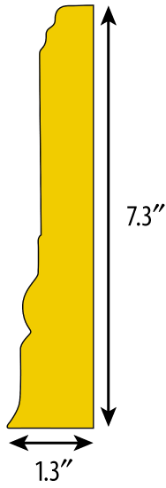
Figure 3-21: Profile of the baseboard molding
- Switch from the Top viewport to the Front viewport.
- Click the Application button, and choose Import ⇒ Merge. From the
Scenesfolder of the ArchModel project folder, choose theBaseboard Image Plane.maxfile. Click Open. - Select the Baseboard Image Plane object. Click OK in the Merge dialog box.
- Switch to the Front viewport and change the viewport shading to Realistic. Enter Isolate Selection mode (
 ) by selecting the icon at the bottom of the interface below the timeline (F3). This will hide everything in the scene except the image plane.
 - Choose Create ⇒ Shapes ⇒ Line, and at the top-right corner of the baseboard, click and release the left mouse button. This will create a corner point.
- Move the mouse to the left, where the baseboard begins to curve down, and click and drag to create a Bezier vertex. This is a vertex type that has handles, which allow for greater control over the curve in the line segments.
- Drag until the curve is following the curve of the baseboard.
- Now continue around the baseboard cross section until you are back at the first vertex that you created. Click the first vertex and select Yes from the dialog box to close the spline.
- Right-click to release the Line tool.
- Rename the shape Baseboard Shape. If the line needs to be edited, go to the Modify panel and select Vertex mode. In Vertex mode, you can edit the path to match the image on the image plane.
- Exit Isolate Selection mode and then select the baseboard path. Go to the Modify panel, and from the Modifier List, choose Sweep.
- In the Section Type rollout, choose Use Custom Section, and in the Custom Section Types area, select Pick.
- Pick the baseboard shape to create the baseboard, as shown in Figure 3-22. Some parameters need to be adjusted.
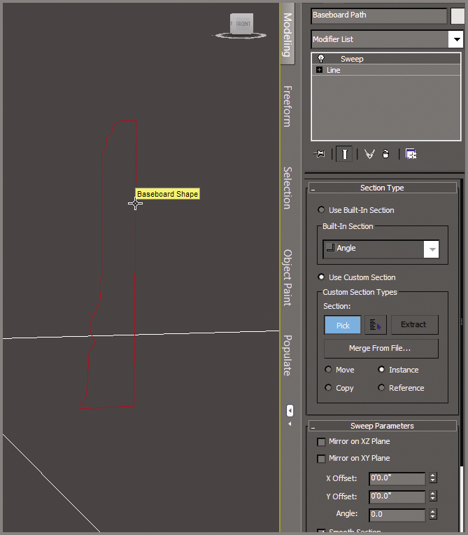
Figure 3-22: Picking the baseboard shape in the Sweep modifier
- In the Sweep Parameters rollout, check the box next to Mirror On XZ Plane. This will flip the baseboard shape so it is facing in toward the room. The baseboard molding should run along the floor except at the door openings. Right now, the molding is going straight through the door opening, as shown in Figure 3-23. It isn’t difficult to fix; just edit the path.
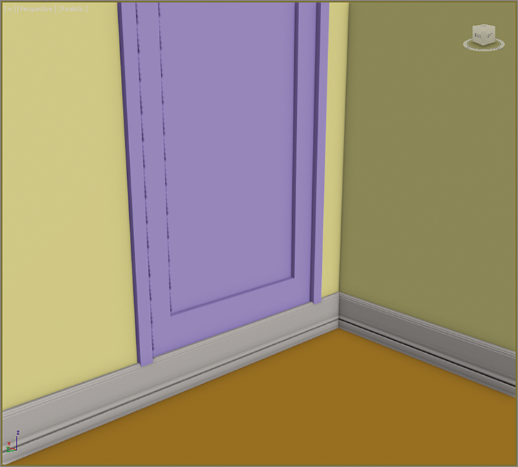
Figure 3-23: The baseboard molding is going through the door opening.
- Switch to a Perspective viewport (Alt+W) to exit Maximize Viewport and then Ctrl+click the floor plan and the baseboard to select them both.
- Enter Isolate Selection mode (Alt+Q), and then select just the baseboard.
- Zoom in on the door on the right of the Top viewport.
- Go to the Modify panel, and in the modifier stack, choose Vertex mode.
- Go to the Geometry rollout and click the Refine button.
- Move to the baseboard spline and click directly on the spline on both sides of the door to add new vertices. Right-click to exit Refine.
- Switch to Segment mode; select the segment in between the two new vertices and delete it, as shown in Figure 3-24.
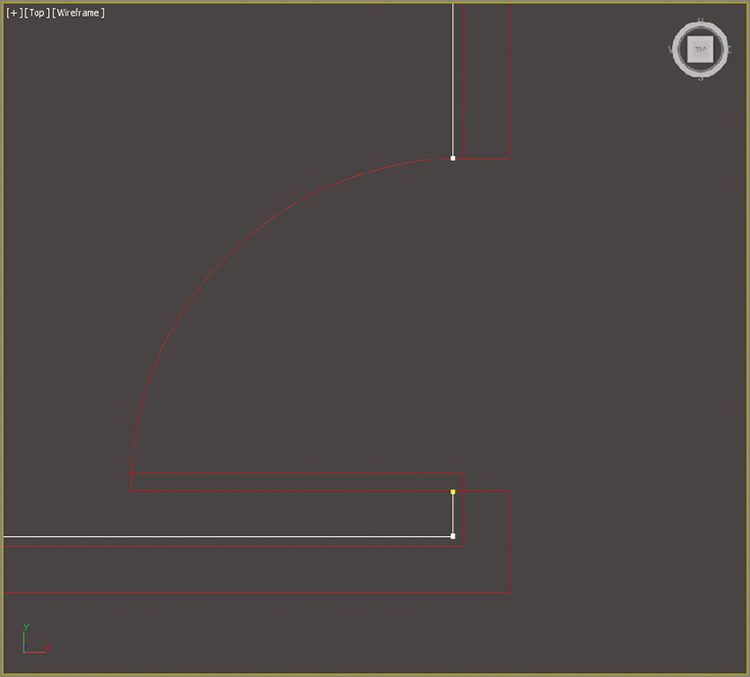
Figure 3-24: Use Refine to add two new vertices on either side of the door; then delete the segment.
- Repeat the same process for the remaining pivot door and sliding door.
- When you finish, select the Sweep modifier in the Modify Stack to exit Edit mode in the Sweep modifier. Exit Isolate Selection mode. The finished results of the Sweep modifier are shown in Figure 3-25.
- Save the file. You can check your work by opening
c03_ex7_detail_end.max.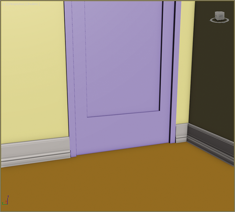
Figure 3-25: The baseboard with proper gaps at the doors