
Chapter 8
Character Modeling Part II
Realistic computer-generated (CG) characters are common in television and films; they appear as stunt doubles, as members of vast crowds, and as primary characters. Sometimes using a CG character works better than using a real person. Using a CG stunt double is safer and sometimes cheaper than using a live stunt person, and weird creatures can be created with better clarity by using CG rather than puppetry or special makeup effects.
In this chapter, you will continue with the model of the alien, focusing on using the Editable Poly toolset to create an alien model suitable for character animation and for use in a game engine.
This chapter includes the following topics:
- Creating the alien head
- Creating the alien hands
- Creating the alien feet
- Completing the alien
Creating the Alien Head
The alien’s head will consist of three parts: the neck, the head shape, and the eye and mouth. The easiest way to create these is to start with the head shape.
Exercise 8.1: Blocking Out the Head
The head is the most important part of the alien, or any humanoid/anthropomorphic (human characteristics) character. Its most important feature is the face, which communicates expressions and moods and allows people to relate to this character. The head itself is easy, but the face is another story. The face is more complex and needs more detail than any other part of the alien. Either continue with the previous file from Chapter 7 or open the c08_ex1_head_start.max scene file in the Scenes folder of the c08_CharacterModel project. This process starts with a simple primitive box.
- In the Create panel ⇒ Geometry ⇒ Standard Primitives, select Box. In the Perspective viewport, create a box with Length = 9.0, Width = 9.0, Height = 13.5, Length Segs = 3, Width Segs = 3, and Height = 3. Enter See-Through mode (Alt+X), and then move the box so it is aligned with the alien head in the Left and Front viewports, as shown in Figure 8-1.
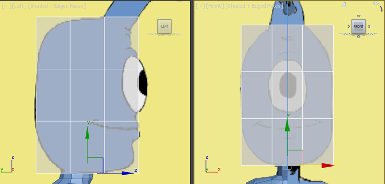
Figure 8-1: Align the box with the alien head.
- In the Ribbon ⇒ Modeling tab ⇒ Polygon Modeling choose Convert To Poly.
- The edges that are running around the eyes need to be moved so that they surround the eyes. Enter Edge mode, and from the Front viewport select the top horizontal edge (make sure the entire edge loop is selected by double-clicking) and move it above the eye. Repeat for all the edges around the eye so it looks like Figure 8-2.
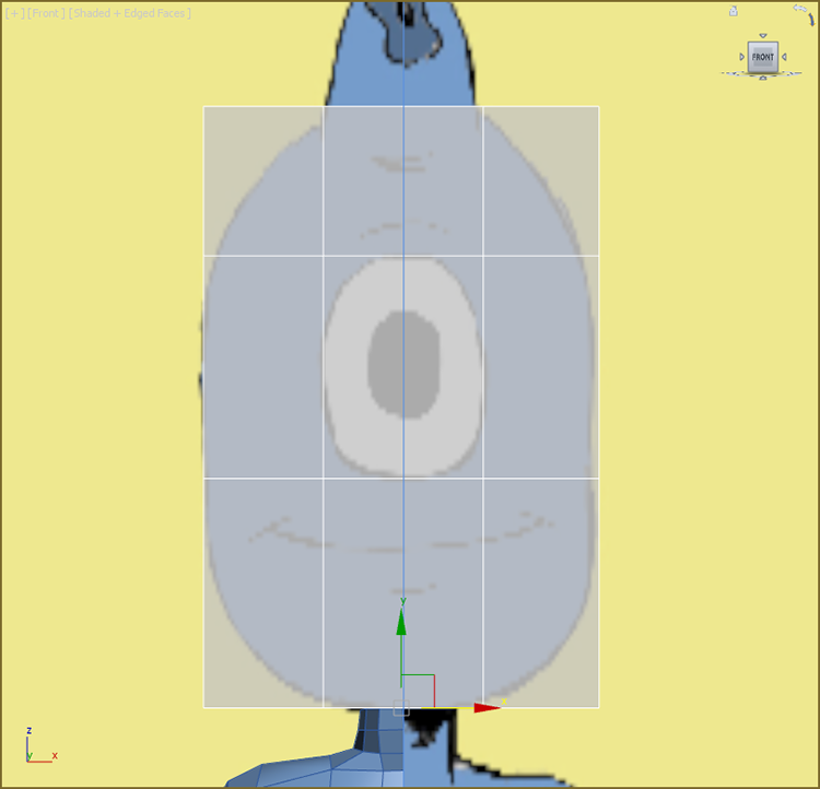
Figure 8-2: Move the edges so they surround the eye.
- Now it’s time to make this box more spherical. Enter Vertex mode and from the Front viewport select the four vertices at the corners.
- Switch to the Scale tool (R), make sure the Transform gizmo is in the center of the box, and scale by centering the cursor inside the scale transform triangle and dragging until the corners are aligned with the image plane.
- Change to the Left viewport and repeat the process. Then repeat the process from the Top viewport. When finished, the box will look like Figure 8-3. Exit Vertex mode.
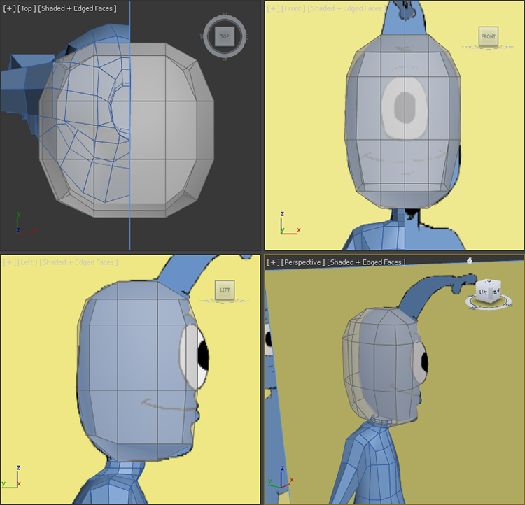
Figure 8-3: By selecting the corners and scaling them inward, you make the head more spherical.
Save the file you are working with. To check your work open the c08_ex1_head_end.max scene file in the scenes folder of the c08_CharacterModel project folder.
Exercise 8.2: Building the Nose
It’s time to build the alien’s “nose,” which is coming out of his forehead. Either continue with the previous file or open the c08_ex2_nose_start.max scene file in the scenes folder of the c08_CharacterModel project folder.
- Enter Polygon mode, and select the polygon at the top of the head where the forehead is.
- In the Ribbon ⇒ Modeling tab ⇒ Polygons ⇒ Bevel ⇒ Bevel Settings, set the Bevel Height to 2.5 and the Bevel Outline to -0.15, and then click OK.
- Repeat the process from step 2 by selecting the Bevel Setting, set the Bevel Height to 2.5 and the Bevel Outline to -0.5, and click OK.
- Repeat the bevel again on the nose using the settings from the previous step.
- Switch to Vertex mode and adjust the vertices to follow the alien’s nose in the image plane, as shown in Figure 8-4. Exit Vertex mode when finished.
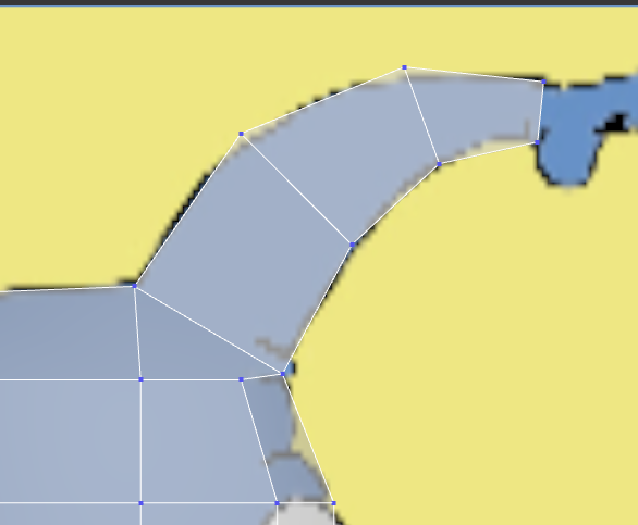
Figure 8-4: In Vertex mode edit the alien’s nose to match the image plane.
- Enter Polygon mode and select the polygon at the eye.
- To create the eye socket go to the Ribbon ⇒ Modeling tab ⇒ Polygons ⇒ Bevel ⇒ Bevel Settings. You will be creating three bevels:
- Bevel 1:
- Bevel Height: 0.0
- Bevel Outline: -0.1
- Click the Apply And Continue button (
 ).
).
- Bevel 2:
- Bevel Height: -0.1
- Bevel Outline: 0.0
- Click Apply And Continue.
- Bevel 3:
- Bevel Height: -1.5
- Bevel Outline: 0.0
- Click OK.
- To add a bit of a ridge around the eye you will move around some of the edges that you created in the previous step. Enter Edge mode and double-click the edge on the inside of the eye socket.
- Select the Move tool and move the edge about halfway to the inside of the eye socket.
- Select the edge on the top inside of the eye socket, and move this edge toward the outside of the eye socket. The eye socket will now resemble Figure 8-5.
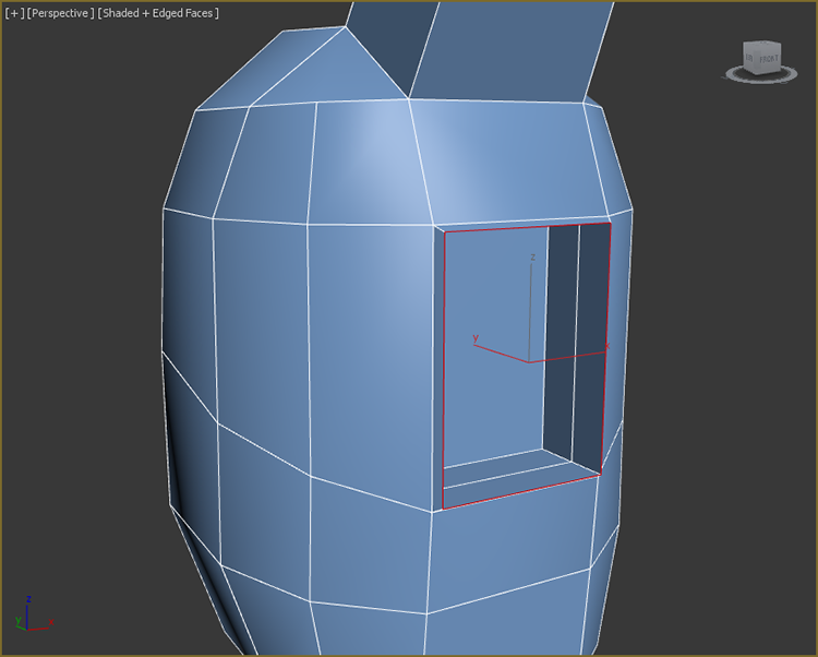
Figure 8-5: Move the new edges to create a small ridge around the eye socket.
- The nose needs more definition, so at the base add another edge loop using SwiftLoop (select the Ribbon ⇒ Modeling tab ⇒ Edit ⇒ SwiftLoop).
- To finish the alien’s nose enter Edge mode on the Ribbon ⇒ Modeling tab ⇒ Polygon Modeling tab, and at the end of the nose select the top and bottom edges. Make sure the Scale gizmo is in the center of the selected edges. If it isn’t in the center, change the Use Center flyout to Use Selection Center, as shown in Figure 8-6.
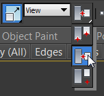
Figure 8-6: To make sure the Scale gizmo is at the center of the selected edges, select Use Selection Center from the Use Center flyout on the main toolbar.
- Switch to Polygon mode and from the Modeling tab ⇒ Polygons ⇒ Bevel ⇒ Bevel Settings, you will be creating four bevels for the nose:
- Bevel 1:
- Bevel Height: 0.0
- Bevel Outline: 0.2
- Click Apply And Continue.
- Bevel 2:
- Bevel Height: 0.3
- Bevel Outline: 0.0
- Click Apply And Continue.
- Bevel 3:
- Bevel Height: 0.0
- Bevel Outline: -0.2
- Click Apply And Continue.
- Bevel 4:
- Bevel Height: -0.2
- Bevel Outline: -0.15
- Click OK.
- The head started out as a box, and even with all the changes it still has a hint of the box about it. Deleting a few edges will give the head a more rounded look. Select the edges where the corners of the box were, as shown in Figure 8-7.
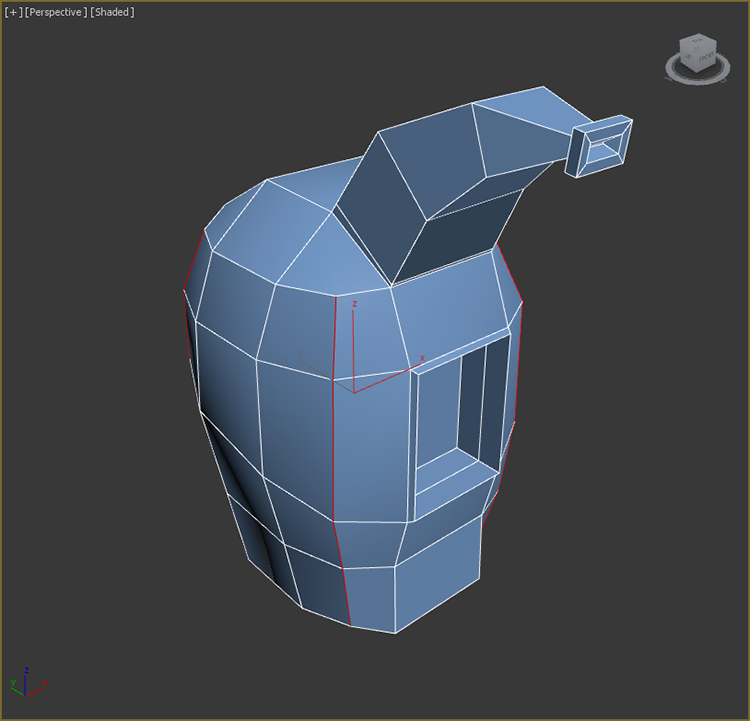
Figure 8-7: Select the edges on the head that were once the corners of the original box.
- To delete the edges hold down the Ctrl key and press the Backspace key on your keyboard. This is a shortcut for choosing the Ribbon ⇒ Modeling tab ⇒ Edges ⇒ Remove. It is very important to hold down Ctrl while using this tool so that it will remove the associated vertices where edges cross the remaining edges.
- This makes the head thinner than before, so switch to Vertex mode, change to the Front viewport, and turn on See-Through mode (Alt+X). Move vertices out to match Figure 8-8. Repeat the process for the Left viewport. Exit See-Through mode.
Figure 8-8: From the Front viewport, in Vertex mode, move the vertices so they match the alien’s jaw line in the image plane (right). Repeat from the Left viewport (left).
- To test the head so far, turn on Use NURMS; in the Use NURMS tab set the iterations to 2. This will show the head smoothed out so you will be able to see any flaws so far. At this point, you can edit the head to refine and more closely match the image plane, as shown in Figure 8-9.
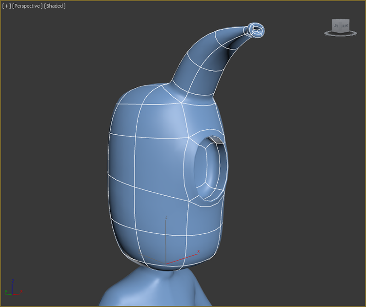
Figure 8-9: The refined head
The head is not complete; the nose tip needs to be refined and the alien’s mouth has not been started. These parts will be addressed later in the chapter. Save the file you are working with. To check your work open the c08_ex2_nose_end.max scene file in the scenes folder of the c08_CharacterModel project.
Building the Alien Hand
The alien hand is simple and cartoonish, with just three fingers and a thumb. You won’t be adding details such as lines on the palm or nails. In this section, you will create three simple fingers for the alien.
Exercise 8.3: Building the Palm of the Hand
Continue with the previous exercise’s scene file, or open the c08_ex3_palm_start.max scene file in the scenes folder of the c08_CharacterModel project folder. The first thing to do is to merge in the image plane containing the hand.
- In the Applications menu choose Import ⇒ Merge.
- Navigate to the
scenesfolder of thec08_CharacterModelproject folder. Openc08_ex3_hand_image plane.max. - In the Merge dialog box, select Hand Image Plane and click OK. The image plane will land in the correct spot, below the arm. If it is not in the correct position, move the image plane so it is beneath the end of the arm, as shown in Figure 8-10.
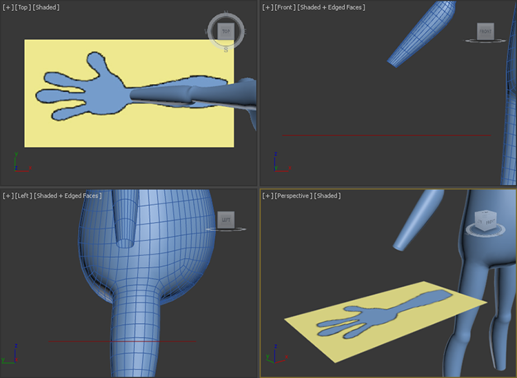
Figure 8-10: The hand image plane positioned at the end of the wrist
- In the Create panel ⇒ Geometry ⇒ Standard Primitives, in the Top viewport, create a box with the parameters shown in Figure 8-11. Name the box Alien Hand.
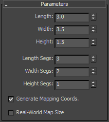
Figure 8-11: The parameters for the box that will create the hand
- In the Ribbon ⇒ Modeling tab choose Polygon Modeling ⇒ Convert to Poly.
- Turn on See-Through mode (Alt+X).
Save the file you are working with. To check your work you can open the c08_ex3_palm_end.max scene file in the scenes folder of the c08_CharacterModel project folder.
Exercise 8.4: Beveling the Fingers
Using Bevel to create the fingers allows you to extrude and scale the shape of the fingers with a single tool. Continue with the previous exercise’s scene file, or open the c08_ex4_fingers_start.max scene file in the scenes folder of the c08_CharacterModel project folder.
- Select the Alien Hand object. Enter Vertex mode if you are not already in it. Use the Move tool to rearrange the vertices to match what is shown in Figure 8-12.
- In Polygon mode, select the three polygons on the front of the hand, where the fingers will be, as shown in Figure 8-13.
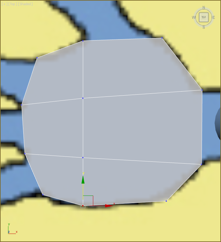
Figure 8-12: Rearrange the vertices to match the palm in the image plane.
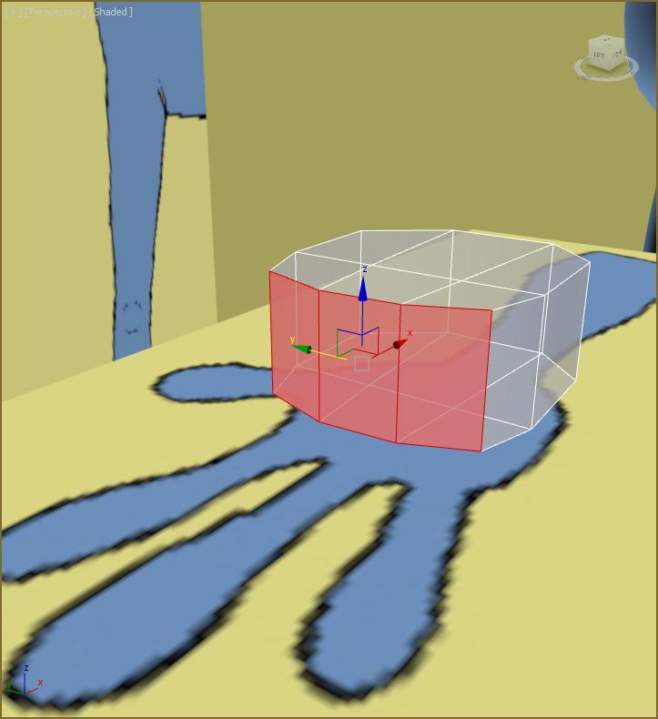
Figure 8-13: Select the three polygons to prepare for beveling the fingers.
- From the Ribbon choose the Modeling tab ⇒ Polygons ⇒ Bevel ⇒ Bevel Settings, set Extrusion Type to By Polygon, enter a Height value of 1.2, and press Enter. Set the Outline amount to -0.2 and press Enter. Click the Apply And Continue button. Now enter a Height value of 1.2 and press Enter. Set Outline to 0.3, press Enter, and click Apply And Continue. Now enter a Height value of 1.2 and press Enter. Set Outline to -0.3, press Enter, and click OK.
- Select the polygon on the side of the palm close to the wrist where the thumb will be. In the Modeling tab of the Ribbon choose Polygons ⇒ Bevel ⇒ Bevel Settings, set Extrusion Type to By Polygon, enter a Height value of 0.6, and press Enter. Set Outline to -0.3, press Enter, and click OK.
- Switch to Vertex mode; arrange the vertices of the new thumb extrude to follow the image plane, as shown in Figure 8-14.
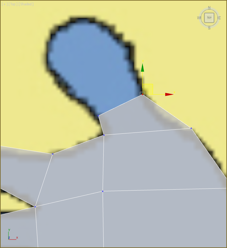
Figure 8-14: Rearrange the thumb vertices to follow the thumb in the image plane.
- Create a new bevel, set Height to 0.9 and Outline to 0.25, and press Enter. Then click Apply And Continue. Set Height to 0.9 and Outline to 0.25, press Enter, and click OK.
- In the Ribbon select the Modeling tab ⇒ Edit ⇒ Use NURMS. In the Use NURMS tab, set Iterations to 2.
- Enter Vertex mode, and select and move the vertices to better fit the hand in the image plane shown in the Top viewport, as shown in Figure 8-15. Then switch to the Front viewport (F).
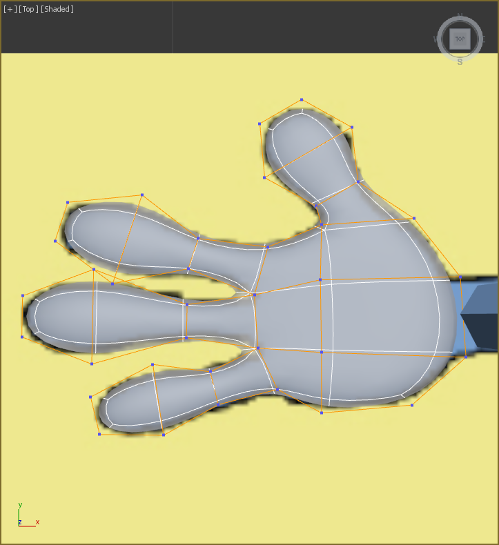
Figure 8-15: The hand from the Top viewport
If you continued with the file from the previous exercise, continue with steps 9–11. If you started with the
c08_ex4_fingers_start.maxscene file, skip to step 12. - In the Application menu choose Import ⇒ Merge.
- Navigate to the
scenesfolder of thec08_CharacterModelproject. Openc08_ex4_hand_image plane side.max. - In the Merge dialog box, select Hand Image Plane Side and click OK. The image plane will land in the correct spot, under the arm. If it is not in the correct position, move the image plane so it is under the end of the arm and lines up with the hand.
- Enter Vertex mode and continue to edit the hand to match the hand image plane side. The tops of the fingers need to be flattened out. You can also make whatever other changes you think appropriate.
- The thumb needs to be angled down. Enter Polygon mode, and select the polygon at the end of the thumb.
- In the Modeling tab of the Ribbon, choose Modify Selection ⇒ Grow, and click Grow twice to select the remaining thumb polygons.
- Switch to the Rotate tool, and in the main toolbar select Local from the Reference Coordinate System drop-down menu, as shown in Figure 8-16.
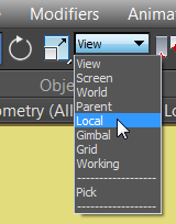
Figure 8-16: Select Local from the Reference Coordinate System drop-down menu.
- Rotate the polygons 60 degrees along the Y axis (use the green control handle on the gizmo).
- Switch to the Move tool and move the thumb polygons down into a more realistic position. Don’t worry if they don’t line up perfectly with the thumb in the image plane.
- Select the polygon at the wrist and delete it. Exit Polygon mode by clicking the Polygon icon button.
- From the Top viewport and in the main toolbar, select the Mirror tool (
 ). In the dialog box change Mirror Axis to Y and click OK. The completed hand is shown in Figure 8-17. Exit See-Through mode (Alt+X).
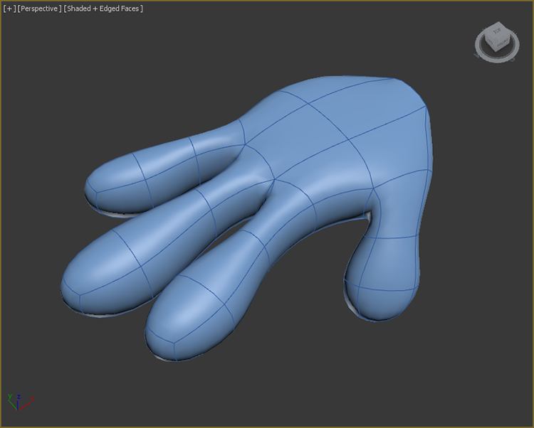
Figure 8-17: The final alien hand shown and isolated
Our alien has very simple hands: no nails, hair, wrinkles, or creases. It is not within the scope of this book to cover the tools to create these details. Use the tools you have been learning, and experiment with adding various details to the hands. Perhaps you can start by adding fingernails; you can do this by beveling polygons at the tip of the fingers. Save the file you are working with; to check your work open the c08_ex4_fingers_end.max scene file in the scenes folder of the c08_CharacterModel project.
Building the Foot
In this section, you will create a simple three-toed foot for the alien. The techniques are very similar to modeling the hand. You’ll start with a box to block out the foot, and then use Bevel to extrude the toes. Then you’ll refine the shape and add NURMS to smooth out the foot.
Exercise 8.5: Blocking Out the Foot
Continue with the previous exercise’s scene file, or open the c08_ex5_foot_start.max scene file in the scenes folder of the c08_CharacterModel project.
In the Application menu choose Import ⇒ Merge, and then navigate to the scenes folder of the c08_CharacterModel project. Open the file c08_ex5_foot_image plane.max. In the Merge dialog box, select Foot Image Plane and click OK. The image plane will land in the correct spot, under the leg. If it is not in the correct position, move the image plane so it is under the end of the leg.
- Select the alien body, head, hand, and the Hand Image Plane object, right-click to access the quad menu, and choose Hide Selected.
- From the Top viewport, go to the Create Panel ⇒ Geometry ⇒ Standard Primitives, and create a box with parameters of Length = 8.0, Width = 5.0, Height =3.0, Length Segs = 3, Width Segs = 3, and Height = 2.
- Turn on See-Through mode. From the Left viewport, switch to the Move tool, and move the box so it is aligned with the foot in the image plane. Line up the back of the box with the heel in the image plane.
- Convert the box to an editable polygon (from the Modeling tab of the Ribbon choose Polygon Modeling ⇒ Convert to Poly). Enter Vertex mode; from the Top viewport select the top two rows of vertices, change to the Scale tool, and scale the vertices together until they sit on the sides of the heel, as shown in Figure 8-18 (left images).
- Now select the second row of vertices from the top and move it down below the heel, as also shown in Figure 8-18 (right images).
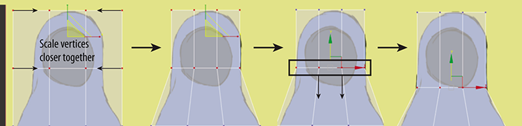
Figure 8-18: Select and scale the vertices together to form the heel; then select the second row from the top and move it down below the heel.
- Switch to the Left viewport. Select and rearrange the middle and top rows of vertices to match the image in Figure 8-19.
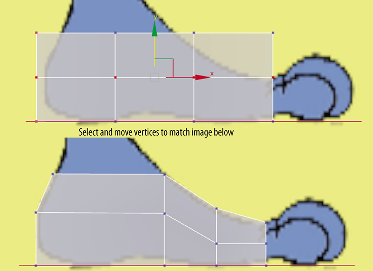
Figure 8-19: Edit the middle and top rows of vertices to further refine the foot.
- Switch back to the Top viewport, and arrange the line of vertices at the base of the toes to match the image in Figure 8-20. This will help correctly align the toes for the bevel.
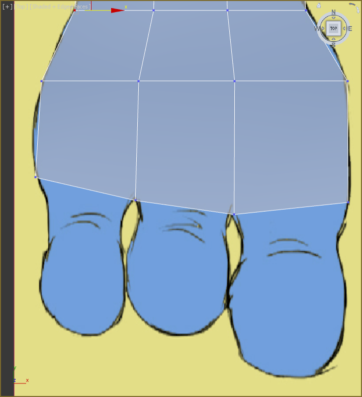
Figure 8-20: Edit the line of vertices at the base of the toes.
Save the file you are working with. To check your work open the c08_ex5_foot_end.max scene file in the scenes folder of the c08_CharacterModel project.
Exercise 8.6: Beveling the Toes
Like modeling the fingers, you’ll use Bevel, but instead of beveling all the toes at the same time, you will do one at a time, using different settings for each toe. Continue with the previous exercise’s scene file, or open the c08_ex6_toes_start.max scene file in the scenes folder of the c08_CharacterModel project.
- Switch to Polygon mode, and select the polygons at the front of the foot where the smallest toe is.
- From the Modeling tab of the ribbon choose Polygons ⇒ Bevel ⇒ Bevel Settings. In the Bevel caddy apply these settings:
Setting Bevel Type Height Outline Bevel 1 Local Normal 0.5 -0.3 Bevel 2 Local Normal 0.9 0.3 Bevel 3 Local Normal 0.9 -0.3 This will build the first toe; use the same technique to build the remaining toes. Don’t worry if the geometry overlaps; the geometry smoothing that the NURMS creates will fix it. The finalized toes are shown in Figure 8-21.
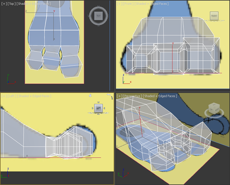
Figure 8-21: Toes extruded using Bevel
- Now select the three polygons on the top back of the foot and delete them.
- Enter Border mode (
 ). Border mode allows you to select a hole in a mesh so you can modify it with various tools. Select the border of the hole you made when you deleted the polygons in the previous step. This technique allows you to create the ankle.
 - Use the Shift+Move method you used on edges in the previous chapter. From the Left viewport, hold down Shift and move the border up along the Y axis.
- Switch to Vertex mode. Select and move the vertices at the top of the ankle in toward the ankle in the image plane.
- Switch to the Front viewport and repeat the process. When you have finished, exit Vertex mode. Exit See-Through mode and select Use NURMS; the results are shown in Figure 8-22.
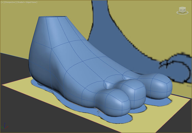
Figure 8-22: The finished foot with the ankle
Save the file. To check your work open the c08_ex6_toes_end.max scene file in the scenes folder of the c08_CharacterModel project.
Completing the Alien
Now that all the parts to the alien are complete, you need to bring them all together. Once the alien is whole you can further refine the model if desired. To begin this process, you need to attach the head, hand, and foot to the main alien body.
Exercise 8.7: Attaching to the Body
Attaching in itself is easy, just a button click, but there are some issues that need to be addressed first. To attach objects correctly you need the objects to have holes or borders where the objects attach to each other. It is recommended to have an equal number of edges on both objects going into the border, as shown in Figure 8-23.
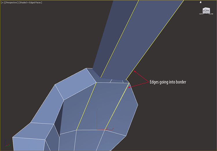
Figure 8-23: Hand and lower arm showing the borders meeting and the edges
Figure 8-23 shows the underside of the palm of the hand and the wrist of the alien body. It shows that an equal number of edges are present. Figure 8-24 shows the top side of the same palm and wrist. Notice how the wrist has an extra edge but the palm has two edges, the same as the underside.
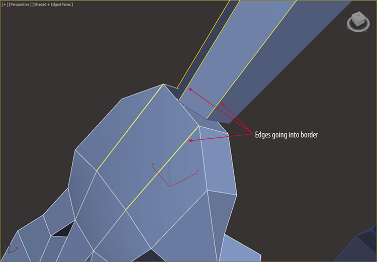
Figure 8-24: The top of the wrist has an extra edge.
In order to properly attach they have to have an equal number of edges, so you need to add one edge on the top side of the palm. You could use the SwiftLoop tool, but that would add a loop from the top side of the palm to the bottom side. That won’t do, so you’ll use the Cut tool. Continue with the previous exercise’s scene file, or open the c08_ex7_attach_start.max scene file in the scenes folder of the c08_CharacterModel project. If you continue with the file from the previous exercise, you will need to unhide the alien’s body, head, and hand. You can either delete the image planes or just keep them hidden. Turn off Use NURMS for the hand and foot.
- In the Modeling tab of the Ribbon choose Edit ⇒ Cut. Cut by clicking from the base of the finger to the border opening, as shown in Figure 8-25. Right-click in the viewport to exit the Cut tool.
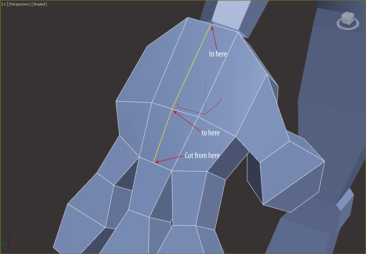
Figure 8-25: Use Cut to create new edges on the top of the hand.
- Select the Alien Body object, and in the Modeling tab choose ⇒ Geometry (All), click the Attach button, and then click on the hand. Now both the hand and body can be controlled with the same editable polygon parameters.
- Enter Border mode, and select the border of the wrist and palm (Ctrl+click to add both borders).
- In the Modeling tab choose Borders ⇒ Bridge. There’s no need to use the Bridge settings or caddy. Just click the Bridge button. You will see the new polygon bridge appear.
- Enter Edge mode, and double-click on the edge at the wrist.
- Select the Move tool and move the edge higher on the arm. In the main toolbar change the reference coordinate system to Local, and select Constrain To Edge in the ribbon Edit tab. When you have finished, select Constrain To None (
 ). Exit Edge mode by selecting the Edge mode icon.
- Time for the foot—it requires a different strategy. Select the foot, enter Vertex mode, and select the vertices shown in Figure 8-26 (left).
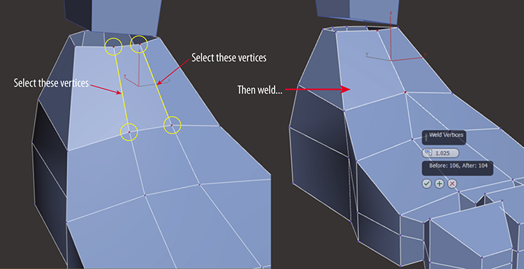
Figure 8-26: Select the four vertices on the top front of the foot (left). Use Weld to combine the edges (right).
- In the ribbon ⇒ Modeling tab ⇒ Vertices ⇒ Weld ⇒ Weld Setting caddy, set the Weld threshold to 1.025 (or use whatever value welds the vertices to match the right image in Figure 8-26). This will combine the horizontal vertices, as shown in Figure 8-26 (right). Repeat the process on the back of the foot. Exit Vertex mode.
- Using the Cut tool, cut an edge on the front of the lower leg to the bottom of the knee, as shown in Figure 8-27. Repeat for the back of the leg.
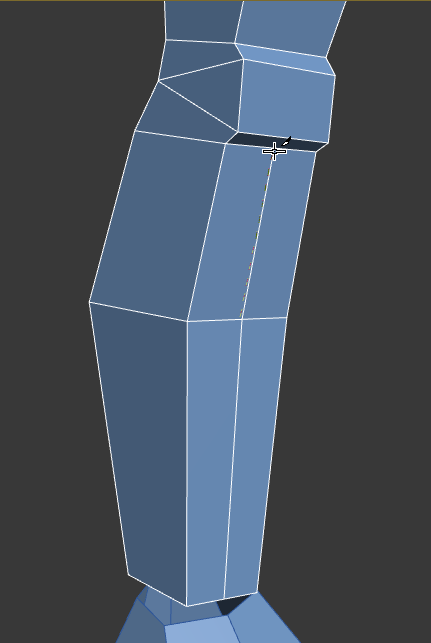
Figure 8-27: Use Cut to create an edge from the bottom of the lower leg to the bottom of the knee.
- Adding the edges to the leg will make the leg less square. Round out the leg by selecting and moving the vertices on the outer edge of the leg, as shown in Figure 8-28.
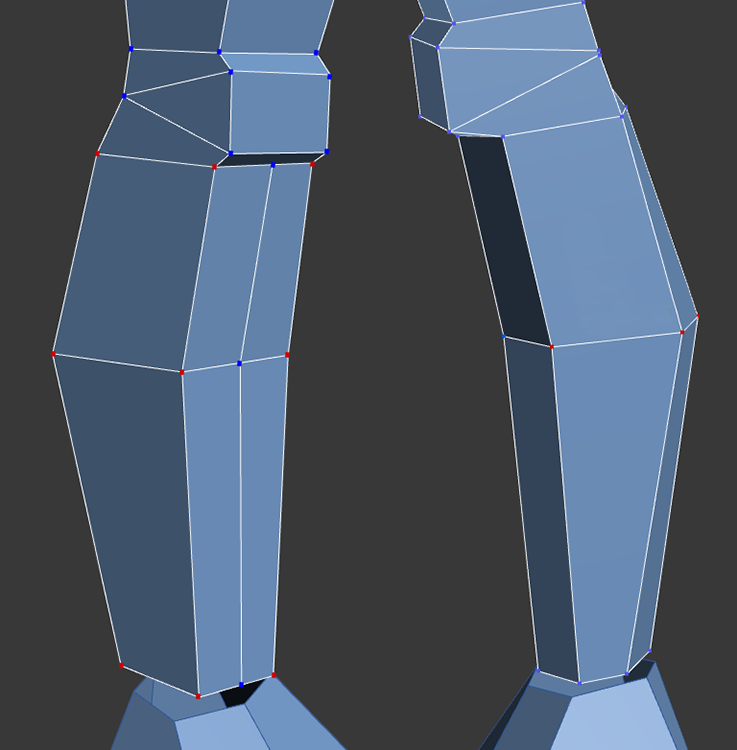
Figure 8-28: Select vertices on the outer edge of the leg and move them so the leg is more rounded.
- Now the foot is ready to be attached to the leg. In the Modeling tab choose Geometry (All) ⇒ Attach, and then click on the foot.
- Now you need to bring the two elements together. For the hand you used Bridge; this time you’ll use something different. In the Modeling tab choose Vertices ⇒ Target Weld (
 ). This tool allows you to select a vertex and weld it to a neighboring target vertex. Click on a vertex on the end of the leg and then on the neighboring vertex on the foot border, as shown in Figure 8-29.
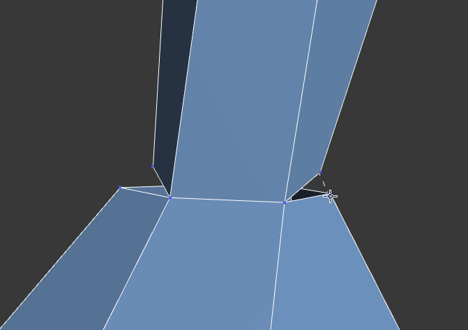
Figure 8-29: Attach the foot to the leg using Target Weld.
Save the file. To check your work open the c08_ex7_attach_end.max scene file in the scenes folder of the c08_CharacterModel project.
Exercise 8.8: Using Symmetry
This part is easy because you have done it before. Continue with the previous exercise’s scene file, or open the c08_ex8_symmetry_start.max scene file in the scenes folder of the c08_CharacterModel project.
- Select the Alien Body model.
- Choose the Modify panel ⇒ Modifier List ⇒ Symmetry.
- In the Symmetry modifier, Mirror Axis group, check the Flip box.
- You need to combine the two sides of the model, so from the ribbon choose the Modeling tab ⇒ Polygon Modeling ⇒ Collapse Stack.
Save the file you are working with. To check your work open the c08_ex8_symmetry_end.max scene file in the scenes folder of the c08_CharacterModel project.
Exercise 8.9: Finishing the Head
The head will require some of the same steps as the hand and foot. First, the edges at the base of the head have to be rearranged, and then some of the edges coming up to the neck need to be merged so that you have an equal number of edges on both objects. You need to do this before the attach can occur. Continue with the previous exercise’s scene file, or open the c08_ex9_head_start.max scene file in the scenes folder of the c08_CharacterModel project.
- In the Perspective viewport, zoom close into the underside of the head at the hole in the neck. Make sure you are looking at the front of the face.
- In the Modeling tab choose Edit ⇒ Cut. Then use the Cut tool to cut from the corner at the chin of the model down to the neck opening. It is important to start the cut from the vertex at the corner but finish in the middle of the edge at the neck, as shown in Figure 8-30.
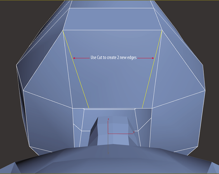
Figure 8-30: Use the Cut tool to add new edges.
- Enter Edge mode, and select the edges on either side of the new edges created in the previous step. Ctrl+click on the edges to select both.
- You cannot just delete the edges; you must remove them. In the Modeling tab choose Edges ⇒ Remove (the Backspace key is the keyboard shortcut), as shown in Figure 8-31. This is a simple way to rearrange edges. Repeat the process on the back of the head.
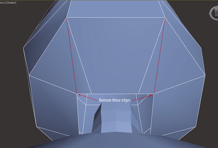
Figure 8-31: Select the old edges and use the Remove tool to properly delete them.
The opening for the neck is square, so you can switch to Vertex mode and just move them around until the opening is round, or…
- Switch to Border mode, select the neck border, and in the Modeling tab choose Geometry (All) ⇒ Cap Poly. This adds a polygon in the hole.
- Switch to Polygon mode and select the new cap polygon.
- In the Modeling tab choose Polygons ⇒ GeoPoly. This will rearrange the poly into a more rounded shape, as shown in Figure 8-32.
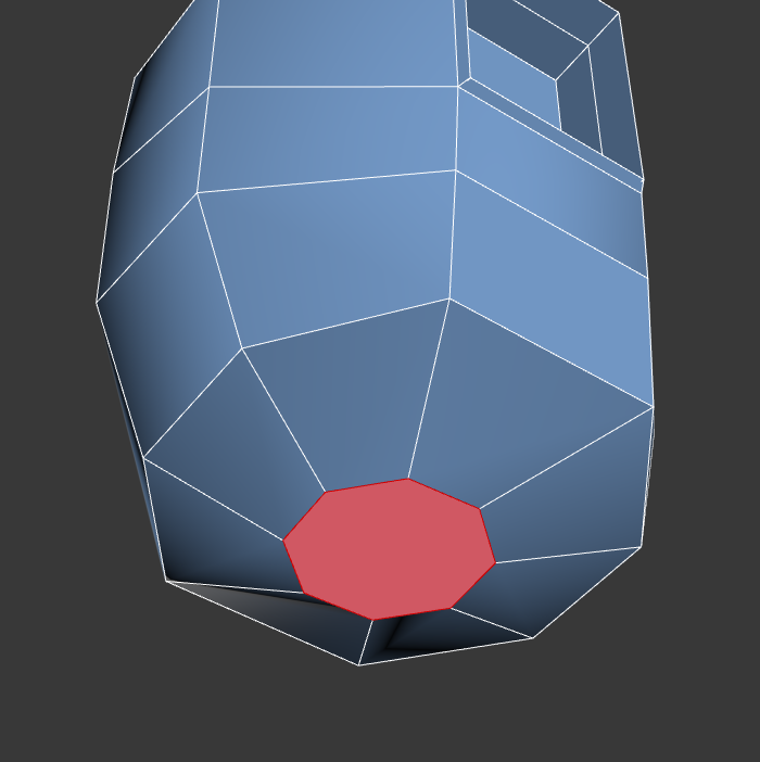
Figure 8-32: Use GeoPoly to rearrange the polygon into a circular shape.
- Now delete the selected polygon. Exit Polygon mode.
- As you did with the foot, you will use the Weld tool to combine certain edges on the body. On the front of the neck, select the top-middle vertex and hold down Ctrl; then click on the two vertices on either side, as shown in Figure 8-33 (left).
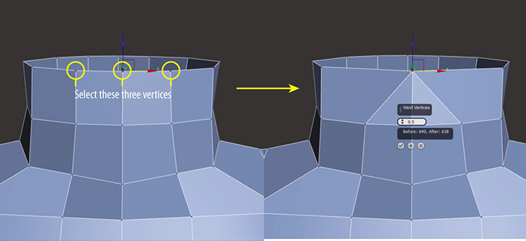
Figure 8-33: Select the three vertices at the top of the neck (left). Use the Merge tool to combine the vertices (right).
- Repeat the process on the row below the top row. Then repeat on the row below that until you get to the fourth row down, as shown in Figure 8-34.
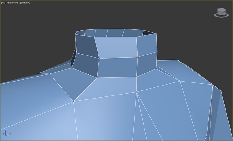
Figure 8-34: The merged vertices on the front of the neck
- Repeat the process for the back of the neck.
- 12. Choose Geometry (All) ⇒ Attach; then select the head.
- Switch to Border mode, and select the border of the head and neck (hold down Ctrl to select both).
- In the Modeling tab ⇒ Borders ⇒ Bridge ⇒ Bridge Settings, keep most of the settings at the default but set Twist 1 to 1.
- There is still some twisting, so switch back to Vertex mode, and in the Edit tab of the modeling ribbon, use Constrain To Edge to help in moving the vertices, as shown in Figure 8-35.
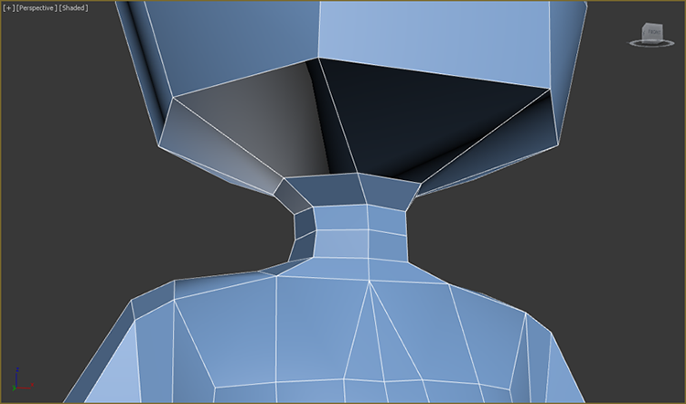
Figure 8-35: Move the vertices at the neck to eliminate the twisting.
There is one more thing that you can do; hidden in the file is an eyeball. Just right-click in the viewport and from the context menu choose Unhide All. If you are using your own file, just merge the c08_ex9_eye.max file from the c08_CharacterModeling project folder. Save the file you are working with. To check your work open the c08_ex9_head_end.max scene file in the scenes folder of the c08_CharacterModel project. Turn on Use NURMS to see the final model at its smoothed-out best, as shown in Figure 8-36.
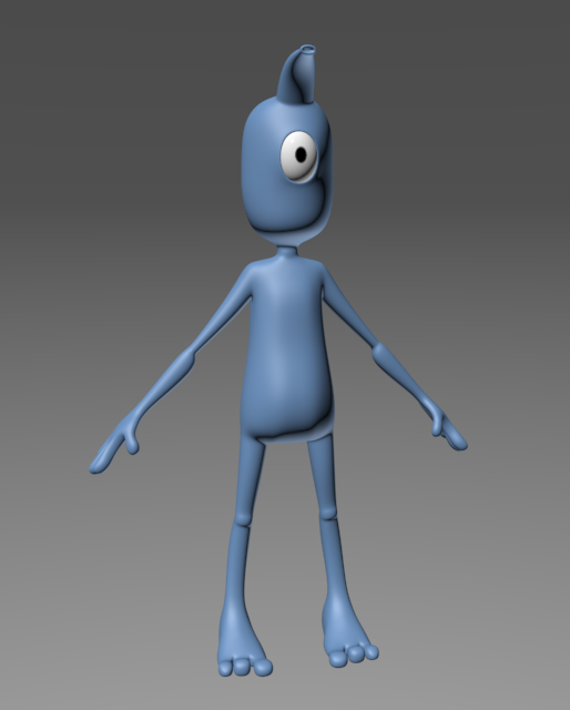
Figure 8-36: The completed alien model