
Chapter 2
Your First 3ds Max Project
In production work, setting down a plan and having clear goals for your project is very important. Without a good idea of where you need to go, you’ll end up floundering and losing out on the whole experience. In any project, the beginning of the workflow starts with modeling.
Modeling in 3D programs is like sculpting or carpentry; you create objects out of shapes and forms. Even a complex model is just an amalgam of simpler parts or shapes/volumes. The successful modeler can dissect a form down to its components and translate them into surfaces and meshes. The Autodesk® 3ds Max® modeling tools are incredibly strong for polygonal modeling, so the focus of the modeling in this book is on polygonal modeling. In this chapter, you will learn modeling concepts and how to use 3ds Max modeling toolsets.
In this chapter, you will learn to:
- Set up a project workflow
- Model accurately using reference material
- Build a simple model
- Create details using splines
- Create 3D from 2D using lathing, extruding, and beveling
Set Up a Project Workflow
You will begin by modeling a clock body to develop your modeling muscles. This exercise introduces you to primitives and polygons. You will be modeling by editing the polygon component; it’s called editable-poly modeling. Why buy a clock when you can just make one using 3ds Max tools?
Exercise 2.1: How to Set a Project
Download the c02_First Project, c02_First Project.zip, from the book’s web page at www.sybex.com/go/3dsmax2015essentials. Place the files on your hard drive. Open the 3ds Max 2015 program and set a 3ds Max project. Choose the c02_First Project folder from your hard drive, flash, or network drive and follow these steps:
- Set your project folder to the
c02_First Projectyou just downloaded (click the Application button ( ) and choose Manage ⇒ Set Project Folder).
 - Navigate to the place on the hard drive where you saved the book projects.
- Click
c02_First Project, and then click OK.
Now when you want to open a scene file, just click the Application button and choose Open, and you will automatically be in the c02_First Project scenes folder.
The Secret to Accurate Modeling: Reference Material!
Using reference materials will help you efficiently create your 3D model and achieve a good likeness in your end result. The temptation to just wing it and start building the objects is strong, especially when time is short and you’re raring to go. You should always suppress this temptation in deference to a well-thought-out approach to the task. Sketches, photographs, and drawings can all be used as resources for the modeling process. Not only are references useful for giving you a clear direction in which to head, but you can also use references directly in 3ds Max to help you model. Photos, especially those taken from different sides of the intended model, can be added to a scene as background images to help you shape your model.
Go to the c02_First Project folder on your hard drive; in the sceneassets/images subfolder you will see some additional reference images of the clock. These sample reference images will give you an idea of what kind of images will be useful for a project like the clock. Of course, if this were your clock, you would have captured tons of pictures already, right?
You’re so close to modeling something! You’ll want to get some sort of reference for what you’re modeling. Study the photo in Figure 2-1 for the model.

Figure 2-1: The clock to be modeled
Exercise 2.2: Setting Up the Modeling Reference
For the best in modeling references, bring in photos of your model and use the crossing boxes technique, which involves placing the reference images on crossing plane objects or thin boxes in the scene.
To begin the clock body, start with a new 3ds Max file:
- Open a new 3ds Max file by clicking the Application button (
 ) and choosing New. This clears the contents of the current scene without changing any of the system settings.
 - On the Create tab (
 ), click the Geometry icon (
 ), and in the Object Type drop-down menu, click the Plane button.
 - Make sure the Front viewport is selected by right-clicking it. This will align the plane to that viewport when it is created.
- In the plane primitive parameters, expand the Keyboard Entry rollout.
- Change the value in the X Position Type-In box to 0.0, the Y box to -3.0, and the Z box to 0.0, as shown in Figure 2-2. This will place the plane 5 units away from the center of the scene along the Y-axis.
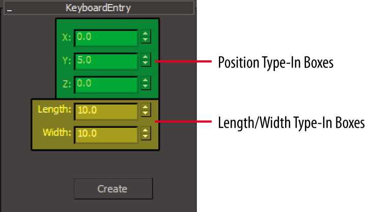
Figure 2-2: Position and Length/Width Type-Ins in the plane Keyboard Entry rollout
- Change Length value to 10 and the Width value to 10, and then click the Create button (
 ). This creates the image plane in the Front viewport, which you will use for the front view image plane.
- Change the name of the Plane001 object to Front View Image.
- Now right-click the Left viewport to activate it. Back in the Standard Primitives drop-down menu, select the Plane button, if it is not already active from the previous steps. Expand the Keyboard Entry rollout.
- Change the X Position Type-In to 0.0, Y to 0.0, and Z to 0.0. This will move the plane to the center and help with the alignment of the images when they are in place.
- Change the Length parameter in the Keyboard Entry to 10 and the Width parameter to 10, if they are not already set that way. The parameters will stay set from the previous plane that was created.
- Click the Create button in the Keyboard Entry rollout.
- Rename the Plane001 object Side View Image.
- Go to the Viewport Label menus at the top left of the Left viewport. Click the Shading viewport label menu and choose Shaded, as shown in Figure 2-3.
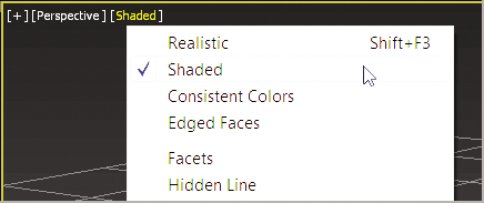
Figure 2-3: Shading viewport label menu
- Do the same for the Front viewport.
- Open a Windows Explorer window; navigate to the
sceneassetsimagesfolder in thec02_First Projectfolder that you downloaded to your hard drive. In this folder, you will find two reference JPEG images, one for each of the two image planes you just created in the scene. - Select the front view reference image called
Front.jpg, drag it into the Front viewport, and then drop it onto the Front View Image plane. This automatically places the image onto the plane, so the image is viewable in the viewport. - Repeat the previous step to place the
Side.jpgimage onto the Side View Image plane in the Left viewport. Figure 2-4 shows the image planes with the reference images applied.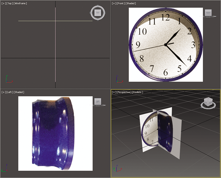
Figure 2-4: The image planes with the clock images applied
- To finish, click the Application button (
 ) and choose Save As. Save the file; to check the progress of your work against our example, you can open
 c02_ex2_ref_end.max.
Building a Simple Model
When modeling any object, it is always best to study the object and break it up into smaller, easier-to-model components. To begin modeling the clock body, you will start with a cylinder because the clock body has a cylindrical shape as its base.
Exercise 2.3: Start with a Primitive
For this procedure, either continue with a file from a previous exercise or use the c02_ex3_body_start.max file. Follow these steps:
- Select the Front viewport, which should still be set to Shaded display mode, from the previous steps.
- Enable Edged Faces mode in the viewport by using the keyboard shortcut F4, if it isn’t already set. Edged Faces places the wireframe over the shaded object, making the object easier to see when modeling.
- Right-click the Front viewport to make it the active viewport. This will align the cylinder to the Front viewport when it is created.
- In the command panel, choose the Create tab, click the Geometry icon, and make sure Standard Primitives is selected.
- In the Object Type rollout, click Cylinder, and select the Keyboard Entry rollout to expand the parameters.
- Leave the X, Y, and Z values at 0, but enter 5.0 for Radius and –5.0 for Height, and then click the Create button.
- Open the Modify panel (
 ); this is where you go to edit the parameters of an object.
 - Change Height Segments to 1 and Sides to 30; then press Enter on your keyboard to set the new parameter. Leave all the remaining parameters at the default.
- To turn on See-Through mode, use the keyboard shortcut Alt+X. See-Through mode will ghost out the cylinder and allow you to see through it to the image planes.
Save the file and to check the progress of your work against our example, open c02_ex3_body_end.max.
Exercise 2.4: Modeling in Sub-Object Mode
To start the process of modeling the clock, you need to access the cylinder’s components. All 3D objects are at their core made up of three main components: vertices, edges, and polygons. These components are the basis of polygon modeling. To access the components of any object, you need to convert it to an editable poly, which means a polygon that allows access to the components. There are many ways to do this; we will be using the Graphite Modeling Tools set, also called the ribbon. For this procedure, use the c02_ex4_body_start.max file or the file that you saved in the previous section. Follow these steps:
- Select the cylinder; go to the Ribbon ⇒ Modeling tab ⇒ Polygon Modeling select the Convert to Poly button, as shown in Figure 2-5.
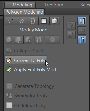
Figure 2-5: Converting the cylinder to an editable poly
- Turn on Edged Faces in the Front, Left, and Perspective viewports using the keyboard shortcut F4, if it isn’t already enabled. This will allow you to see the wireframe while modeling.
- Select the Polygon icon (
 ) or press 4 on the keyboard to enter the Polygon sub-object mode.
 - In the Perspective viewport, orbit around the cylinder so you can see the back end. Do this by clicking and dragging on any part of the ViewCube, which is the icon in the upper right of the viewport. If the Front View Image is in the way, select it, and then right-click it and choose Hide Selected.
- Then select the back-end polygon. The polygon is shaded red to indicate it is selected, as shown in Figure 2-6. (Front viewport image plane is hidden in the figure.)
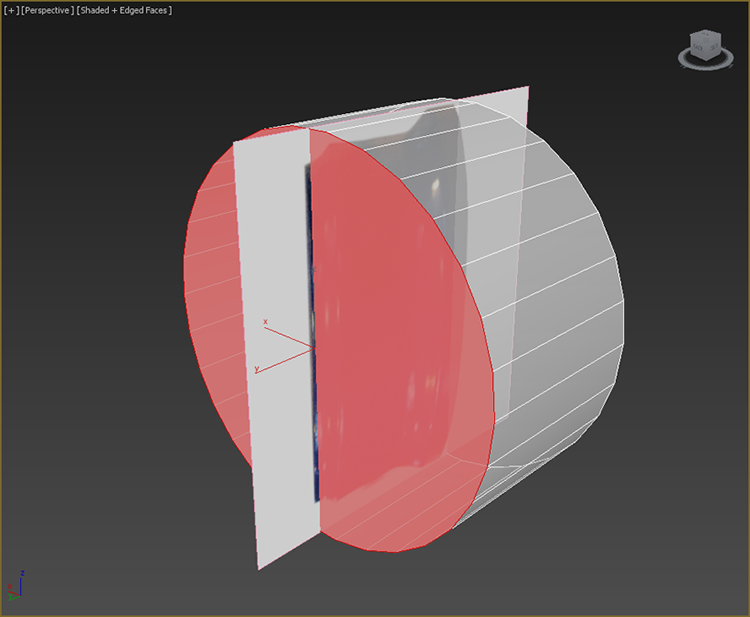
Figure 2-6: Select the back polygon of the cylinder; it is shaded red when selected.
- In the Ribbon ⇒ Modeling tab, go to the Polygons panel and click Outline. Click the arrow under the Outline button, and then select Outline Settings. This will open the Outline caddy, which is a dialog box to input your outline parameters.
- Change Outline Amount to –0.75, and click the OK button (
 ). This will scale the selected polygon smaller. Look at the cylinder in the Left viewport. You will see that end of the cylinder now fits that end of the clock on the image plane.
 - In the Ribbon ⇒ Modeling tab, go to the Edit panel and select the SwiftLoop tool. You will add three new subdivisions, or loops, on the cylinder. To add the loops, just move your cursor over the part of the cylinder and you will see a preview loop. When the preview is where you want it, just click, and the new loop will be created.
- View the cylinder in the Left viewport; place the loops at the positions shown in Figure 2-7. With the new loops (or edge loops) in place, you will now edit them to change the profile of the cylinder to match the clock body.
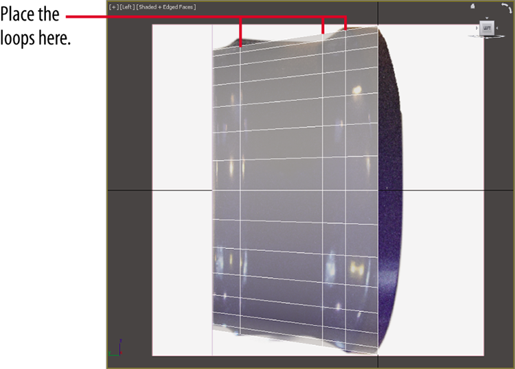
Figure 2-7: Using the SwiftLoop tool, place three loops as shown.
- In the Ribbon ⇒ Modeling tab ⇒ Modeling, select Edge mode (keyboard shortcut 2). When you select Edge mode, the last loop you created will be selected. If it is not selected, continue with the steps 11 and 12; if it is selected, skip to step 13.
- Select one of the edges toward the top of the cylinder; only a single edge will be selected, not the entire loop.
- On the Modify Selection tab of the Ribbon ⇒ Modeling tab, select Loop. This will continue the selection around the cylinder. For a shortcut for the Loop tool, double-click an edge and the loop will be competed.
- Move your cursor to the main toolbar and select the Scale tool (
 ). The keyboard shortcut is R.
 - The triangle in the center of the Scale gizmo will turn yellow when active. Scale the edges up until they match the detail in the Left viewport image plane.
- Repeat steps 11 through 14 on the other new edge loops until the cylinder matches Figure 2-8. Don’t worry if it doesn’t match up perfectly with the image.
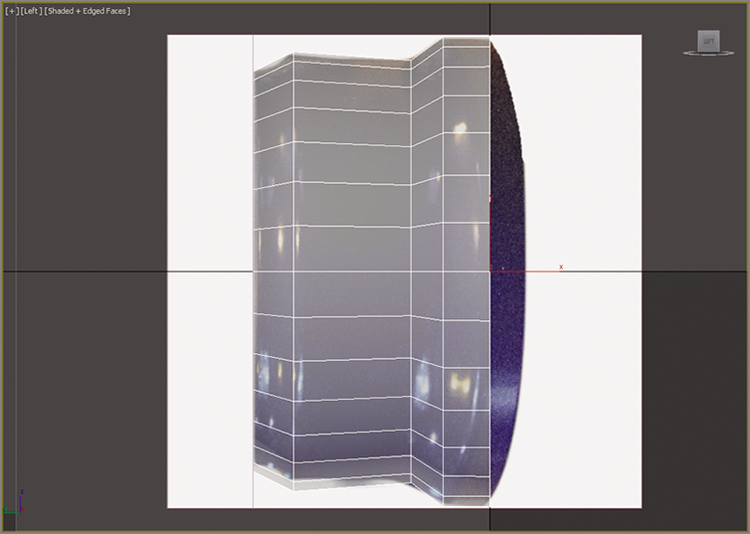
Figure 2-8: Edges are scaled to match the image plane.
- This is a good time to save your file. Choose Save from the Application menu. You will use this file in the next section.
Save the file and to check the progress of your work against our example, open
c02_ex4_body_end.max.
Exercise 2.5: Bring on the Bevel
Now you will add detail to the front of the clock. On the Clock object there is a small edge and a depression where the clock face and hands sit. To create this edge in the cylinder, you will use the Bevel tool. Beveling involves first extruding polygons and then scaling the extruded polygons with the Outline tool. The Bevel tool has three parameters:
- Bevel Type Controls how to extrude multiple polygons at once.
- Height Specifies how much extrusion to apply, based on units.
- Outline Amount Scales the outer border of the selected polygons, depending on whether the value is positive or negative.
For the Clock object the Bevel tool creates many of the details of the body. It allows you to create a rough model that you can refine with further tools. For this procedure, use the c02_ex5_body_start.max file or the file that you saved in the previous section. Follow these steps:
- Select the Polygon icon (
 ), or use the keyboard shortcut 4 to enter the Polygon sub-object mode.
 - Select the front face of the cylinder.
- On the Polygons panel in the ribbon, click the arrow next to the Bevel button. Then select Bevel Settings, as shown in Figure 2-9. This will open the Bevel caddy, which is a dialog box for inputting your bevel parameters.
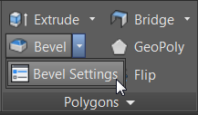
Figure 2-9: Bevel Settings will bring up the caddy for parameter input.
- In the Bevel caddy, enter the 0.0 in the Height text box, and then press Enter on your keyboard.
- Enter –0.25 in the Outline text box and press Enter again.
- Click the Apply and Continue button (
 ). This applies the specified settings without closing the caddy.
 - Now change the Bevel caddy parameters. Enter –1.0 in the Height box, press Enter, enter 0.0 in the Outline box, press Enter again, and then click the OK button.
The detail that you just created will be the part of the clock body where the clock face will sit. Figure 2-10 shows the clock the way it looks with the changes, shown with image planes hidden and See-Through mode turned off.
Save your file; to check the progress of your work open
c02_ex5_body_end.max.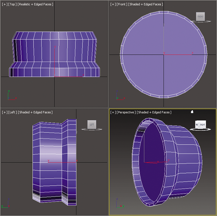
Figure 2-10: Clock body progress
Exercise 2.6: Chamfer Time
Chamfering refers to the rounding of sharp edges or corners. For the clock, the new details on the sides are too sharp. You will be using the Chamfer tool in Edge mode. For this section, you will turn off See-Through mode and hide the image planes. Use the c02_ex6_body_start.max file or the file that you saved in the previous section, and follow these steps:
- Select the clock body; then turn off See-Through mode, using the keyboard shortcut Alt+X. To hide the image planes, you will enter Isolate Selection mode. At the bottom of the interface, below the timeline, is an icon of a light bulb (
 ). The keyboard shortcut is Alt+Q.
 - Either click the icon or use the shortcut to hide all but what is selected.
- In the ribbon, open the Polygon Modeling panel and select Edge mode (keyboard shortcut 2).
- Select the edge shown in Figure 2-11.
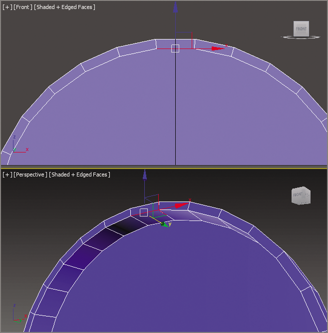
Figure 2-11: Select the edge shown in this image.
- In the Ribbon ⇒ Modeling tab ⇒ Modify Selection, select Loop. This will select the entire edge loop (or use the shortcut, which is to double-click the edge you want to loop).
- In the main toolbar, click the Select and Move tool (
 ). The keyboard shortcut is W.
 - Move the edges back toward the beveled surface, as shown in Figure 2-12.
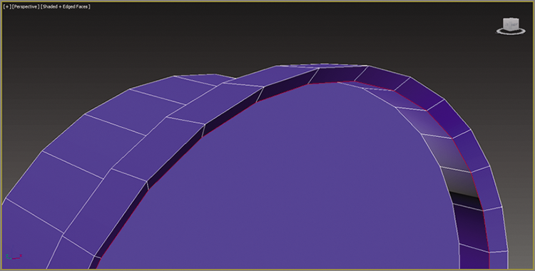
Figure 2-12: Move the edges back.
- Exit Edge mode by selecting the Ribbon ⇒ Modeling tab ⇒ Polygon Modeling ⇒ Edge (or use the keyboard shortcut 6). This will take you to the top level and out of sub-object mode. Now you want to turn See-Through mode back on.
- Select the clock body, and use the keyboard shortcut Alt+X to turn on See-Through mode.
- To exit Isolate Selection mode select the light bulb icon at the bottom of the interface. The image planes will reappear.
- On the Polygon Modeling panel in the modeling ribbon, select Edge mode (keyboard shortcut 2).
- Looking in the Left viewport, select and loop the middle edge, as shown in Figure 2-13 (the Ribbon ⇒ Modeling tab ⇒ Modeling ⇒ Modify Selection ⇒ Loop), to select the entire edge loop.
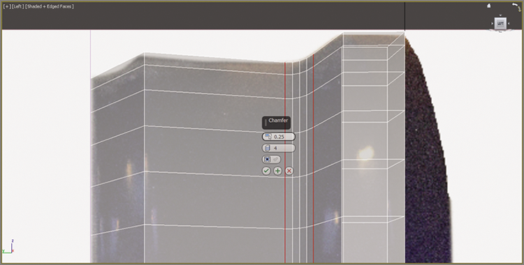
Figure 2-13: Select and loop the edge to prepare for chamfer.
- Go to the Ribbon ⇒ Modeling tab ⇒ Edges ⇒ Chamfer, and click the arrow under the Chamfer button; then select Chamfer Settings. This will open the Chamfer caddy.
- To Create the smooth curve from the sharp edges input 0.25 for Edge Chamfer Amount (don’t forget to press Enter on keyboard!) and 4 for Connect Edge Segments, and again press Enter.
- Then click OK (
 ). The results are shown in Figure 2-14.
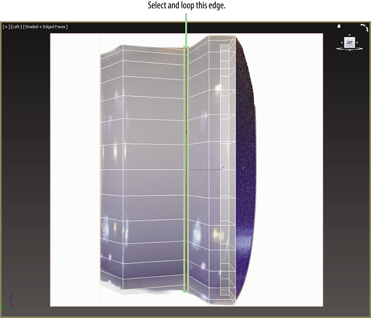
Figure 2-14: The chamfer performed on a looped edge
- On the front face of the clock, select an edge on the lip (where the clock face will be). Then hold the Ctrl key and select three more edges going toward the back of the clock, as shown in Figure 2-15 (which has See-Through mode turned off with shortcut Alt+X).
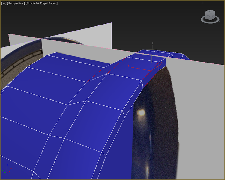
Figure 2-15: Select these four edges.
- Loop the edges (the Ribbon ⇒ Modeling tab ⇒ Modify Selection ⇒ Loop).
- Go to the Ribbon ⇒ Modeling tab ⇒ Edges ⇒ Chamfer, and click the arrow under the Chamfer button; then select Chamfer Settings. This will open the Chamfer caddy.
- To create the smooth curve from the sharp edges, enter 0.05 in the Edge Chamfer Amount text box, and press Enter; then enter 2 in the Connect Edge Segments box and press Enter again.
- Click OK (
 ). The results are shown in Figure 2-16. The back side of the clock needs some special attention; its detail is a bit more intricate. First, another SwiftLoop needs to be added, and then both edges need to be chamfered. Make sure you are still in Edge mode. If you are not, select Edge or the use the keyboard shortcut 2.
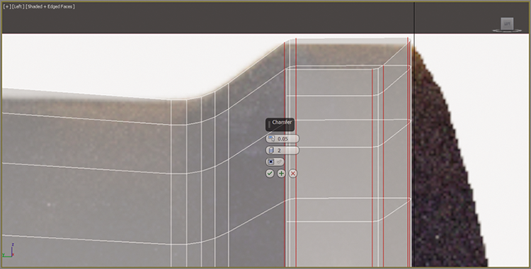
Figure 2-16: Chamfer result for the clock body’s edge and lip.
- In the Ribbon ⇒ Modeling tab ⇒ Edit, and select the SwiftLoop tool.
- Add a SwiftLoop between the back edge of the clock and the loop that was added earlier, as shown in Figure 2-17.
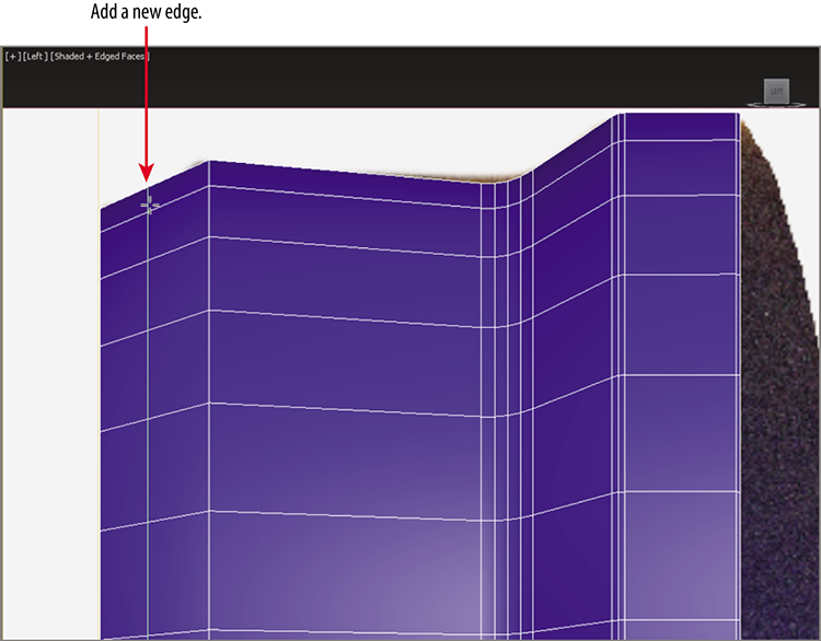
Figure 2-17: Add an edge loop with SwiftLoop.
- In the main toolbar, select the Select and Uniform Scale tool (R), and scale down the edge loop until it matches the size in the image plane.
- Hold down Ctrl and click one of the edges to the right of the new edge you just created.
- Select the Ribbon ⇒ Modeling tab ⇒ Modify Selection panel ⇒ Loop; this will select that loop also.
- Select the Ribbon ⇒ Modeling tab ⇒ Edges panel ⇒ Chamfer. Click the arrow under the Chamfer button, and then select Chamfer Settings; this will open the Chamfer caddy.
- Enter 0.1 in the Edge Chamfer Amount text box and 3 in the Connect Edge Segments box. Then click OK; the results are shown in Figure 2-18.
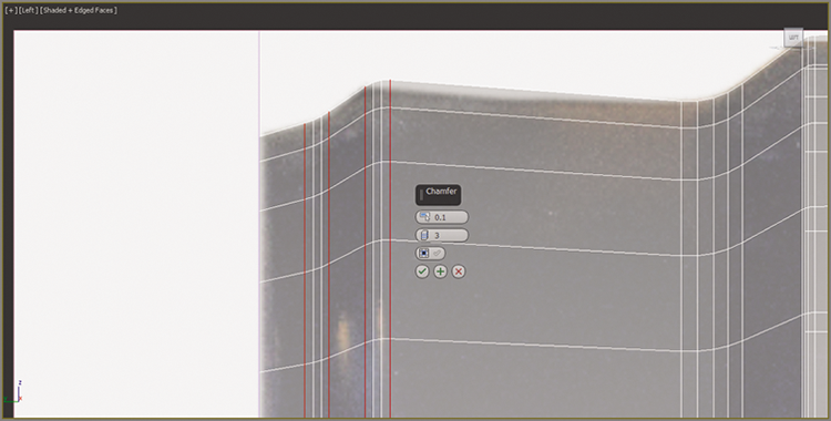
Figure 2-18: The two edge loops chamfered
- To finish this section, select the cylinder and change the name to Clock Body.
- Toggle See-Through mode off (Alt+X).
- Save your file, and to check your progress open
c02_ex6_body_end.max.
Creating Details Using Splines
Now that the clock body is complete, it’s time to move on to some of the clock parts. The parts that will be covered in this section are the handle, the hands, and the bell. To create these objects, you will learn a modeling technique called spline modeling. In computer graphics, a spline is a group of vertices and connecting segments that form a line or curve. Splines are used to create more complex geometry than can be found in the primitives available in 3ds Max. The first clock part that you will create is the clock handle, shown in Figure 2-19.

Figure 2-19: The clock handle
Exercise 2.7: Building the Handle
Follow these steps:
- Open
c02_ex7_handle_start.maxfrom thescenesfolder of theClockproject on this book’s companion web page. This file has a full image of the front of the clock, loaded onto an image plane. - Start by accessing the Create panel (
 ), and choose the second icon from the row of icons, Shapes (
 ), and from there choose Line.
The following apply when you use the Line tool:
- A single click in a viewport creates a point with a linear segment.
- A click and drag creates a curved segment when you let go of the mouse.
- Holding the Shift key will constrain your movement to 90-degree angles; this can be very helpful in creating straight lines.
- A right-click exits the Line command.
Creating a line using this method can be difficult; it is easier to start with a simple shape and add more detail later. Figure 2-20 shows a simplified line that represents the clock handle.
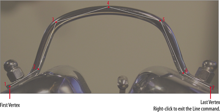
Figure 2-20: The intended cross section for the clock handle.
- In the Front viewport, click to set a vertex and let go (refer to the first vertex in Figure 2-20).
- Continue to click and move, following the handle around until you reach the seventh vertex; then right-click to exit the Line command. Now that the rough line is finished, it needs to be smoothed out and refined.
- With the line selected, in the Modify panel’s modifier stack, click the plus sign (+) to expand the list of sub-objects.
- Select Vertex, as shown in Figure 2-21.
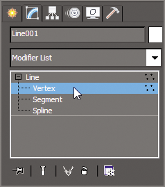
Figure 2-21: From the three sub-objects of the Line command, select Vertex.
- In the Front viewport, right-click the middle vertex.
- In the upper-left quadrant of the quad menu, choose Bezier, as shown in Figure 2-22.
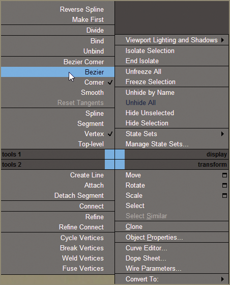
Figure 2-22: Use the quad menu to modify the vertex type.
- Choose the Select and Move tool (W), and then grab one of the green boxes on either side of the vertex at the end of the tangent handle, and move it until the curve matches the handle in the image plane.
- Right-click the selected vertices and change their vertex type to Bezier.
- Adjust the tangent handles to smooth out the remaining vertices on the spline except the first and last, as shown in Figure 2-23.
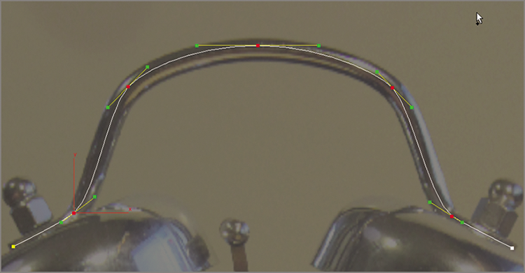
Figure 2-23: The line for the handle with all but the first and last vertices adjusted
- In the Rendering rollout in the Modify panel, check the boxes Enable In Renderer and Enable In Viewport.
- Change Thickness to 0.35 and leave the rest at the default, as shown in Figure 2-24.
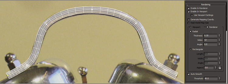
Figure 2-24: Rendering enabled on the clock handle line, set to Radial
- Use See-Through mode (Alt+X) to ghost out the handle model; this will allow you to see the clock on the image plane.
- In the Ribbon ⇒ Modeling tab, open the Polygon Modeling panel and choose Convert to Poly. This will keep the radial thickness and allow for component manipulations.
- Click the Select Object tool (
 ) (Q) and switch to Vertex mode. The handle has the correct shape, but the area where the handle is between the bell and the bolt needs to be scaled down.
 - To make this simpler, in the main toolbar, click and hold down the Rectangular Selection Region tool; this will bring up a flyout.
- Choose the Fence Selection Region, as shown in Figure 2-25.
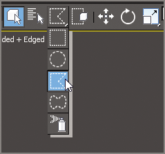
Figure 2-25: On the Selection Region flyout, choose the Fence Selection Region.
- Drag a custom selection from the end of the handle line past the seventh row of vertices, as shown in Figure 2-26. To close the selection, click the part of the selection where you started.
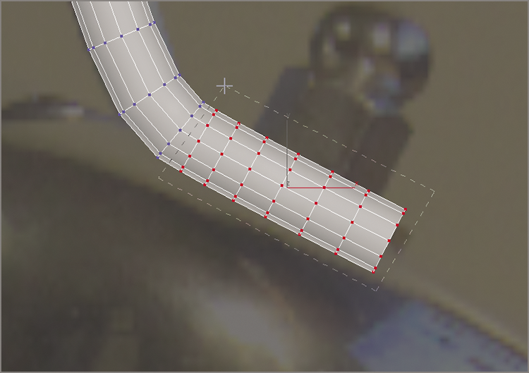
Figure 2-26: Use the Fence Selection Region to draw a selection around the desired vertices.
- Select the Select and Scale tool (R). In the main toolbar, to the right of the Scale tool is the Reference Coordinate System drop-down menu.
- Click the arrow and choose Local from the list.
- Move your cursor over the Y-axis of the Scale gizmo. Scale the vertices down until they match the image.
- Continue selecting and scaling vertices until they match the image. Use the Select and Move tool if necessary.
- Exit Vertex mode and then repeat the same process on the left side of the handle, as shown in Figure 2-27. When finished, name the object Handle.
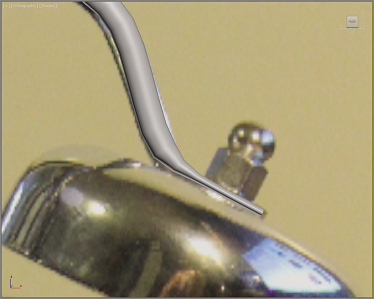
Figure 2-27: The finished handle
- Time to save the file, but this time choose Save As and name the file
Clock_Handle_End.max. To check your progress, openc02_ex7_handle_end.max.
Lathing, Extruding, and Beveling to Create 3D from 2D
Now that the body of the clock and the handle are done, it’s time to make the bells. You will use splines and a few surface creation tools that are new to your workflow. You are going to create a profile of the bell and then rotate the profile around its axis to form a surface. This technique is known as lathe, not to be mistaken for latte, which is a whole different deal and not covered in this book.
Exercise 2.8: Lathe to Make a Whole
Open c02_ex8_bell_start.max from the scenes folder of the Clock project on the companion web page. You are going to create a cross section of the bell. To build the bell, follow these steps:
- Select Create ⇒ Shapes ⇒ Line. Figure 2-28 shows the cross section with the vertices numbered according to their creation order.
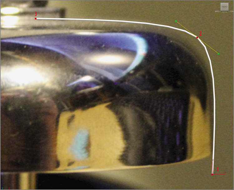
Figure 2-28: The bell’s profile line with the vertices numbered according to their creation order
- Starting at the bottom-right side of the bell image, click and let go of the mouse. This will create the first vertex as a corner (1).
- Now move the mouse up where the bell curves and drag out a tangent to create a Bezier vertex (2).
- Continue the drag until the line’s curve follows the bell image.
- Again, move the mouse to the left and to the middle of the bell, and click to create a corner vertex (3).
- Right-click to end the Line tool. The profile should match Figure 2-28.
- On the Modify panel, choose Lathe from the Modifier List, as shown in Figure 2-29.
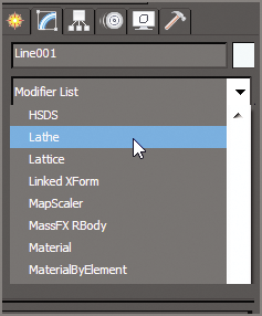
Figure 2-29: Choose the Lathe modifier from the Modifier List.
- To reposition the center of the lathe, open the Lathe Parameters rollout, and in the Align area, click Min. This should change the lathe to look more like a bell, as shown in Figure 2-30.
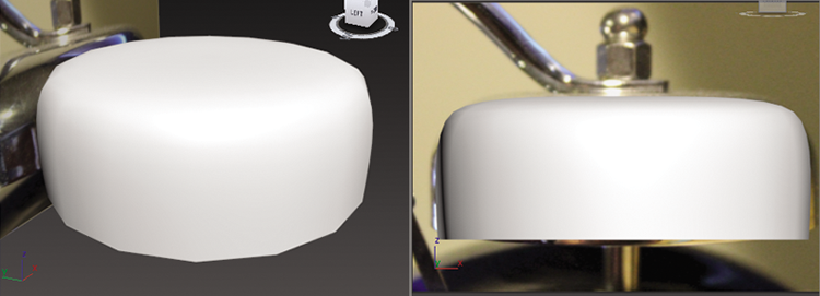
Figure 2-30: The bell with the lathe center in the correct place
- To finish the bell, create a cylinder to represent its base post. Then create another cylinder to represent a bolt above the bell and a sphere for the ball at the top, as shown in Figure 2-31 and Figure 2-32. Now that all the separate pieces are created, it’s time to put them together.
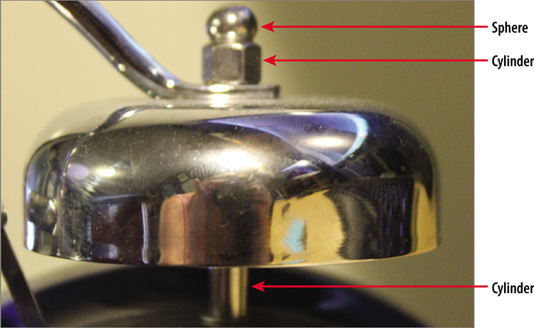
Figure 2-31: The image of the bell showing the three pieces to be created
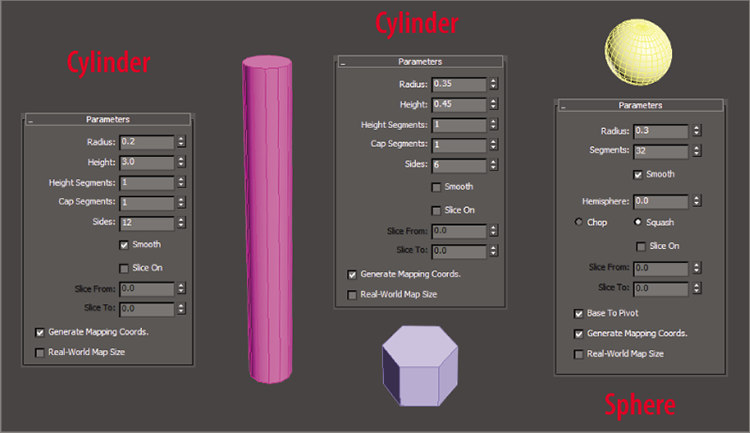
Figure 2-32: The parameters for the three objects to be created
- Using the Move and Rotate tools, reference Figure 2-31 for placement of objects. Leave a gap where the handle goes.
- Then select all the separate pieces, including the Bell object. It needs to be oriented so it fits on the clock body, which means it needs to be rotated as a whole.
- From the Main toolbar, select Group ⇒ Group, as shown in Figure 2-33, and then name the group Bell.
- Select each object and name it appropriately.
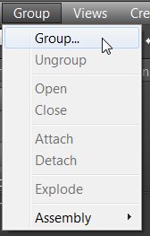
Figure 2-33: In the Group menu, choose Group and name the group Bell.
- Save the file as
c02_Bell_End.maxand use it for the next section. To check your progress, openc02_ex8_bell_end.max.
The next step in the process is to make the clock face by creating the hour hand, the minute hand, and the second hand. This could be done by creating an image of a clock face in a graphics program like Photoshop and then applying that image as a surface onto the 3D Clock object. For this exercise, you will be creating the clock face elements—the numbers and hands—as 3D objects, using another set of modifiers, Extrude and Bevel. The Extrude modifier adds depth to a shape—that’s it. It’s simple and incredibly useful. The Bevel modifier also adds depth to a shape but allows you to add a round bevel to the edges.
Exercise 2.9: Creating the Clock Numbers and Hands
Load c02_ex9_face_start.max from the scenes folder of the Clock project on the companion web page or use the file you have been working with. To create the clock numbers, follow these steps:
- Start in the Create panel ⇒ Shapes ⇒ Text. Before you create the text shape, set up the text parameters.
- Select the typeface down arrow next to the font name in the Parameters rollout.
- Choose Times New Roman. If you do not have that typeface, just choose whichever font you desire.
- Change Size to 1.45.
- In the Text Type-In box, type 12. All parameters should match Figure 2-34.
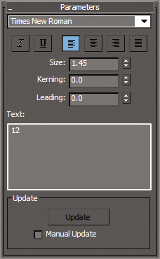
Figure 2-34: Text shape parameters
- Move the mouse into the viewport over the number 12 on the image of the clock face, and then click.
- Now open the Modify panel, and in the Modifier List, click Bevel.
- In the Bevel Values rollout, change Level 1: Height to 0.01 and Outline to 0.01. This will extrude the 12 shape and taper the mesh wider at the top.
- Check the box next to Level 2 and change Height to 0.01; leave Outline at 0.0.
- Check the box next to Level 3 and change Height to 0.01; set Outline to -0.01.
- Match all bevel levels to those in Figure 2-35.
- Now in the Parameters rollout in the Surface group, select Curved Sides.
- Change Segments to 2, and check the box next to Smooth Across Levels, as shown in Figure 2-36. This will give the 12 rounded smooth sides.
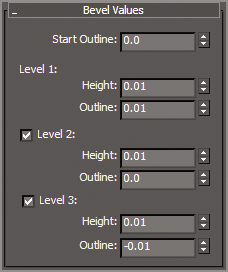
Figure 2-35: Bevel Values rollout showing all of the shape parameters for the number 12
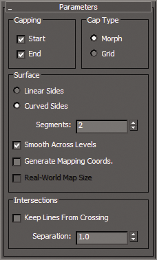
Figure 2-36: Parameters rollout for the bevel modifier
- At the top of the Modify panel, change the name to 12, click the color swatch next to the Name (text field) Type-In, and choose black. Select OK. Figure 2-37 shows the results of the Bevel modifier. Move the number into place over the number in the image plane.
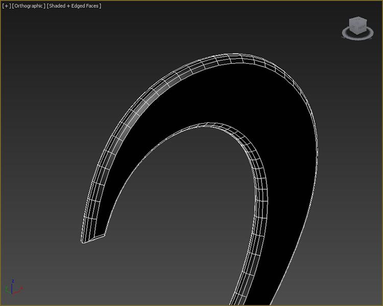
Figure 2-37: Bevel modifier applied to the number
- To create the remaining numbers, select Create ⇒ Shapes ⇒ Text and place the cursor over the number 1.
- Add the Bevel modifier; the same parameters you used for the number 12 will be repeated. This makes it easy to finish off the rest of the clock numbers.
- Repeat steps 15 and 16 for each number on the clock face. Then name each new number, and change the color to black.
- Select all the numbers by holding Ctrl and clicking each.
- Then choose Group from the Group menu, as you did with the Bell object.
- Name the group Numbers.
Follow these steps to create the clock hands:
- Select the Create panel ⇒ Shapes ⇒ Rectangle. Create a rectangle over the minute-hand image.
- Back in the Create panel, uncheck the box next to Start New Shape. This will allow you to create a second piece that is connected to the rectangle.
- Select Circle and create a circle over the circle base of the minute hand.
- Open the Modify panel, and in the modifier stack, in the Selection rollout, select Vertex mode (
 ).
).
- In the Geometry rollout, select Refine and click each side of the rectangle in the middle, as shown in Figure 2-38.
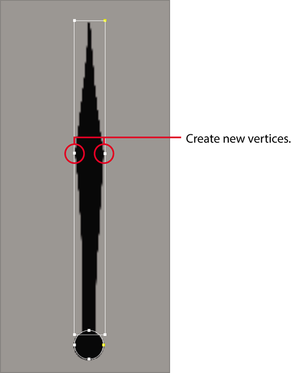
Figure 2-38: Use Refine to add two vertices to the right and left sides of the rectangle.
- Select and move the vertices on the top of the rectangle so they come to a point. Move the vertices on the bottom so they match the image of the minute hand in the viewport.
- Go to the Modify panel, and from the Modifier List, add the Extrude modifier.
- Change Amount to 0.025.
- Change the Name to Minute hand and the color to black.
- Repeat the same steps (1–10) on the hour hand. The second hand is even easier; just create a rectangle, make sure Start New Shape is still unchecked, and then create another rectangle.
- Move and rotate each clock hand into the position you see on the clock image shown in Figure 2-39.
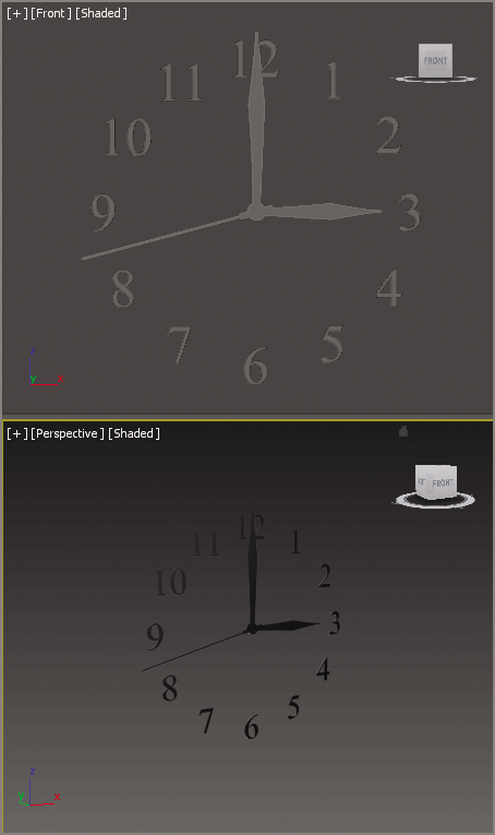
Figure 2-39: The clock hands positioned to match the clock face
Of course, you don’t have to position the hands exactly as they are shown in the image.
- When you have finished positioning the hands, save the file as
c02_Face_End.max. To check the progress of your work you can openc02_ex09_face_end.max.
Bringing It All Together
Most of the pieces are created for the clock. Now you just have to put it all together. Each piece was created in its own 3ds Max file. To bring them all together, you will use Merge. Merge allows you to bring into one scene different 3ds Max files. You can also just build all the parts to your model in a single 3ds Max file; we will look at that technique in later chapters.
Exercise 2.10: Using Merge
Follow these steps to merge all the parts:
- To begin, click the Application button and choose Reset. This will clear any data from previous work and reset the 3ds Max settings. Read the dialogs carefully; they might prompt you to save your previous file and to reset.
- Click the Application button, choose Import, and click Merge, as shown in Figure 2-40.
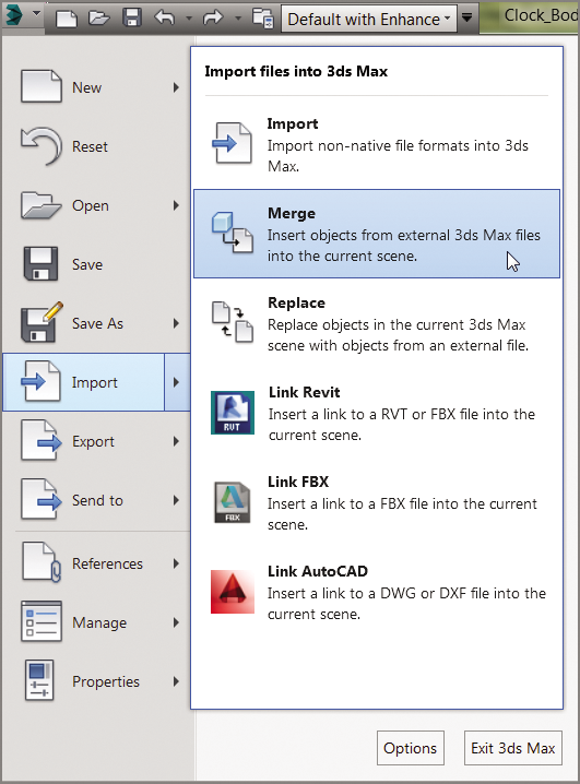
Figure 2-40: Merge is found in the Application menu under Import.
- Navigate to the
scenesfolder of the Clock project, and selectc02_ex6_body_end.max. Click Open. - From the list in the Merge dialog box, choose the Clock Body object and click OK to close the dialog box. In the new scene, the clock body will appear, located in the same spot as it was in the other 3ds Max file.
- Repeat the same steps for the handle, face, and bell scenes.
- Select the Bell group object, and from the Edit menu, choose Clone. This opens a Clone Options dialog box with clone options that are explained in more detail in the sidebar “The Clone Options Dialog Box.”
- Click OK to close the Clone Options dialog box, choose the Select And Move tool (W), and move the new Bell object to the other side of the clock body.
- Move and rotate the Bell group so it is positioned correctly on the clock body.
- The objects will need to be adjusted; use the transform tools and your best judgment. To check your progress you can open
c02_ex10_merge_end.max.
Still something missing? Well, this is where we leave you. With 90 percent done, it’s time to use the many tools you learned about in this chapter to finish the clock. All you have left to create are the clock feet and the bell hammer. Take a look at Figure 2-41 for an example of the finished clock to this point.
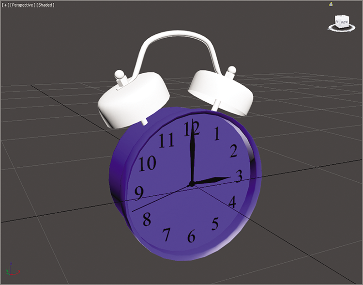
Figure 2-41: The clock so far