
Chapter 9
Introduction to Materials
A material defines an object’s look—its color, tactile texture, transparency, luminescence, glow, and so on. Mapping is the term used to describe how the materials are wrapped or projected onto the geometry (for example, adding wood grain to a wooden object). After you create your objects, the Autodesk® 3ds Max® program assigns a simple color to them, as you’ve already seen. You define a material by setting values for its parameters or by applying textures or maps. These parameters define the way an object will look when rendered. Much of an object’s appearance when rendered also depends on the lighting. In this chapter and in Chapter 13, “Introduction to Lighting: Interior Lighting,” you will discover that materials and lights work closely together.
In this chapter, you will learn to:
- Navigate the Slate Material Editor
- Identify the Standard material
- Identify the mental ray material
- Identify shaders
- Build materials for the couch
- Build materials for the lounge chair
- Build materials for the windows
Navigate the Slate Material Editor
The Material Editor is the central place where you do all of your material creation and editing. You can assign materials to any number of objects as well as have multiple materials assigned to different parts of the same object.
There are two interfaces to the Material Editor: the Slate Material Editor (or Slate) and the Compact Material Editor.
The Slate Material Editor is the interface you will use in this book: it is far superior to the Compact Material Editor and is especially nice when you are first learning mapping, because you can see the material structure, as shown in Figure 9-1.
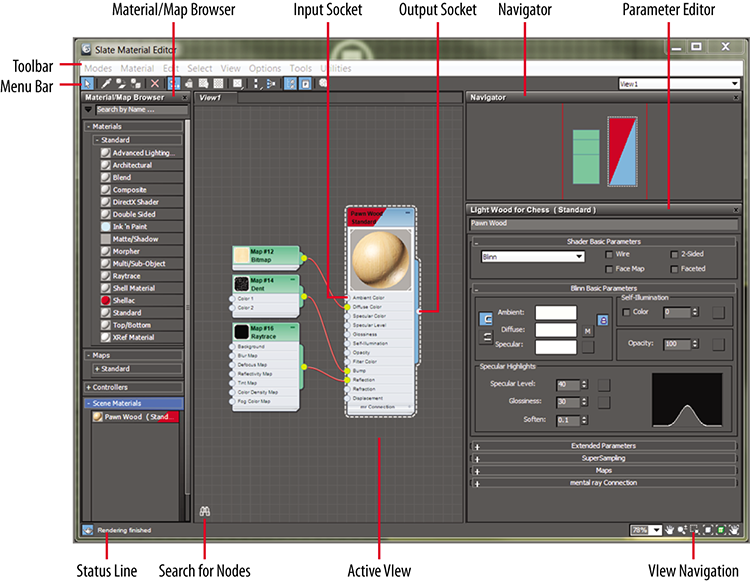
Figure 9-1: The Slate Material Editor
You can access the Slate Material Editor by choosing from the menu bar Rendering ⇒ Material Editor ⇒ Slate Material Editor. There is also an icon for it on the main toolbar (![]() ), and the keyboard shortcut to open the Slate Material Editor is the M key.
), and the keyboard shortcut to open the Slate Material Editor is the M key.
The Slate Material Editor has an interface that uses nodes and wiring to display the structure of materials. It has a simple and elegant layout with the Material/Map Browser on the left for choosing material and map types. The center area is the Active View area, where you build materials by connecting maps or controllers to material components. The area on the right is the Material Parameter Editor; within that area is a Navigator for moving within the Active View area.
Identify the Standard Material
Different materials have different uses. The Standard material is fine for most uses. However, when you require a more complex material, you can change the material type to one that will fit your needs. To change a material type in the Slate Material Editor, just choose from the list under Materials in the Material/Map Browser. You should see the rollout for Standard. If you are using the mental ray renderer, you will also see a rollout for mental ray and MetaSL. As you can see, the list is extensive; there are not enough pages in this book to cover the multitude of material types, so we will touch on some of the best for an introduction. You will also see some examples using the Slate Material Editor.
Standard Materials
Standard materials typically use a four-color model to simulate a surface of a single color reflecting many colors. The four colors are known as the material’s color components. Ambient color appears where the surface is in shadow, diffuse color appears where light falls directly on the surface, specular color appears in highlights, and filter color appears as light shining through an object. Along with the color components, there are parameters that control highlights, transparency, and self-illumination. Some of these parameters are different depending on the shader you are using. With the Standard material, as shown in Figure 9-2, you can imitate just about any surface type you can imagine.
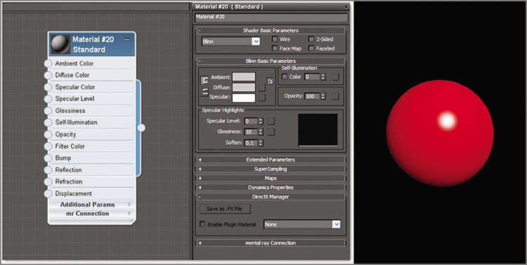
Figure 9-2: The Standard material type shown in the Slate Material Editor
Identify the mental ray Material
The 3ds Max comes with several materials created specifically for use with the mental ray renderer. These materials are visible in the Material/Map Browser when mental ray is the active renderer. For the sake of time and space, we are going to cover only one here, Arch & Design.
The mental ray Arch & Design material improves the image quality of architectural renderings. It improves workflow and performance in general and performance for glossy surfaces (such as floors) in particular.
Special features of the Arch & Design material include advanced options for reflectivity and transparency, ambient occlusion settings, and the ability to round off sharp corners and edges as a rendering effect. These material types will be explored further in Chapter 15, “mental ray.”
Identifying Shaders
The way light reflects from a surface defines that surface to your eye. With the 3ds Max program, you can control what kind of surface you work with by changing the shader type for a material. In either the Compact or Slate Material Editor, you will find the shader type in the material parameters in the Shader Basic Parameters rollout. This option will let you mimic different types of surfaces, such as dull wood, shiny paint, or metal. The following descriptions outline some of the shaders and the differences in how the shader types react to light, as shown in Figure 9-3.
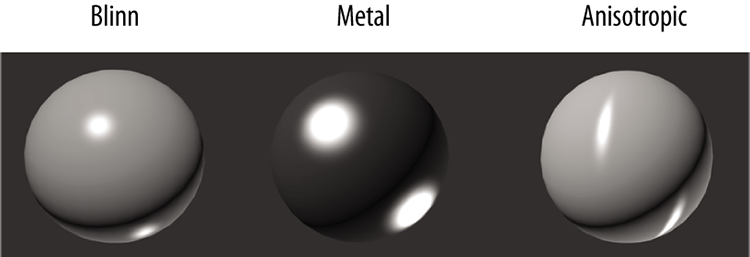
Figure 9-3: Shader types shown on rendered spheres
- Anisotropic Most of the surface types that you will see typically create rounded specular highlights that spread evenly across a surface. By contrast, anisotropic surfaces have properties that differ according to direction. This creates a specular highlight that is elliptical in shape and uneven across the surface, changing according to the direction you specify on the surface. The Anisotropic shader is good for surfaces such as foil wrappers or hair. There are extra controls for how the specular highlights will fall across the surface.
- Blinn This is the default shader because it is a general-purpose, flexible shader. The Blinn shader creates a smooth surface with some shininess. If you set the specular color to black, however, this shader will not display a specular highlight and will lose its shininess, making it perfect for regular dull surfaces, such as paper or an interior wall.
- Metal The Metal shader is not too different from the Blinn shader. Metal creates a lustrous metallic effect, with much the same controls as a Blinn shader but without the effect of any specular highlights.
- When you are first starting, it’s best to create most of your material looks with the Blinn shader until you’re at a point where Blinn simply cannot do what you need.
Build Materials for the Couch
Now let’s dive into creating material for the couch you modeled in Chapter 4, “Modeling in 3ds Max: Architectural Model Part II,” to get it ready for lighting and rendering in later chapters.
Study the full-color image of the couch shown in Chapter 4 in Figure 4-1. That will give you an idea of how the couch is to be textured. The couch’s material is basically all the same; once you create the material, it can be added to all the couch pieces.
Exercise 9.1: Creating a Standard Material
To begin, set the project to the c9_ArchMaterial project folder, and then open the c9_ex1_standard_start.max file from the scenes folder of the c9_ArchMaterial project folder downloaded from the book’s web page at www.sybex.com/go/3dsmax2015essentials. This file has the room with the lounge chair and couch set up. When you open this file, the couch is the only furniture visible; the other models have been hidden. Follow these steps:
- Open the Slate Material Editor (M). In the Material/Map Browser, open the Materials ⇒ Standard rollout, and double-click Standard. This will add the Standard material to the Active View area.
- Double-click the thumbnail with the sphere showing. This enlarges it and makes your material easier to view.
- Double-click again on the node title bar; this adds the node parameters to the Material Parameter Editor.
- In the Material Parameter Editor, at the top of the rollout, change the name to Gray/Green Woven Fabric.
- In the Blinn Basic Parameters rollout, select the color swatch next to Diffuse. This brings up the color selector.
- Set Red to 35, Green to 25, and Blue to 15. Click OK. In the material node, the sphere in the thumbnail will change color.
Save your file and move onto the next exercise. To check your work, open the c9_ex1_standard_end.max file from the scenes folder of the c9_ArchMaterial project folder.
Exercise 9.2: Applying the Material to the Couch
Continue with the file you are working on or open the c9_ex2_apply_start.max file from the scenes folder of the c9_ArchMaterial project folder. In the scene, select the couch. In Chapter 4, after the couch was merged into the room file, it was grouped. You can add materials to objects that are grouped; it can save time by applying the materials to all the pieces at the same time. You don’t want to do that, so with the Couch selected, follow these steps:
- On the menu bar, choose Group ⇒ Ungroup. Hold Alt on the keyboard and click on the couch feet to deselect them.
- Select the Gray/Green Woven Fabric material in the Material Editor; a white highlight appears around the material when it is selected. In the Slate Material Editor toolbar, click the Assign Material To Selection icon (
 ). When you compare the material in the viewport to the material on the couch, you should not see a difference, as shown in Figure 9-4, but the best way to view the material is by rendering the viewport.
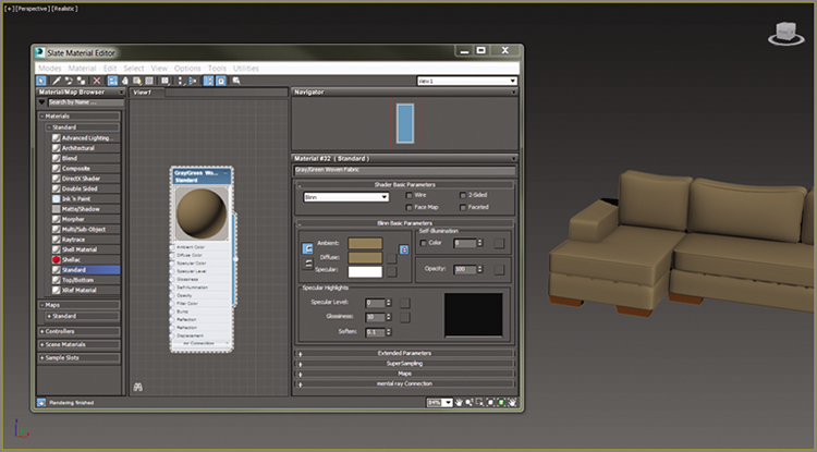
Figure 9-4: Material in the Material Editor and on the couch in the viewport
- In the Perspective viewport, use the keyboard shortcut Z to fit the couch model into the viewport. In the main toolbar, click the Render Production button (
 ), or press F9 for Render Last. The result is shown in Figure 9-5.
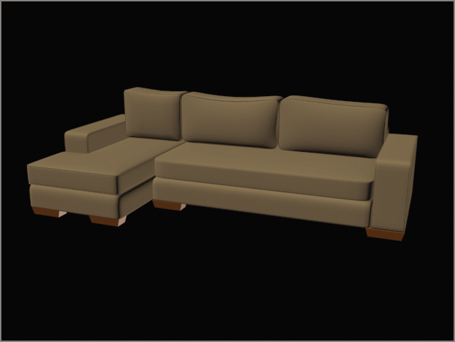
Figure 9-5: The render of the couch with a Standard material applied
Save your file and move on to the next exercise. To check your work, open the c9_ex2_apply_end.max file from the scenes folder of the c9_ArchMaterial project folder.
Exercise 9.3: Adding a Bitmap
The couch material needs some refinement. It looks flat and too perfect, which in this instance isn’t a good thing. A material with just color is not enough; what is needed is a map. Two map types are available, 2D and 3D:
- 2D maps are two-dimensional images that are mapped onto the surface of 3D objects; the simplest 2D maps are bitmaps (aka image files).
- 3D maps are patterns generated procedurally in three dimensions using the 3ds Max software.
Using a map to replace the diffuse color is a way to create a more realistic material because you are using actual images. Using maps in other material components can have various effects, such as making a material look bumpy and controlling its transparency. Continue with the file you are working on or open the c9_ex3_bitmap_start.max file from the scenes folder of the c9_ArchMaterial project folder.
- In the Slate Material Editor, open the Blinn Basic Parameters rollout and click the small gray box next to the Diffuse color swatch, as shown in Figure 9-6. This is a shortcut to the Diffuse Color Map in the Maps rollout, which you can find if you look lower in the Material Parameter Editor.
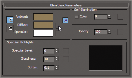
Figure 9-6: The shortcut button to add an image or bitmap to your material
- This brings up a separate Material/Map Browser; in the Maps ⇒ Standard rollout, choose Bitmap and click OK, as shown in Figure 9-7.
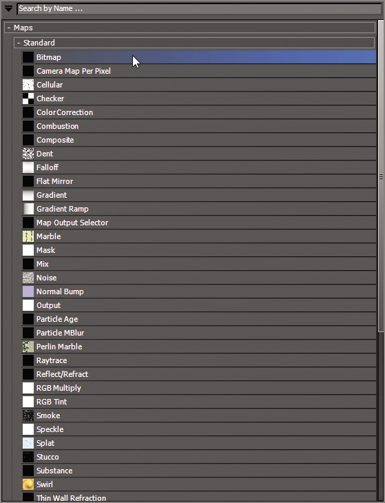
Figure 9-7: Choose Bitmap in the Material/Map Browser ⇒ Maps ⇒ Standard rollout to add an image to your material.
- In the Select Bitmap Image File dialog box, navigate to the
sceneassetsimagesfolder in thec9_ArchMaterialproject folder, select theGrayGreenWovenFabric.tifimage file, and click Open. - Select the bitmap node and then in the Slate Material Editor’s toolbar, click the Show Shaded Material in Viewport icon (
 ). In the viewport, the couch shows the fabric image applied, as shown in Figure 9-8. This improves the color and adds some color variations.
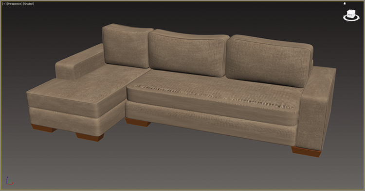
Figure 9-8: The couch with the fabric image applied
The image is projected onto the surface of the couch model. How the image looks on the model depends on what are known as mapping coordinates. Right now the bitmap doesn’t know how to lay on the surface, so it doesn’t look right. Save your file and move on to the next exercise. To check your work, open the c9_ex3_bitmap_end.max file from the scenes folder of the c9_ArchMaterial project folder.
Exercise 9.4: Mapping Coordinates
An image map is two-dimensional; it has length and width but no depth. 3ds Max geometry, however, extends in all three axes. Mapping coordinates define how and where image maps are projected onto an object’s surfaces and whether the maps are repeated across those surfaces.
Mapping coordinates can be applied to objects in several ways. When primitive objects are created and the Generate Mapping Coords option is checked at the bottom of the Parameters rollout, the appropriate mapping coordinates are created automatically. The next way is by applying a UVW Map modifier, which is commonly used to apply and control mapping coordinates. You select the type of mapping projection, regardless of the shape of the object, and then set the amount of tiling in the modifier’s parameters. The mapping coordinates applied through the UVW Map modifier override any other mapping coordinates applied to an object, and the Tiling values set for the modifier are multiplied by the Tiling value set in the assigned material.
You are going to use a modifier to replace those coordinates on the geometry. The UVW Map modifier allows you to change the bitmap by transforming the UVW Map modifier gizmo. Continue with the file you are working on or open the c9_ex4_mapping_start.max file from the scenes folder of the c9_ArchMaterial project folder.
- Select the main seat cushion on the couch, and enter Isolate Selection mode (
 ); the icon is under the timeline at the bottom of the interface (or press Alt+Q).
- In the Modify panel, select UVW Map from the Modifier List drop-down.
- Go to the UVW Map modifier parameters, and in the Mapping section, select Box for the projection type.
- In the Alignment section, click the Bitmap Fit button, as shown in Figure 9-9. This will take you to the Select Image dialog box.
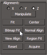
Figure 9-9: The Alignment section for the UVW Map modifier parameters
- Navigate to the
sceneassetsimagesfolder in thec9_ArchMaterialproject folder and select theGrayGreenWovenFabric.tiffile. Click Open. This will change the size of the UVW Map gizmo to the size and aspect of the image rather than the geometry. - In the modifier stack, click the plus sign in the black box next to the UVW Map modifier and select Gizmo.
- The box gizmo will turn yellow when in sub-object gizmo mode. You will now be able to transform the gizmo to the correct size.
- Switch to the Uniform Scale tool (
 ) or press R, and scale down the gizmo to 60 percent.
 - In the modifier stack, click the UVW Map modifier again to exit. Now that the couch fabric is where it should be, it is time to add the UVW Map modifier to the remaining pieces of the couch.
- Exit Isolate Selection mode.
- Switch to the Move tool, select one of the back couch cushions, and in the Modifier List, choose UVW Map modifier.
- In the Alignment section, click the Acquire button. Then click on the previous couch seat cushion. The Acquire UVW Mapping dialog will appear. Select Acquire Relative and click OK.
- Repeat the process on the remaining cushions.
The final results are shown in Figure 9-10.
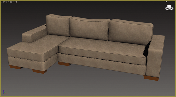
Figure 9-10: The final results of the couch mapping
Save your file and move on to the next exercise. To check your work, open the c9_ex4_mapping_end.max file from the scenes folder of the c9_ArchMaterial project folder.
Exercise 9.5: Adding Materials to the Feet
The couch is not finished just yet; look closely at the couch feet. If you compare the current scene couch to the image of the real couch, you’ll see that the feet should be a dark wood, not the default material on them now. Continue with the file you are working on or open the c9_ex5_feet_start.max file from the scenes folder of the c9_ArchMaterial project folder. Then follow these steps:
- Open the Slate Material Editor if it isn’t already open.
- In the Material/Map Browser, choose Materials, select a Standard material, and drag it into the Active View area.
- Double-click the title bar of the material to add the material parameters to the Material Parameter Editor.
- Change the name to Dark Red Wood.
- Expand the Maps rollout and click the None button across from Diffuse Color. This brings up a separate Material/Map Browser.
- Choose Bitmap, and in the Select Bitmap Image File dialog box, navigate to the
sceneassetsimagesfolder in thec9_ArchMaterialproject folder and select theDarkRedWood.jpgimage file. - Apply the material by clicking and dragging from the node’s output socket to the couch foot, as shown in Figure 9-11.
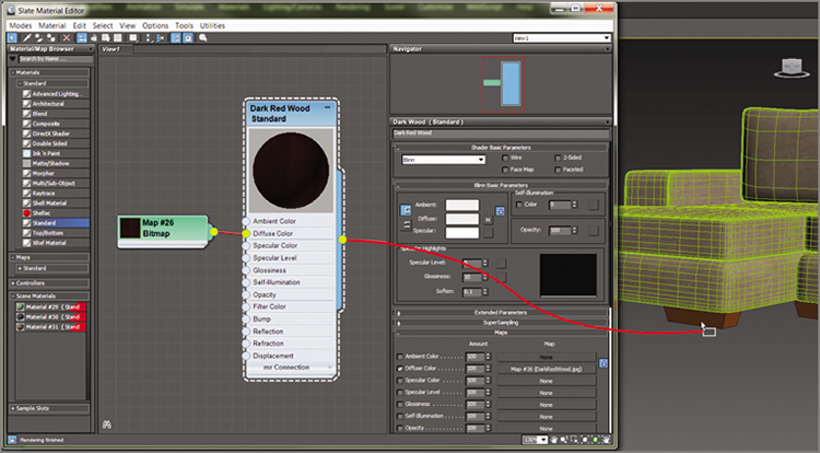
Figure 9-11: Apply the Dark Red Wood material by clicking and dragging from the node’s output socket to the couch foot.
- In the Material Editor, click the Show Shaded Material in Viewport icon. The material shows now, but the image has no detail. This is because it needs to have UVW Mapping applied.
- Select the foot; then, in the Modify panel’s Modifier List, add a UVW Map modifier to the couch foot.
- Change the mapping type to Box, and select Bitmap Fit under Alignment.
- Navigate to the
DarkWood_Grain.jpgimage file. Select the image and then click OK in the dialog box. The material now looks correct on the couch foot. - Apply the Dark Red Wood material to the remaining couch feet.
Save your file and move on to the next exercise. To check your work, open the c9_ex5_feet_end.max file from the scenes folder of the c9_ArchMaterial project folder.
Exercise 9.6: Applying a Bump Map
You are almost finished with the couch. One important feature of the couch is the bumpiness on the surface of the fabric, as shown in Figure 9-12. This bumpiness changes all the specular and reflective properties on a surface.
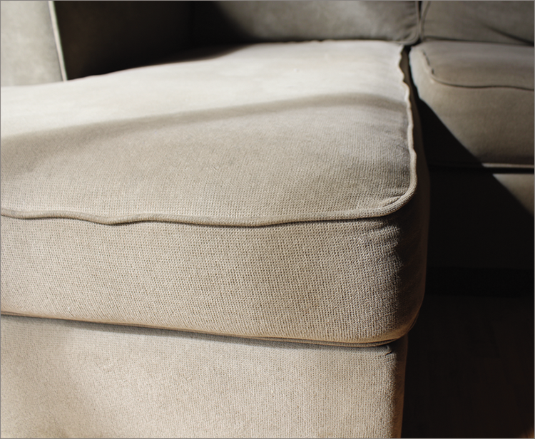
Figure 9-12: The couch fabric showing the subtle surface bumpiness
Bump mapping uses the intensity values (the brightness values) of an image or procedural map to simulate bumpiness on the surface of the model without changing the actual topology of the model itself. You can create some surface texture with a bump map; however, you will not be able to create extreme depth in the model. For that, you may want to model the surface depth manually or use displacement mapping instead. Continue with the file you are working on or open the c9_ex6_bump_start.max file from the scenes folder of the c9_ArchMaterial project folder. To add a bump map to the couch, follow these steps:
- In the Slate Material Editor’s Active View area, locate the Gray/Green Woven Fabric material. Double-click the title bar to load the material into the Material Parameter Editor.
- In the Maps rollout, click the None button next to the Bump map, and in the Material/Map Browser, choose Bitmap.
- Navigate to the
sceneassetsimagesfolder in thec9_ArchMaterialproject folder and select theGrayGreenWovenFabric_bmp.tifimage file. - In the Maps rollout, increase Bump Amount from 30 (the default) to 60.
- Render to see the results. You should now see a texture on the couch that resembles the real bumpiness, as shown in Figure 9-13.
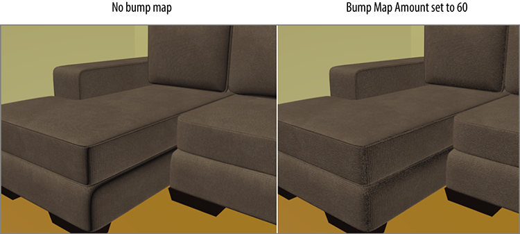
Figure 9-13: The couch fabric without the bump map (left) and with the bump map (right)
Save your file and move on to the next exercise. To check your work, open the c9_ex6_bump_end.max file from the scenes folder of the c9_ArchMaterial project folder.
Build Materials for the Lounge Chair
In this section, you will be adding materials to the lounge chair. Mapping the lounge chair is in some ways very much like mapping the couch. Figure 9-14 shows the lounge chair that was modeled in Chapter 4.
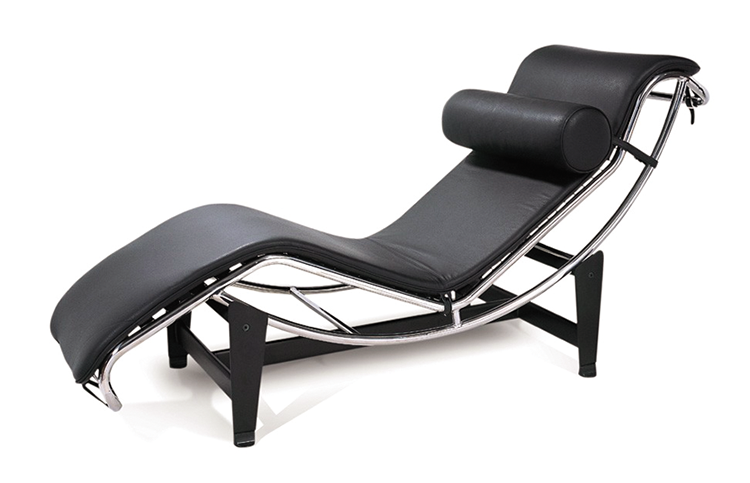
Figure 9-14: The lounge chair
Exercise 9.7: Creating a Leather Material for the Chair Cushion
The file has the lounge chair centered in the viewports, and the chair group is open so you can select the individual pieces. Continue with the file you are working on or open the c9_ex7_chair_start.max file from the scenes folder of the c9_ArchMaterial project folder. You will create the Cushion material using the techniques discussed in the previous section. Then follow these steps:
- In the Slate Material Editor, add a Standard material to the Active View area. Double-click the material title to add it to the Material Parameter Editor.
- In the Maps rollout, click the None button next to the Diffuse map, and in the Material/Map Browser, choose Bitmap.
- Navigate to the
sceneassetsimagesfolder in thec9_ArchMaterialproject folder, select theLeather.tiffile, and rename the material Leather. - Select the lounge chair cushion, and apply the Leather material by clicking the Assign Material To Selection button in the toolbar.
- On the Material Editor toolbar, click the Show Shaded Material in Viewport icon.
- In the Specular Highlights group, change Specular Level to 20 and Glossiness to 9. This will give the leather material a bit of gloss.
- Repeat steps 1 through 6, but add the bitmap to the Bump map channel.
- When the Select Bitmap Image File dialog box opens, choose
Leather_Bmp.tif. - In the Modify panel’s Modifier List, add a UVW Map modifier.
- Change the Mapping type to Box, and in Alignment, select Bitmap Fit. Navigate to the
Leather.tifbitmap, select the image, and then click OK. This will change the size of the UVW Map gizmo. The size of the map is now the proper height-to-width ratio, but it is too large. - In the modifier stack, click the plus sign in the black box and select Gizmo.
- Using the Scale tool, scale the gizmo until the material looks correct, as shown in Figure 9-15.
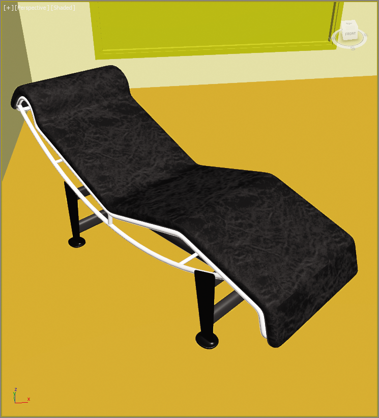
Figure 9-15: The Leather texture is applied to the chair cushion.
Save your file and move on to the next exercise. To check your work, open the c9_ex7_chair_end.max file from the scenes folder of the c9_ArchMaterial project folder.
Exercise 9.8: Creating a Reflective Material
Reflection occurs when light changes direction as a result of “bouncing off” a surface like a mirror. In the following steps, you will create reflections on the lounge chair frame; what you are going to create is a chrome material that has 100 percent reflections. Continue with the file you are working on or open the c9_ex8_reflect_start.max file from the scenes folder of the c9_ArchMaterial project folder.
- In the Material Editor, drag a Standard material from the Material/Map Browser to the Active View area.
- Double-click the title bar of the material to add it to the Material Parameter Editor.
- Rename the material Chrome, and change the diffuse color to black (R: 0, G: 0, B: 0).
- In the Specular Highlights group, change Specular Level to 90 and Glossiness to 80. This will give the chrome material a bit of gloss.
- In the Material/Map Browser rollout, go to the Maps rollout ⇒ Standard, choose Raytrace from the list, and drag the Raytrace map to the Reflection input socket.
- Apply the Chrome material to the lounge chair frame (which is grouped together in this scene). You won’t be able to see the mirror effect of the chrome in the viewport; you will have to render.
- Click the Render Production button. The result of the render is shown in Figure 9-16. In the figure, the chrome doesn’t look smooth. It has a noisy, broken-up look to it. You can correct this by controlling the anti-aliasing.

Figure 9-16: The Chrome material applied to the lounge chair frame
- In the Chrome material, select the SuperSampling rollout. Uncheck Use Global Settings and check Enable Local Supersampler.
- Choose Max 2.5 Star from the drop-down menu, and then render. You should see the difference in the reflections, as shown in Figure 9-17.
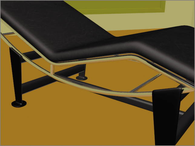
Figure 9-17: Final reflections on the chair frame
The last material is the material that is on the base of the chair. This should be a very simple material to create, a matte black material. Follow the steps learned throughout this chapter. Use a Standard material, and make the diffuse color black. Set Specular Level to 20 and Glossiness to 15. Name the material Base and apply this material to all the objects from the base, as shown in Figure 9-18.
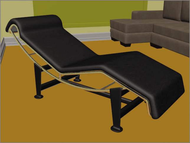
Figure 9-18: The final materials applied to the lounge chair
Save your file and move on to the next exercise. To check your work, open the c9_ex8_reflect_end.max file from the scenes folder of the c9_ArchMaterial project folder.
Build Materials for the Window
The window and doors are special 3D primitive objects. They are a collection of multiple objects attached together: a frame, mullions, and glass. You can edit those objects within the Architecture Engineering and Construction (AEC) object’s parameters. You also have the ability to add materials to the individual pieces within the attached whole.
Exercise 9.9: Creating a Multi/Sub-Object Material
The Multi/Sub-Object material (MSOM), which is in the Compound Materials category, lets you assign different materials at the sub-object level of your geometry. In the case of the AEC window, it is already divided into separate sub-object levels, so you just have to apply the material and identify the different parts. Continue with the file you are working on or open the c9_ex9_MSOM_start.max file from the scenes folder of the c9_ArchMaterial project folder. Then follow these steps:
- In the Slate Material Editor, drag a Multi/Sub-Object material from the Material/Map Browser into the Active View area.
- Double-click the title bar to add the material to the Material Parameter Editor. Click the Set Number button and change Number of Materials to 5, as shown in Figure 9-19. Change the name to Window/Door.
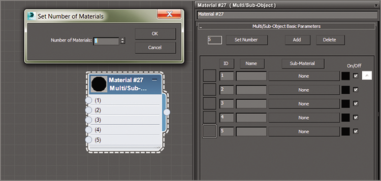
Figure 9-19: Multi/Sub-Object material and parameters
- Drag a Standard material from the Material/Map Browser to the Active View area, and then from the output socket of the Standard material, drag it to the input socket of the MSOM, as shown in Figure 9-20.
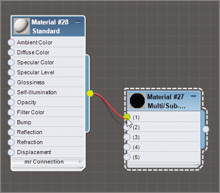
Figure 9-20: Adding a Standard material to the Multi/Sub-Object Material node
- Double-click the new Standard material’s title bar to add it to the Material Parameter Editor. Click the Diffuse color swatch to open the color selector; create a red color, and click OK.
- Repeat the process until you have five Standard materials with five different diffuse colors plugged into the 1 through 5 input sockets of the MSOM. The finished node is shown in Figure 9-21. The Standard material nodes have been minimized for the figure. The numbers in the MSOM parameters are material IDs.
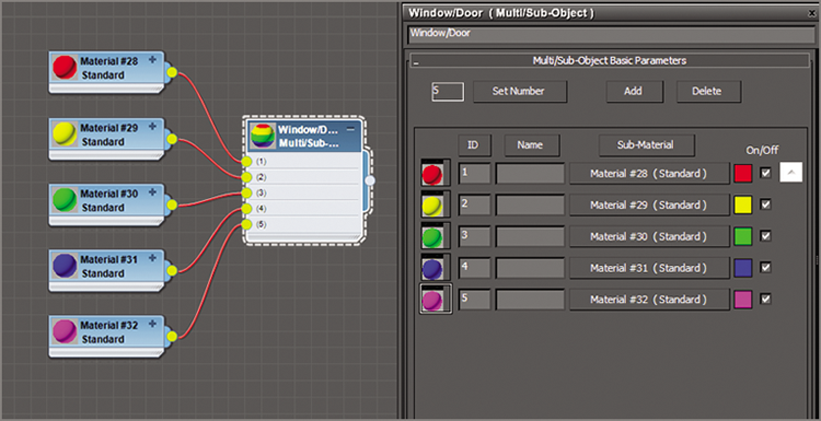
Figure 9-21: Finished MSOM with five Standard materials added
- Apply the MSOM to the window in the living room area, as shown in Figure 9-22. The colors show clearly which section of the window corresponds to which ID number.
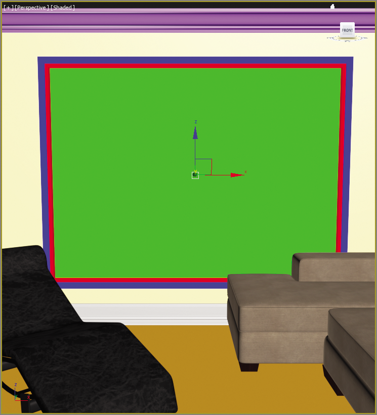
Figure 9-22: The Multi/Sub-Object material applied to the window object shows the different colors applied to the different parts of the window.
- The colored materials that were just created are not needed. Select and delete them.
- Starting with the window glass; select the material bar for ID #3 in the MSOM parameter. This opens the Material/Map Browser, and Select Standard material. Click the material bar for ID #3 in the MSOM parameters. This loads that material’s parameters. Rename the material Window Glass.
- In the Blinn Basic Parameters rollout, change Opacity to 0. If you render, you will see a black hole where the green used to be. That is because you are seeing the default color applied to the background in a render. That means the glass is see-through now.
- In the Maps rollout, click the Reflection Map button.
- From the Material/Map Browser, choose Raytrace, and then change Reflection Amount to 9.
- In the main menu go to the Rendering menu. Choose Environment and then click the color swatch under Background, and change it to a light gray.
- Render the Perspective viewport. Now the reflection looks more appropriate. Eventually, an image of an outdoor scene will be placed behind the glass. For now, let’s continue with the MSOM for the window. Window frames and mullions come in many colors and textures, but for this example you are going to use a shiny white plastic.
- Double-click the MSOM title bar to load the material into the Material Parameter Editor, and then select any of the material IDs (other than #3).
- Repeat the same process as in step 8 to load the material in the MSOM.
- Change the diffuse color to White, and then in the Maps rollout add a Raytrace node to the Reflection map, and change the Amount to 10, as you did in step 11.
- Drag from the output socket of the Shiny White Plastic material to the input of the remaining Multi/Sub-Object material’s IDs, as shown in Figure 9-23.
This places a clone of the Shiny White Plastic material into the three remaining material slots and completes the window material, as shown in a render in Figure 9-24.
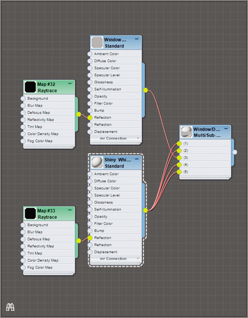
Figure 9-23: Drag from the output socket of the Shiny White Plastic material into the input socket of the remaining ID slots of the Multi/Sub-Object material.
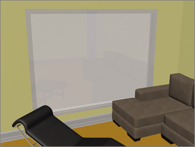
Figure 9-24: The completed window
The same technique used for the window can be used for the doors, but if you want the doors to be just a plain solid color or simple wood, you can apply a Standard material to the entire Door object. We’ll return to this room in Chapter 14 when we look at lighting. Meanwhile, finish assigning materials to the rest of the scene.