
Chapter 15
mental ray
This chapter will show you how to create materials and render your scene using the Autodesk® mental ray® renderer.
In this chapter, you’ll learn to:
- Navigate the mental ray renderer
- Navigate the Final Gather parameters
- Navigate mental ray materials
- Use photometric lights with mental ray
- Use the Daylight System
Navigate the mental ray Renderer
mental ray is a popular general-purpose renderer that has fantastic capabilities. One of mental ray’s strengths is its ability to generate physically accurate lighting simulations based on indirect lighting principles. Indirect lighting occurs when light bounces from one object in a scene onto another object. In addition, incandescence or self-illumination from one object can light other objects in the scene. Direct lighting, such as from an omni light, is not necessarily required. Another thing to consider is that mental ray’s reflections and refractions take on very real qualities when set up and lighted well.
Exercise 15.1: Enabling the mental ray Renderer
Set your project to the c15_mental ray project folder that you downloaded to your hard drive from the companion web page at www.sybex.com/go/3dsmax2015essentials. Open the c15_ex1_assign_start.max file in the scenes folder. You’ll render a movie to see the animation. To enable mental ray, follow these steps:
- Choose Rendering ⇒ Render ⇒ Render Setup or select the icon in the main toolbar (
 ) or use the shortcut, F10, to open the Render Setup dialog box.
 - On the Common tab, scroll down to the Assign Renderer rollout. Click the Assign Renderer rollout bar to expand it. Select the ellipsis button for the Production entry, as shown in Figure 15-1. This opens the Choose Renderer dialog box.
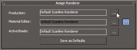
Figure 15-1: The Assign Renderer rollout
- In the Choose Renderer dialog box, highlight NVIDIA mental ray, and then click OK.
Save the file. To check your work you can open the c15_ex1_assign_end.max file in the c15_mental ray project folder.
mental ray Sampling Quality
Once the mental ray renderer is enabled, click the Renderer tab in the Render Setup dialog box. The following is a brief explanation of the render settings most useful for you in your work.
Under the Sampling Quality rollout, shown in Figure 15-2, are the settings that let you control the overall image quality of your renders.
In the Sampling Mode drop-down list, there are three options to choose from. Unified/Raytraced (Recommended) is the default. This mode raytraces the scene using the same sampling method for both anti-aliasing and calculating motion blur. This results in far quicker rendering than the Classic/Raytraced method.
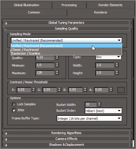
Figure 15-2: The Renderer tab shows mental ray’s common settings.
Quality essentially sets the “noise level” at which the renderer stops sampling. Higher quality implies less noise. The Quality parameter sets the quality of rendering. The lower the values, the faster the render, but the render is much grainier, as shown in Figure 15-3. The higher the value, the smoother the images, as shown in Figure 15-4, but they take longer to render.

Figure 15-3: A Quality setting of 0.01 renders a noisy image.
Figure 15-4: A Quality setting of 20.0 renders a smooth image.
Navigate the Final Gather Parameters
A popular feature in mental ray is indirect illumination—the simulation of bounced light (explained in the next section). Click the Global Illumination tab at the top of the Render Setup dialog box. There are four rollouts, the second of which we will explore further:
- Skylights & Environment Lighting (IBL)
- Final Gathering (FG)
- Caustics & Photon Mapping (GI)
- Reuse (FG And GI Disk Caching)
Final Gather is a method of mental ray rendering for estimating global illumination (GI). In short, global illumination is a way of calculating indirect lighting. This way, objects do not need to be in the direct path of a light (such as a spotlight) to be lit in the scene. mental ray accomplishes this by casting points throughout a scene. These light points are allowed to bounce from object to object, contributing light as they go, effectively simulating how real light photons work in the physical world.
Figure 15-5 shows the Final Gathering (FG) rollout. Some of the Final Gather options, including how to deal with quality and noise, are explained next.
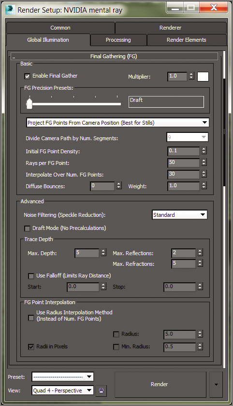
Figure 15-5: The Final Gathering (FG) rollout in the Global Illumination tab of the Render Setup dialog box
Basic Group
These are the most important parameters in the Basic group of the Final Gathering (FG) rollout; they set the accuracy and precision of the light bounces, thereby controlling noise:
- FG Precision Presets Slider Sets the accuracy level of the Final Gather simulation by adjusting settings for the renderer such as Initial FG Point Density, Rays Per FG Point, and Interpolate Over Num. FG Points. Use this slider first in setting how well your render’s lighting looks. In the left image in Figure 15-6, three spheres are rendered with the Draft setting for Final Gather, while the right image is set to High. Notice that the right image is a cleaner render, and it also shows more of the background and the spheres than does the Draft quality in the left image. This slider will adjust the settings for several of the values covered in the following list.
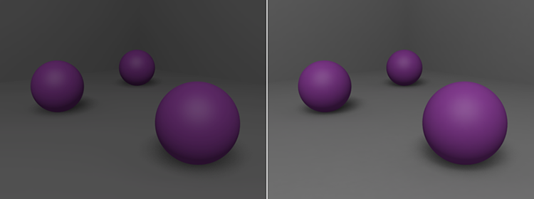
Figure 15-6: The Draft setting produces a test render of the spheres (left). The High setting produces a better-quality render of the spheres (right).
- Initial FG Point Density This multiplier controls the density for the Final Gather points. This is one of the settings adjusted by the FG Precision Presets slider, but it can also be set manually. This value sets the quantity and density of FG points that are cast into the scene. The higher the density of these points, the more accurate the bounced light appears, at a cost of render time.
- Rays Per FG Point This value is controlled by the FG Precision Presets slider but can also be manually set. The higher the number of rays used to compute the indirect illumination in a scene, the less noise and the more accuracy you gain, but at the cost of longer render times.
- Interpolate Over Num. FG Points Interpolation is controlled by the FG Precision Presets slider as well as manual input. This value is useful for getting rid of noise in your renders for smoother results. Increasing the interpolation will increase render times but not as much as increasing the Initial FG Point Density or Rays Per FG Point values.
- Diffuse Bounces The number of bounces governs how many times a ray of light can bounce and affect objects in a scene before stopping calculation. If you set the number of bounces higher, the light simulation will be more accurate, but the render times will be costly. A Diffuse Bounces setting of 1 or 5 is adequate for many applications. Figure 15-7 shows the same render of the spheres as Figure 15-6, but with a Diffuse Bounces value of 5. This render is brighter and also shows color bleed from the purple spheres onto the gray floor.
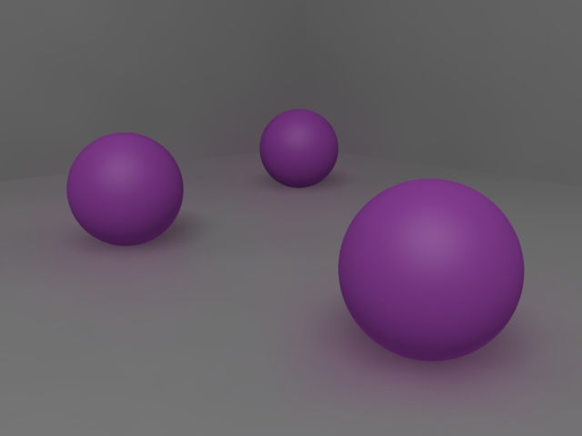
Figure 15-7: More diffuse bounces mean more bounced light.
Advanced Group
The Advanced group of settings gives you access to additional ways of controlling the quality of your Final Gather renders. Some are described next, in brief. You should experiment with different settings as you gain more experience with Final Gather to see what settings work best for your scenes.
- Noise Filtering (Speckle Reduction) This value essentially averages the brightness of the light rays in the scene to give you smoother Final Gather results. The higher the filtering, the darker your Final Gather simulation, and the longer your render times will be. However, the noise in your lighting will diminish.
- Draft Mode (No Precalculations) This setting allows you to turn off a good number of calculations that mental ray completes prior to rendering the scene. Enabling this setting results in a faster render for preview and draft purposes.
- Max. Reflections This value controls how many times a light ray can be reflected in the scene. A value of 0 turns off reflections entirely. The higher this value, the more times you can see a reflection. For example, a value of 2 allows you to see a reflection of a reflection.
- Max. Refractions Similar to Max. Reflections, this value sets the number of times a light ray can be refracted through a surface. A value of 0 turns off all refraction.
The mental ray Rendered Frame Window
When you render a scene using the Autodesk® 3ds Max® program, the Rendered Frame window opens, displaying the image you just rendered. When you render with mental ray, an additional control panel is displayed under the Rendered Frame window, as shown in Figure 15-8.
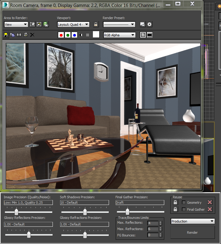
Figure 15-8: The Rendered Frame window now shows several mental ray controls.
This control panel gives you access to many of the most useful settings in the Render Settings dialog box so you can adjust render settings easily and quickly.
Navigate mental ray Materials
For the most part, mental ray treats regular 3ds Max maps and materials the same way the Default Scanline renderer does. However, a set of mental ray–specific materials exists to take further advantage of mental ray’s power. The mental ray Arch & Design material works great for most hard surfaces, such as metal, wood, glass, and ceramic. It is especially useful for surfaces that are glossy and reflective, such as metal and ceramic. To showcase these materials, let’s retexture a few of the features from the room from Chapter 9, “Introduction to Materials.”
Exercise 15.2: Setting Up the Material Editor
Set your project to the c15_mental ray project folder that you downloaded from the web page at www.sybex.com/go/3dsmax2015essentials. Open the c15_ex2_materials_start.max file from the scenes folder from the c15_mental ray project folder. This file has NVIDIA mental ray already assigned as the renderer. The scene includes the room and the textured furniture. There are no lights in the scene, but because NVIDIA mental ray is the assigned renderer, it utilizes the default lights to generate a lighted scene, as shown rendered in Figure 15-9. mental ray renders the materials from the previous chapter; some look the same, but others don’t look so good.
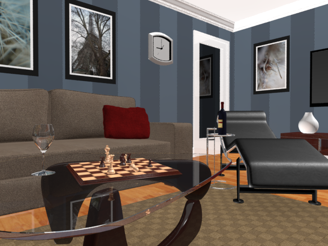
Figure 15-9: The file rendered with mental ray
- Open the Slate Material Editor, and then look at the top of the active view. You will see a tab called View 1; it holds all the materials that were created for the scene.
- To keep the new materials that will be created separate and organized, create another tab for the mental ray materials. To create a new tab, right-click in the blank area next to the tab, as shown in Figure 15-10, create a new view, and name it mental ray.
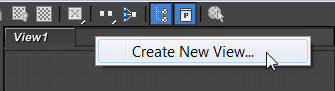
Figure 15-10: Create a new view.
Save the file. To check your work you can open the c15_ex2_materials_end.max file in the c15_mental ray project folder.
Exercise 15.3: Using Arch & Design Material Templates
In the Material/Map Browser, you will see an additional rollout, mental ray. This gives a whole new set of materials, including the Arch & Design materials. Arch & Design materials have a special feature: templates. Templates provide access to already created materials and parameters for different types of materials, such as wood, glass, and metal. These templates can also be used as a starting point for material creation. Open the c15_ex3_materials_start.max file from the scenes folder from the c15_mental ray project folder. You will use one to create the material for the tabletop and wineglass in the following steps:
- Drag an Arch & Design material to the new active view from the mental ray material section of the Material/Map Browser.
- Double-click the title of the node; this will display the Arch & Design material in the Material Parameter Editor.
- Name the material Thick Glass.
- From the Material Parameter Editor, in the Select a Template drop-down menu, choose Glass (Solid Geometry), as shown in Figure 15-11.
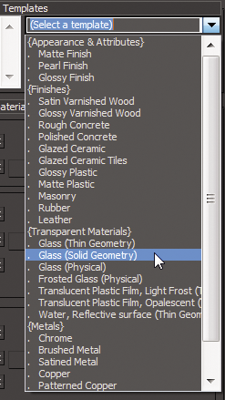
Figure 15-11: Arch & Design Glass (Solid Geometry) from the template drop-down menu
- Drag a wire from the Thick Glass material’s output socket to the wineglass object.
- Render the Room Camera viewport to see the new material on the coffee table top. There is some blue in the glass; this is from the Refraction color.
- Select the Refraction Color swatch and change the color to achieve a colored tint to the glass. Change the color to white to get a clear glass.
- Render the scene, as shown in Figure 15-12.
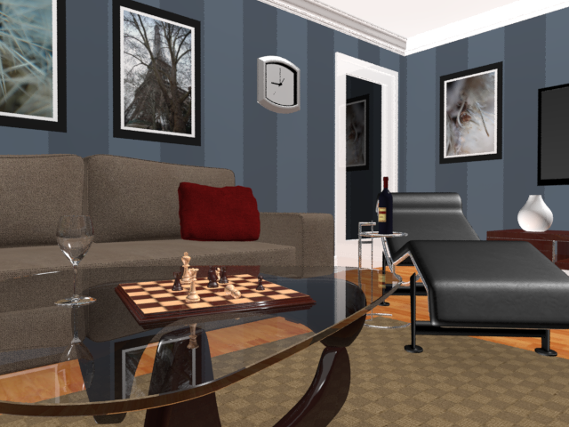
Figure 15-12: Refraction color changed to white to achieve clear glass
- Press the C key on the keyboard. This will bring up the Select Camera dialog box, which includes a list of cameras in the scene.
- Select the Lounge Chair/Table Camera. Click OK to close the dialog box.
- In the Material Parameter Editor, create a new Arch & Design material and choose Chrome from the template list. Name it Chrome.
- Select the pieces of the side table and lounge chair that need to be chrome, which are all the pieces of the table except the glass, as well as the frame of the lounge chair. When you apply the material, you will get an error message, as shown in Figure 15-13, telling you that a material with the same name already exists. This material is a Standard material that was previously applied.
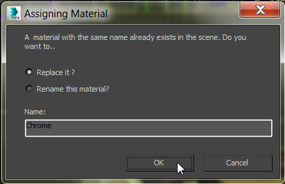
Figure 15-13: The message warns you about assigning a material with a duplicate name to an object.
- Select the Replace It? radio button.
- Render to see the new Chrome material applied to the side table and lounge chair frame, as shown in Figure 15-14.
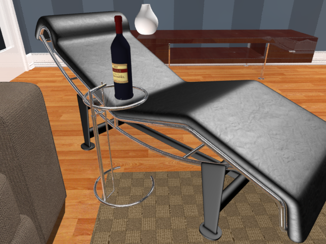
Figure 15-14: The new Chrome material applied to the chair frame and side table
Save the file. To check your work, open the c15_ex3_materials_end.max file in the c15_mental ray project folder.
Exercise 15.4: Creating Arch & Design Materials
Using the Arch & Design material, you will create a new material for the floor. There is a template called Glossy Varnished Wood, but you are going to create the floor material from scratch. Open the c15_ex4_materials_start.max file from the scenes folder of the c15_mental ray project folder.
- Switch from the Lounge Chair/Table Camera to the Floor Camera using C to bring up the Select Camera dialog.
- Open the Material Parameter Editor if it isn’t already open, and drag an Arch & Design material to the new active area from the mental ray rollout of the Material/Map Browser.
- Double-click the title of the node to display the Arch & Design material parameters in the Material Parameter Editor. Name the material Hardwood Floors.
- Drag a bitmap from the Maps rollout to the Diffuse Color Map input socket of the Arch & Design material. This will bring up the Select Bitmap Image File window.
- Choose the
Hardwood_honey.tiffile. Leave all the other parameters at the default. - Apply the material to the floor. You will get an error window telling you that there is a material with the same name already applied. Select Replace It? from the dialog. If the Hardwood Floors material doesn’t show up in the viewport, click the Show Shaded Material In Viewport button (
 ). Render the Floor Camera viewport. The results are shown in Figure 15-15.
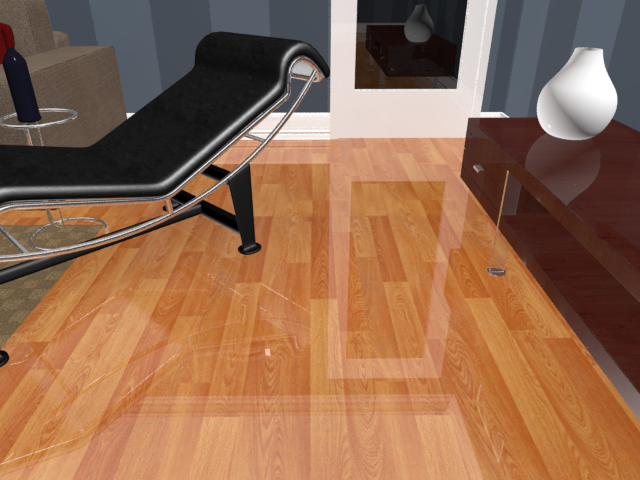
Figure 15-15: Floor with the Arch & Design material applied
- In the Material Editor, in the Reflection group, leave Reflectivity at 0.6 and change Glossiness to 0.6.
- Render the camera to see the results, as shown in Figure 15-16.
Figure 15-16: The Hardwood Floors material showing the change in the reflections
By default, Arch & Design materials have reflection enabled. The area below the Diffuse group in the Material Parameter Editor of the Slate Material Editor is the Reflection group of parameters. Reflections for this material are calculated using the Reflectivity and Glossiness values. The higher the Reflectivity value, the clearer the reflections. The Glossiness value controls the blurriness of the reflections from sharp (a value of 1) to completely blurred (a value of 0). When you blur your reflections, the blurrier they are, the noisier they will be in the render. You can use the Glossy Samples value to increase the quality of the blurred reflections once you set Glossiness to anything less than 1. The floors should not be so reflective.
You can use the same techniques for creating Arch & Design materials for the other objects in the scene, like the base of the coffee table and the couch. Save the file. To check your work open the c15_ex4_materials_end.max file in the c15_mental ray project folder.
Exercise 15.5: Using the Multi/Sub-Object Material and Arch & Design
You can use the same technique for the window that you used in Chapter 9, but the difference is that you will use the Arch & Design material instead of the Multi/Sub-Object material. The window is divided into two materials: shiny white for the frame and a shiny transparent material for the glass. Another way to apply a Multi/Sub-Object material is to apply the material to the selected sub-objects. Open the c15_ex5_materials_start.max file from the scenes folder of the c15_mental ray project folder.
- Switch from the Floor Camera to the Window Camera by pressing C to bring up the Select Camera dialog box.
- Select the window and go to the Graphite Modeling Tools tab ⇒ Polygon Modeling ⇒ Convert to Poly.
- Enter Polygon mode (
 ), and select all the polygons for the window frame. The simplest way to do this is to select the Window object, hold down Alt, and click just the window glass; this will deselect the glass. There are front and back Window objects.
 - In the Slate Material Editor, you’ll create a shiny white material: Drag an Arch & Design material to the mental ray active area, and change the Diffuse color to R = 1.0, G = 1.0, B = 1.0 and rename it White Window Frame. Based on what you know about reflections from the previous steps, the default reflections are too high, especially for the frame on the window.
- In the Reflection group, change Reflectivity to 0.4 and Glossiness to 0.4.
- Apply the material to the selected sub-objects using the Assign Material To Selection button (
 ).
). - Now go to the main toolbar ⇒ Edit menu and choose Select ⇒ Select Invert; this will deselect the window frame and select the window glass.
- Back in the Material Parameter Editor, drag an Arch & Design material to the mental ray active area.
- Double-click the title bar of the new Arch & Design material to load it into the Material Parameter Editor.
- In the Select A Template drop-down menu, choose Glass (Thin Geometry), and select the Show Background In Preview icon (
 ). This will place a checker pattern behind the sample sphere to make the transparency easier to edit. Rename the material Window Glass.
You can see that the window and frame look very similar to the Standard materials, but the coffee table and floor look significantly better than with their previous Standard material. When you’re using mental ray, Arch & Design materials are superior. Sometimes the look of a particular object can change depending on the camera angle and lighting. Keep an eye on the window to see if the look maintains the realism you are after.
The Arch & Design material type is an elaborate construct of mental ray shaders, and with proper lighting it can make any render look special. If you open the c15_ex5_materials_end.max file, you will see several examples of materials beyond what you created in the previous exercise, as shown in Figure 15-17.
Save the file. To check your work, open the c15_ex5_materials_end.max file in the c15_mental ray project folder.
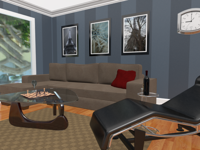
Figure 15-17: The final render of the mental ray materials
Use Photometric Lights with mental ray
Photometric lights simulate real lighting by using physically based energy values and color temperatures. Many of the parameters for photometric lights are the same as or very similar to the standard lights you looked at in Chapter 13, “Introduction to Lighting: Interior Lighting.”
Exercise 15.6: Using Photometric Lights in mental ray Renderings
Here you see the parameters that are specific to photometric lights. To learn about photometric lights, follow these steps:
- Open the
c15_ex6_ light_start.maxfile from thescenesfolder of thec15_mental rayproject folder from the book’s web page. - To create a light, one method is to go to the main menu bar and choose Create ⇒ Lights ⇒ Photometric Lights ⇒ Target Light to create a photometric target light.
- When you click on the Target Light, you will get a pop-up, Photometric Light Creation, recommending that you use the mr Photographic Exposure Control, as shown in Figure 15-18. Click Yes.
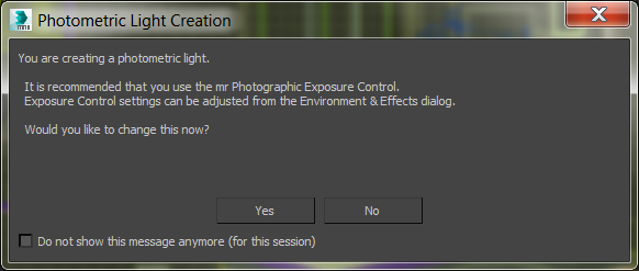
Figure 15-18: Select Yes in the Photometric Light Creation dialog box.
- In the Left viewport, click to create the light, and then drag from the ceiling down to the floor. Make sure you stay within the room.
- You will need to move the light into the room. Both the light source and target need to be selected. The easiest way to select both the light and the target is to select the blue string that runs between the two objects.
- Switch to the Top viewport, and with the Move tool move the light and its target so they are above the coffee table.
- Change the viewport rendering type to Realistic in the Room Window Camera viewport.
- Select the light source and go to the Modify panel.
- The first rollout under the modifier stack is Templates. Then in the Select A Template drop-down menu, select Recessed 75W Wallwash (Web). When you add a template to a photometric light a new rollout appears. Figure 15-19 shows a photometric light rollout with a “web” distribution essentially defining the light’s behavior and the light it casts.
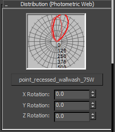
Figure 15-19: The Distribution (Photometric Web) rollout
- You need to take care of some basic stuff now, so with the light still selected, open the General Parameters rollout and check the Targeted box. Checking this box turns the target back on for the light.
- Click the Shadows On box to turn it on. From the drop-down menu, choose Ray Traced Shadows.
- Choose Rendering ⇒ Exposure Control, and click the Render Preview button in the Exposure Control rollout, as shown in Figure 15-20.
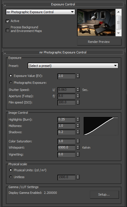
Figure 15-20: Exposure Control and mr Photographic Exposure Control rollouts in the Environment and Effects dialog box
- Under the mr Photographic Exposure Control rollout, select Exposure Value (EV) if it isn’t already selected.
- Set some different values for the EV and see what happens in the Render Preview window. The higher the EV number, the darker the scene will be; when you change the exposure value, the Render Preview window updates. Set the EV to 3 and render the Room Window Camera. Then render the Room Window Camera viewport, as shown in Figure 15-21.
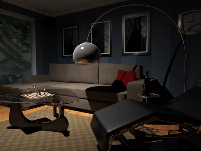
Figure 15-21: The room so far
- You can continue to work with the EV to experiment with the luminance level. When you’ve finished experimenting, be sure to set the EV to 3 and close the Environment and Effects dialog box.
- With the 75W light still selected, go to the Modify panel, and in the Color group in the Intensity/Color/Attenuation rollout, click the radio button next to Kelvin and change the value to 5600. This will give the light a bit more warmth by adding more yellow/red.
- In the Dimming group, uncheck the box next to the 100% spinner under Resulting Intensity to enable the Intensity parameter.
- In the Intensity group, select cd, as shown in Figure 15-22, and set the cd amount to 200. This will brighten things up a bit.
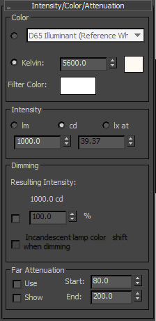
Figure 15-22: Intensity/Color/Attenuation rollout showing the changed parameters
- Render the scene. The result is shown in Figure 15-23. The scene still looks a bit dark and the shadows are very dark; they look like black holes. You will use Final Gather to brighten up the overall render.
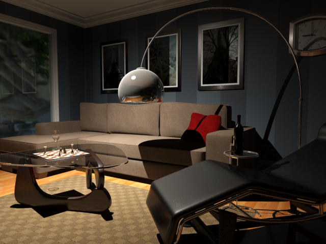
Figure 15-23: The room render with color and intensity changes
- In the mini panel below the Rendered Frame window, shown in Figure 15-24, change FG Bounces to 7.
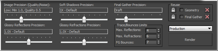
Figure 15-24: This mini panel gives you access to Final Gather controls to adjust your render easily.
- Render the scene and compare the resulting render shown in Figure 15-23 to Figure 15-25. Figure 15-25 shows the final render.
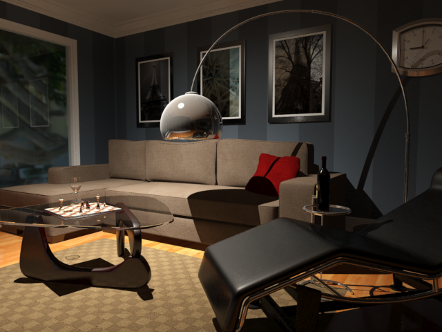
Figure 15-25: The final mental ray render of the room’s interior lighting
Save the file. To check your work, open the c15_ex6_materials_end.max file in the c15_mental ray project folder.
Photometric Light Parameters
Now let’s look in the command panel at the photometric light’s Intensity/Color/Attenuation rollout for the 75W light.
The Color group of parameters controls the color temperature of the light, which you can set either with a color value or in Kelvin units, just as with real-world photographic lights. In the drop-down menu, there are different color/temp settings. The default is D65 Illuminant (Reference White).
The Intensity group of parameters controls the strength or brightness of the lights measured in lm, cd, or lx.
- lm (lumen) This value is the overall output power of the light. A 100-watt general purpose light bulb measures about 1750 lm.
- cd (candela) This value shows the maximum luminous intensity of the light. A 100-watt general-purpose light bulb measures about 139 cd.
- lx at (lux) This value shows the amount of luminance created by the light shining on a surface at a certain distance.
The parameters in the Dimming section are also used to control the intensity of the light. When the Resulting Intensity box is checked, the value specifies a multiplier that dims the existing intensity of the light and takes over control of the intensity.
Use the Daylight System
The Daylight System simulates sunlight by following the geographically correct angle and movement of the sun over the earth. You can choose location, date, time, and compass orientation to set the orientation of the sun and its lighting conditions. You can also animate the date and time to achieve very cool time-lapse looks and shadow studies.
Exercise 15.7: Using the Daylight System in mental ray Renderings
In essence, this type of light works really well with mental ray and Final Gather. In this exercise, you will use it in the most basic way, using all of its defaults.
- Open the
c15_ex7_daylight_start.maxfile from thescenesfolder of thec15_mental rayproject folder. - Choose Create ⇒ Lights ⇒ Daylight System.
- A Daylight System Creation warning will appear, as shown in Figure 15-26, asking if you want to change the exposure controls to suit the Daylight System. Click Yes.
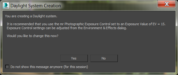
Figure 15-26: The Daylight System Creation warning
- In a Top viewport, click and drag at the center of the scene. This will create a compass that is attached to the Daylight System. Make it the size of the room.
- When you release the mouse button, move the mouse so the light is placed outside the walls of the room. The Daylight System is supposed to simulate the sun and sky, so it needs to be outside the room.
- With the light still selected, open the Modify panel, and in the Daylight Parameters rollout, change the drop-down menus under both Sunlight and Skylight to mr Sun and mr Sky, respectively.
- When you change the Skylight parameter, a mental ray Sky warning will appear, asking if you want to place a mr Physical Sky environment map in your scene. Click Yes.
- Also in the Daylight Parameters rollout, under the Position rollout, select Manual. This will allow you to use the Move tool to move the light to where you want it. The default position represents noon.
- Move the light so it is going through the window, as shown in Figure 15-27.
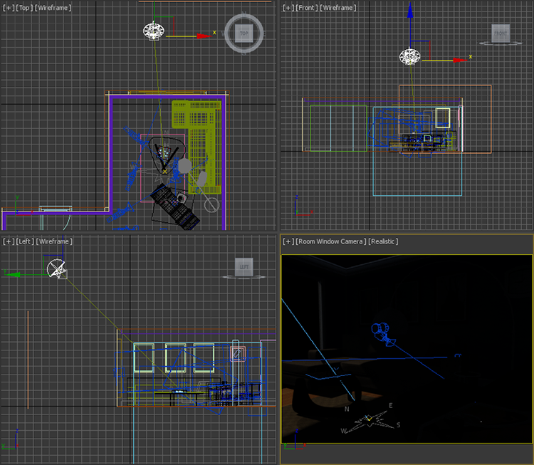
Figure 15-27: Move the Daylight System light so it will shine through the window.
- Select the Room Window Camera viewport and render. As you can see, it is too dark. You are trying to simulate a sunny day, and beyond the direct light coming through the window, it’s pretty dark, as shown in Figure 15-28.
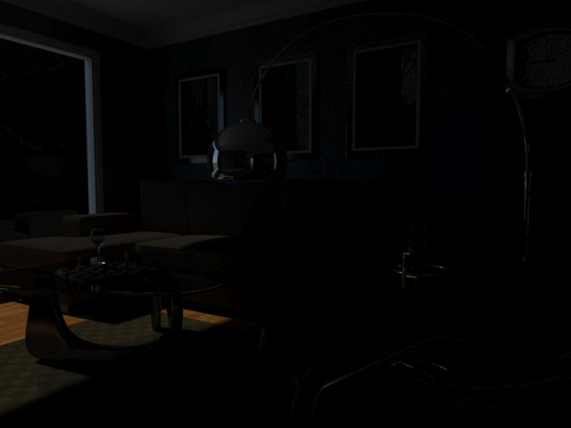
Figure 15-28: This scene is too dark.
- Choose Create ⇒ Lights ⇒ Photometric Lights ⇒ mr Sky Portal.
- In the Front viewport, drag the mr Sky Portal so it fits the window size in the wall.
- Then in the Top viewport, move the mr Sky Portal back so it is aligned with the opening of the window outside the room. Make sure the arrow is pointing into the room, as shown in Figure 15-29. Figure 15-29 is shown with just the walls, window, Daylight System, and mr Sky Portal.
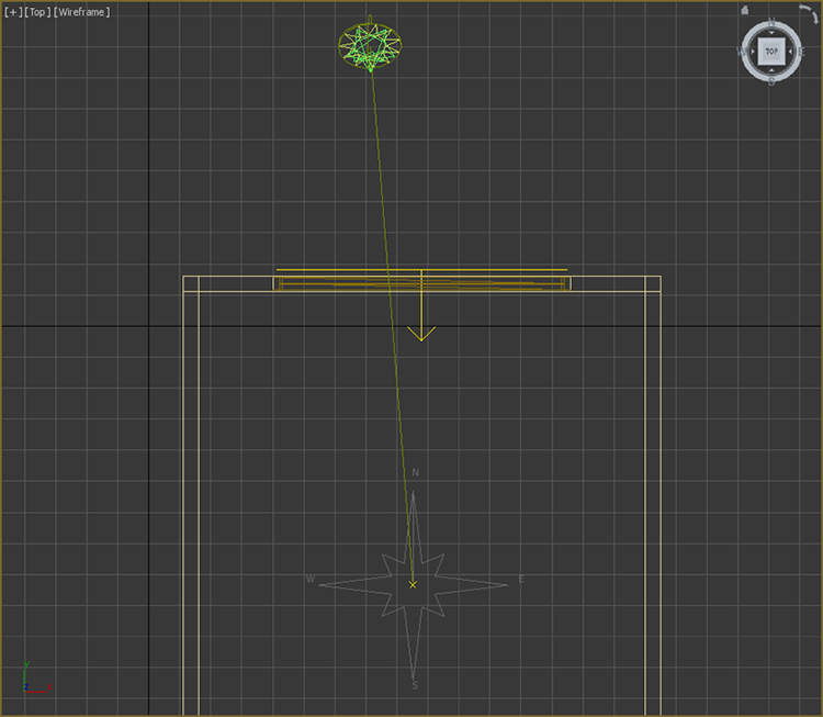
Figure 15-29: Move the mr Sky Portal to the window in the wall in the Top viewport.
- Render the Room Window Camera viewport again. That helps, but it is not enough; it is still too dark, so it’s time to play with exposure controls.
- Choose Rendering ⇒ Exposure Control. Click Render Preview.
- In the mr Photographic Exposure Control rollout, change Exposure Value (EV) from 15 (the default) to 9. You should see the render preview change to show the update.
- Render the Room Window Camera viewport again to see the difference. It looks good but is still a bit dark, so it’s time to add Final Gather bounces.
- In the Rendered Frame window, change FG Bounces to 5. Render the viewport again.
That’s it! If you want to play around some more, try moving the light for a more dramatic shadow on the floor. Moving the light can have a dramatic effect on the luminance levels, so be prepared to edit FG Bounces and Exposure Controls. The last render is shown in Figure 15-30. Don’t be surprised if it takes a while to render.
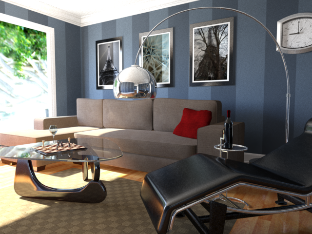
Figure 15-30: The final render
Open the c15_ex7_daylight_end.max file to compare it to your file.