
3
Pile Foundations, Substructures and Basements
It is common for framed buildings to bear onto piled foundations. Steel and concrete columns, known as pile foundations, can be inserted (driven) or bored into the ground, transferring the building loads to loadbearing strata. The loadbearing strata may be a considerable depth below the surface of the ground. When building on previously developed sites, it is common practice to identify and remove existing foundations or to avoid them when placing the piles. Alternatively, some or all of the existing foundations may be reused to avoid unnecessary ground disturbance and help to reduce the environmental impact (and cost) of the new development. For temporary structures it is possible to use timber piles that can be left in the ground to decay naturally or steel screw piles that can be removed (unscrewed) when the building is taken down. In this chapter, the emphasis is on piled foundations, substructures and basements. The main functional requirements of foundations are described in Barry’s Introduction to the Construction of Buildings.
3.1 Pile foundations
The word ‘pile’ is used to describe columns, usually of reinforced concrete, driven into or cast in the ground in order to carry foundation loads to deep underlying firm stratum, or to transmit loads to the subsoil by the friction of their surfaces in contact with the subsoil (see Figure 3.1). The main function of a pile is to transmit loads to lower levels of ground by a combination of friction along their sides and end bearing at the pile point or base. Piles that transfer loads mainly by friction to clays and silts are termed friction piles, and those that mainly transfer loads by end bearing to compact gravel, hard clay or rock are termed end‐bearing piles. Four or more piles may be used to support columns of framed structures. The columns are connected to a reinforced concrete pile cap connected to the pile, as illustrated in Figure 3.2. Piles may be classified by their effect on the subsoil as displacement piles or non‐displacement piles. Displacement piles are driven, forced or cut (by an auger) into the ground to displace subsoil. The strata are penetrated. No soil is removed during the operation. Solid concrete or steel piles and piles formed inside tubes, which are driven into the ground and which are closed at their lower end by a shoe or plug, which may either be left in place or extruded to form an enlarged toe, are all forms of displacement pile. Non‐displacement piles are formed by boring or other methods of excavation that do not substantially displace subsoil. Sometimes the borehole is lined with a casing or tube that is either left in place or extracted as the hole is filled.

Figure 3.1 End‐bearing and friction piles.
Figure 3.2 Pile foundation and pile caps.
Driven piles are those formed by driving a precast pile and those made by casting concrete in a hole formed by driving. Bored piles are those formed by casting concrete in a hole previously bored or drilled in the subsoil.
Driven piles – Concrete
Square, polygonal or round section reinforced concrete piles are cast in moulds in the manufacturer’s yard and are cured to develop maximum strength. The placing of the reinforcement and the mixing, placing, compaction and curing of the concrete can be accurately controlled to produce piles of uniform strength and cross‐section. The precast piles are often square section with chamfered edges, as illustrated in Figure 3.3 and Photograph 3.1. The head of the pile is reinforced with helical binding wire; this helps prevent damage that would otherwise be caused by driving the pile into the ground. Once the pile is in place, the concrete at the top of the pile is removed to expose the main reinforcement. The helical reinforcement can be removed once the main reinforcement bars, which will be tied into the pile cap, are exposed.

Figure 3.3 Head of precast concrete pile.

Photograph 3.1 Driven precast concrete piles.
(Source: http://www.roger‐bullivant.co.uk).
To assist driving, the foot of the pile may be finished with a cast iron shoe, as illustrated in Figure 3.4. Figure 3.5 is an illustration of a typical pile. The piles are lifted into position and driven into the ground by means of a mechanically operated drop hammer attached to a mobile piling rig. To increase the length of the pile to the required depth, additional segments are added (Figure 3.6). The pile is driven in until a predetermined ‘set’ is reached. The word ‘set’ is used to describe the distance that a pile is driven into the ground by the force of the hammer falling a measurable distance. From the weight of the hammer and the distance it falls, the resistance of the ground can be calculated and the bearing capacity of the pile calculated. To connect the top of the precast pile to the reinforced concrete foundation, the top 300 mm of the length of the pile is broken to expose reinforcement to which the reinforcement of the foundation is connected.

Figure 3.4 Shoe of precast concrete pile.

Figure 3.5 Precast reinforced concrete pile.
Figure 3.6 Precast concrete pile segment.
(Source: adapted from http://www.roger‐bullivant.co.uk).
Precast‐driven piles are not generally used on sites in built‐up areas. Difficulties may be experienced when attempting to move large precast piles through narrow streets, although using smaller sections may overcome this problem. The logistics of moving precast and prefabricated objects should always be considered when selecting construction methods. The noise, vibration and general disturbance caused by driving (hammering) piles into the ground can be a nuisance. Where vibration is excessive, or buildings and structures are sensitive to vibration, damage may be caused to adjacent buildings, structures and services. Driven piles are used as end‐bearing piles in weak subsoils, where they are driven into a firm underlying stratum. Driven piles give little strength in bearing due to friction of their sides in contact with the soil, particularly when the surrounding the soil is clay. This is due to the fact that the operation of driving moulds the clay around the pile and so reduces frictional resistance between the pile and the surrounding clay. In coarse‐grained cohesionless soils, where the piles do not reach a firm stratum, driven piles act as friction‐bearing piles due to the action of pile driving, which compacts the coarse particles around the sides of the pile and so increases frictional resistance and in compacting the soil increases its strength. This type of piled foundation is sometimes described as a floating foundation, as is a cast‐in‐place piled foundation, as bearing is mainly by friction and in effect the piles are floating in the subsoil rather than bearing on firm soil.
Driven tubular steel piles
Tubular steel piles are similar in principle to precast concrete piles. Typically the piles are 6 m long, although shorter 3 m segmental piles can be used in areas where access and headroom are restricted (Figure 3.7 and Photograph 3.2). The piles are particularly suitable for driving in difficult or uncertain ground conditions up to 50 m deep. Hard driving conditions caused by fill, obstructions and boulders can also be dealt with. The piles are capable of taking large axial loads. Tubular steel piles can also accommodate horizontal loads resulting from bending moments and horizontal reaction, and can resist vertical tension loads that are a result of uplift and heave reactions.

Figure 3.7 Steel tubular piles.
(Source: adapted from http://www.roger‐bullivant.co.uk).
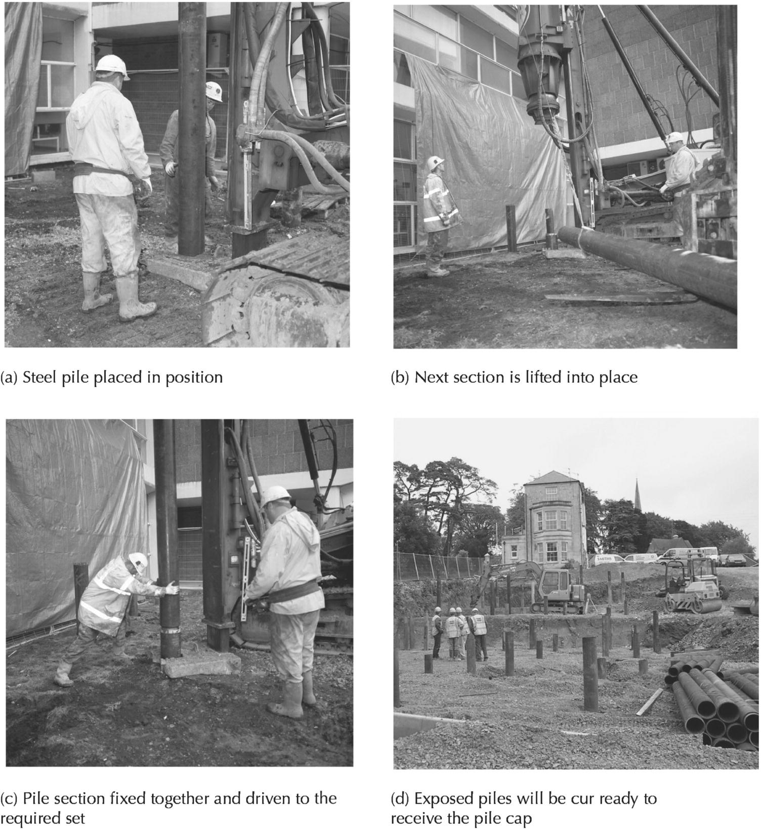
Photograph 3.2 Driven segmental steel piles.
(Source: http://www.roger‐bullivant.co.uk).
Normally the piles are driven with an open end so that soil fills and plugs the void; in exceptional circumstances, the end of the pile can be closed by welding and end plate. The void at the top of the pile is filled with concrete. Reinforcement can be positioned in the pile, allowing it to be tied into the pile caps reinforcement cage. The piles are top driven using rigs with hydraulic hammers. The site should be firm, dry and level ready to receive the piling rigs, which can weigh up to 35 tonnes.
Driven cast‐in‐place piles
Driven cast‐in‐place piles are of two types: the first has a permanent steel or concrete casing and the second uses a temporary casing. The purpose of driving and maintaining a permanent casing is to consolidate the subsoil around the pile casing by the action of driving.
The lining is left in place to protect the concrete cast inside the lining against weak strata of subsoil that might otherwise fall into the pile excavation. Permanent casings also protect the green concrete (concrete which has not set) of the pile against static or running water that may erode the concrete. The lining also protects the concrete against contamination. Figure 3.8 shows a driven cast‐in‐place pile with a permanent reinforced concrete casing. Precast reinforced concrete shells are threaded on a steel mandrel. Metal bands and bitumen seal the joints between shells. The mandrel and shells are lifted on to the piling rig and then driven into the ground. At the required depth, the mandrel is removed, a reinforcing cage is lowered into the shells and the pile completed by casting concrete inside the shells. This type of pile is used principally in soils of poor bearing capacity and in saturated soils where the concrete shells protect the green concrete cast inside them from static or running water.
Figure 3.8 Driven cast‐in‐place pile.
A driven cast‐in‐place pile without permanent casing is illustrated in Figure 3.9. The base of a steel lining tube, supported on a piling rig, is filled with ballast. A drop hammer rams the ballast and the tube into the ground. At the required depth, the tube is restrained and the ballast is hammered in to form an enlarged toe. Concrete is placed by hammering it inside a lining tube; the tube is gradually withdrawn. The effect of driving the tube and the ballast into the ground is to compact the soil around the pile, and the subsequent hammering of the concrete consolidates it into pockets (voids) and weak strata. The enlarged toe provides additional bearing area at the base of the pile. This type of pile acts mainly as a friction pile.

Figure 3.9 Driven cast‐in‐place concrete pile with permanent casing.
Another type of driven cast‐in‐place pile without permanent casing is formed by driving a lining tube with a cast iron shoe into the ground with a piling hammer operating from a piling rig, as illustrated in Figure 3.10. Concrete is placed and consolidated by the hammer as the lining tube is withdrawn. The particular application of this type of pile is for piles formed through a substratum so compact as to be incapable of being taken out by drilling. The purpose of the cast iron shoe, which is left in the ground, is to penetrate the compact stratum through which the pile is formed.
Figure 3.10 Driven cast‐in‐place concrete pile without permanent casing.
Jacked piles
Figure 3.11 illustrates a system of jacked piles that are designed for use in cramped working conditions, as for example, where an existing wall is to be underpinned and headroom is restricted by floors and in situations where the vibration caused by pile driving might damage existing buildings. Where the wall to be underpinned has a sound concrete base, a small area below the foundation is excavated. This provides sufficient space for small beams, the pile jack and the first section of pile to be inserted.
Figure 3.11 Precast concrete jacked pile.
First the pile cap with the steel shoe is inserted and driven into the ground. The jack then retracts and the next section is inserted between the driven pile section and the jack. The pile sections are then repeatedly inserted between the jack and then driven into the ground (Figure 3.11). The precast concrete sections are jacked into the ground, as illustrated. Some systems use hollow precast concrete pile sections. Where hollow sections are used, reinforcement can be inserted into the void and concreted in position; alternatively lengths of steel tube are often inserted and grouted in position, making a strong connection between all of the sections. Once the jack is removed, a concrete cap is cast on top of the pile and up to the underside of the concrete base.
When the wall to be underpinned has a poor base and the wall or structure above might be disturbed by either the area excavated for underpinning or the jacking, then an alternative process must be used. One option is to insert pairs of piles on each side of the wall. Steel or reinforced concrete beams (often called needles) are then inserted through the wall above the foundation but below ground level. The needles will be used to support the wall and transfer the loads to the piles on either side of the original foundation. When piles are formed on both sides of the wall, they are jacked in against temporary units loaded with kentledge. As there is no building foundation to jack against, a temporary loaded structure (kentledge) must be used so that the jack can drive piles from the structure into the ground. Once the piles are jacked into position, the jack and kentledge are removed. The piles and needles can then be tied together using a reinforced concrete pile cap. Figure 3.12 shows some underpinning arrangements.
Figure 3.12 Various underpinning arrangements.
Bored piles
Auger bored piles
A hole is bored or drilled by means of earth drills (mechanically operated augers), which withdraw soil from the hole into which the pile is to be cast. Occasionally, it is necessary to lower or drive in steel lining tubes as the soil is taken out, to maintain the sides of the drilled hole. As the pile is cast, the lining tubes are gradually withdrawn. The mechanical rigs used to install the piles come in a range of sizes, from small units weighing just a few tonnes to large rigs exceeding 20 m and weighing in excess of 50 tonnes.
Although not common nowadays, some boring can be fixed to tripods rather than the typical tracked rigs (Figure 3.13). Advantages of such equipment are that the piling rigs are light and easily manipulated. Because all of the arisings are brought to the surface, a precise analysis of the subsoil strata is obtained from the soil withdrawn. A disadvantage of piles cast in the ground is that it is not possible to check that the concrete is adequately compacted and whether there is adequate cover of concrete around the reinforcement.
Figure 3.13 Bored cast‐in‐place concrete pile.
Figure 3.13 illustrates the drilling and casting of a bored cast‐in‐place pile. Soil is withdrawn from within the lining tubes with a cylindrical clay cutter that is dropped into the hole, which bites into and holds the cohesive soil. The cutter is then withdrawn and the soil knocked out of it. Coarse‐grained soil is withdrawn by dropping a shell cutter (or bucket) into the hole. Soil, which is retained on the upward hinged flap, is emptied when the cutter is withdrawn. The operation of boring the hole is more rapid than might be supposed, and a pile can be bored and cast in a matter of hours. Concrete is cast under pressure through a steel helmet, which is screwed to the top of the lining tubes. The application of air pressure immediately compacts the concrete and simultaneously lifts the helmet and lining tubes as the concrete is compacted. As the lining tubes are withdrawn, protruding sections are unscrewed and the helmet refixed until the pile is completed. As the concrete is cast under pressure, it extends beyond the circumference of the original drilling to fill and compact weak strata and pockets in the subsoil. Because of the irregular shape of the surface of the finished pile, it acts mainly as a friction pile to form what is sometimes called a floating foundation. As the pile continues to settle into the soil, the friction forces surrounding the pile increase.
Large diameter bored pile
Figure 3.14a and Photograph 3.3a illustrate the formation and casting of a large diameter bored pile formed in cohesive soils. Figure 3.14b shows the same operation performed in non‐cohesive soils with a coring barrel. A tracked crane supports hydraulic rams and a diesel engine, which operates a kelly bar and rotary bucket drill. The diesel engine rotates the kelly bar and bucket. In the bottom of the bucket are angled blades that rotate, excavating the strata and filling the bucket with soil. The hydraulic rams force the bucket into the ground. The filled bucket is raised and emptied and drilling proceeds. In non‐cohesive soils, the excavation is lined with steel lining tubes. To provide increased end bearing, the drill can be belled out to twice the diameter of the pile (Figure 3.14c). The augers and core barrels for cutting through rock, cohesive soils and non‐cohesive soils are shown in Photographs 3.3a–e.


Figure 3.14 (a) Bored pile with augur: cohesive soils. (b) Bored pile with core barrel: non‐cohesive soils. (c) Forming a large toe with belling tool.


Photograph 3.3 (a) Piling rig with auger and kelly bar. (b) Bored cast‐in‐place pile with steel sleeve excavation support. (c) Core barrel with trap for excavating granular soils. (d) Core barrel with bullet cutting teeth for cutting through rock. (e) Auger for cohesive soils. (f) Reinforcement cage for pile.
Rotary drilling equipment is commonly used for piles to be cast in cohesive soils. A tractor‐based rig supports a diesel engine and crane jib. A cable run from the motor up the jib supports a large, square drilling rod or kelly bar that passes through a turntable, which rotates the bar to which is attached a drilling auger. The weight of the rotating kelly bar causes the augur to drill into the soil. The augur is withdrawn from time to time to clear it of excavated soil. Where the subsoil is reasonably compact, the reinforced concrete pile is cast in the pile hole and consolidated around the reinforcing cage. In granular subsoil, the excavation may be lined with steel lining tubes that are withdrawn as the pile is cast in place. This type of pile is often used on urban sites where a number of piles are to be cast, because it will cause the least vibration to disturb adjacent buildings and create the least noise disturbance. See the series of Photograph 3.3a–f for illustration of the plant and equipment associated with bored cast‐in‐place piles.
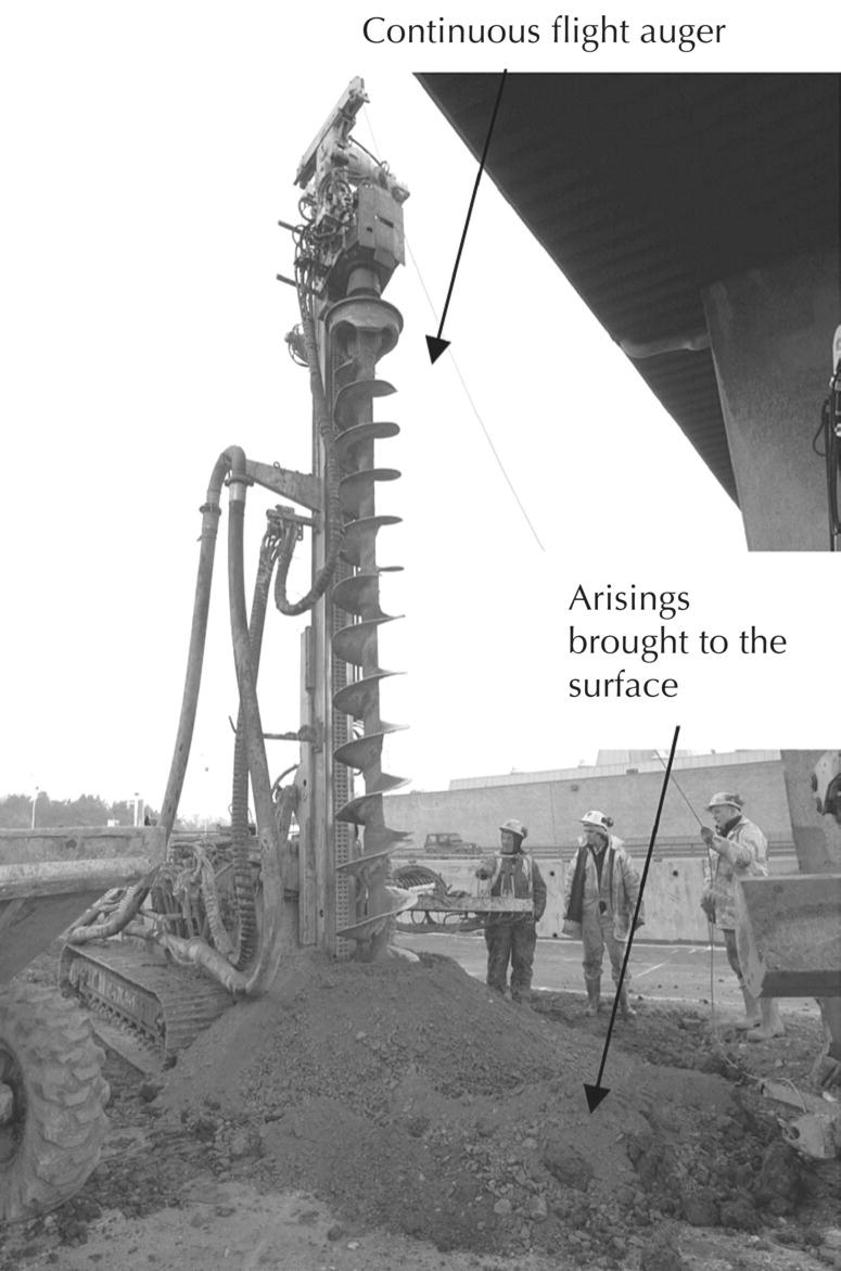
Continuous flight auger piles
Continuous flight auger (CFA) piles are formed using hollow stem auger boring techniques. The auger has a hollow central tube surrounded by a continuous thread. The helical cutting edge is continuous along the full length of the auger. The hollow tube that runs down the centre of the shaft is used for pumping concrete into the hole as the cutting device is withdrawn (Figure 3.15 and Photograph 3.4). As the CFA rig cuts into the ground, arisings are brought to the surface. The arisings allow the soil to be inspected at regular intervals, giving an indication of the strata below the surface. Once the rig has produced a bore to a calculated depth, through known strata, the auger is steadily withdrawn as concrete is pumped under pressure through the hollow stem. The concrete simultaneously fills the void left by the auger as it is extracted. The concrete reinforcement cage is pushed into the bore after the pile has been concreted. Spacers are fixed to the side of the reinforcement so that the cage is positioned centrally in the pile and adequate concrete cover is maintained around the reinforcement. CFA piles are suitable for a range of ground conditions, are relatively quiet, and cause less noise and vibration when compared to hammer‐driven piles; they can accommodate large working loads and are quick to install.

Figure 3.15 CFA piles.
Photograph 3.4 CFA.
(Source: http://www.roger‐bullivant.co.uk).
Bored displacement piles
Continuous helical displacement piles
Continuous helical displacement (CHD) piles are becoming a popular alternative to CFA piles. The displacement piles have the advantage that they do not produce arisings; this is particularly useful on contaminated sites. In most ground conditions, the CHD piles have enhanced load‐carrying capacity, compared with a CFA pile of similar dimensions. Due to the compaction of the soil, friction between the pile and the strata is increased. The increased strength gained in some ground conditions enables the pile length to be shortened, resulting in shorter installation times and more economical foundations.
The piles are formed using a multi‐flight, bullet ended shaft, which is driven by a high torque rotary head (Figure 3.16 and Photograph 3.5). This enables the ground to be penetrated without bringing any material to the surface (Figure 3.17). Some slight heaving of the surface may occur as the ground is compressed; however, this is normally negligible.

Figure 3.16 Components of CHD piles.

Figure 3.17 CHD piles.

Photograph 3.5 Continuous helical flight displacement piles.
(Source: http://www.roger‐bullivant.co.uk).
The pile is drilled to the calculated or proven depth; the shaft is then reversed and extracted while concrete is simultaneously pumped under pressure into the helical void that remains. Once the auger is totally extracted, reinforcement can be pushed into the concrete as a single bar or cage (Photograph 3.5).
Testing piles
Piles are often tested using dynamic load, sonic integrity or static load methods. These three methods are described briefly here.
Dynamic load methods
Dynamic load methods of testing are suitable for most types of pile, but are more frequently used on precast concrete or tubular steel piles. The test is commonly used on small piling works where the cost of static load testing cannot be justified. The test determines the loadbearing capacity of the pile, skin friction and end bearing. Other characteristics such as hammer energy transfer, pile integrity, pile stresses, driving and load displacement behaviour can also be determined.
To dynamically test a pile, it is struck by a hammer, using the piling rig. Two strain transducers and accelerometers (measures speed and acceleration) are firmly attached to the face of the pile near to the head of the pile. As the pile is struck, the equipment measures the force and acceleration of the pile. The information is relayed to the monitoring equipment. Once analysed, the data provides models of shaft friction distribution, bearing capacity and load settlement behaviour.
Sonic integrity testing
Sonic integrity testing is normally used on CFA, CHD or other piles foundations formed using in situ concrete. The integrity method is fast and reliable. A large number of piles can be tested in a single visit. The pile determines the reliability, morphology (form and composition) and quality of construction of the pile.
Before the pile can be tested, it must be sufficiently cured, free of latency and trimmed back to sound concrete. It is preferable to carry out the test at the final cut‐off level of the pile. A small hand‐held hammer is used to strike the pile. A series of low strain acoustic shock waves are sent through the piles. As the waves pass down the pile, the sound waves rebound where changes in impedance occur. The rebound (echo) is then recorded by a small accelerometer (instrument for measuring speed and acceleration), which is held against the pile head. The response is monitored and stored, and a graphical representation produced for immediate inspection (Photograph 3.6b).

Photograph 3.6 Piles – static load testing equipment.
(Source: http://www.roger‐bullivant.co.uk).
Static load testing
Static load testing is used to determine the displacement characteristics of a pile. All piles are suited to static load testing. Static load testing frames are assembled specifically for the test. Major piling contractors assemble frames capable of accommodating loads up to 4000 kN (Photograph 3.6).
A known load has to be applied in the form of kentledge (loaded test frame) or tension pile reaction. Load can also be applied by fixing a frame to piles already installed in the ground. Other piles can then be tested against the frame load. Once an adequate reaction has been provided (load), the test is carried out using a hydraulic jack and calibrated digital load cell. Time, load, temperature and displacement data are recorded.
Pile caps and spacing of piles
Piles may be used to support pad, strip or raft foundations. Commonly a group of piles is used to support a column or pier base. The load from the column or pier is transmitted to the piles through a reinforced concrete pile cap, which is cast over the piles. To provide structural continuity, the reinforcement of the piles is linked to the reinforcement of the pile caps through starter bars protruding from the top of the cast‐in‐place piles or through reinforcement exposed by breaking off the top concrete from precast piles. The exposed reinforcement of the top of the piles is wired to the reinforcement of the pile caps. Similarly, starter bars cast in and linked to the reinforcement of the pile caps protrude from the top of the pile caps for linking to the reinforcement of columns. Figure 3.18 illustrates typical arrangements of pile caps. The spacing of piles should be wide enough to allow for the necessary number of piles to be driven or bored to the required depth of penetration without damage to adjacent construction or to other piles in the group. Piles are generally formed in comparatively close groups for economy in the size of the pile caps to which they are connected. Photographs 3.7a–c shows the stages of the pile cap construction. As a general rule, the spacing, centre to centre of friction piles, should be not less than the perimeter of the pile, and the spacing of end‐bearing piles not less than twice the least width of the pile.
Figure 3.18 Concrete pile cap arrangements.


Photograph 3.7 (a) Top of concrete pile broken away to expose reinforcement. (b) Triple concrete pile arrangement ready to receive pile cap. (c) Pile cap reinforcement and formwork.
3.2 Ground stabilisation
There are a number of different methods that can be used for improving the general ground condition of a site. In many cases, improving the ground reduces the cost of foundations. Where the ground has been improved by compaction and consolidated, traditional foundation methods may be used rather than an expensive system of piles. Some sites which have been built up or are unstable may need to be improved, just to provide a sound hard standing so that heavy plant can operate on the site safely. Other sites require more permanent improvement, ensuring that the new building or structure and access to and around the structure remain stable.
Dynamic compaction
Dynamic compaction and consolidation using tamping systems can enhance the ground conditions up to considerable depths. The ground is consolidated by repeatedly dropping specially designed tampers into the ground. Two systems are commonly used. The first uses a flat‐bottomed tamper; the alternative, more modern method uses cone‐shaped tampers. Flat‐bottomed tampers can be slower and tend to create more noise and vibration than the cone system of tamping. Modern methods tend to use vertical guiders (or leaders) to control the fall and rise of the tamper (Photograph 3.8); with traditional methods the load (tamper) was simply attached to a cable. When lifting and lowering the weight, time had to be allowed for the tamper to stabilise.

Photograph 3.8 Dynamic compaction.
(Source: http://www.roger‐bullivant.co.uk).
Ground conditions suitable for dynamic compaction include natural granular soils, made‐up ground and former landfill sites. The technique can also be used as part of a more significant earthworks operation, where the ground is built up in layers, compacted and consolidated. Where fill is built up in layers, the fill may take the form of unmodified material (as previously excavated) or soils that are modified or stabilised using additives, such as quicklime and pulverised fuel ash (PFA) cement.
To achieve the desired effect, several passes may be required. Careful monitoring and testing is required; grid levels may need to be taken before and after each pass. Trial drops should be taken to determine the optimum treatment regime, monitor the imprint and depths, and measure pore water pressures, as necessary. To determine the allowable bearing capacity, accurate measurements are taken of the penetration achieved by application of particular energy (known load from a known height). Analysis of the levels can be used to calculate the amount of void closure and the degree of densification. Using dynamic compaction, bearing capacities of 50–150 kN/m2 can be achieved. Greater bearing capacities may be achievable, depending on the ground conditions.
Different shaped tamper heads are available with a variety of weights, depending on the degree of consolidation and compaction required (Figure 3.19). Figure 3.20 shows a typical pattern of work. Three passes are used in this example to achieve the required compaction and consolidation. Initial tamping is undertaken using a single pointed tamper; the tamper is up to 2.5 m long with a mass of 10 tonnes. The ground is tamped on a grid with the objective of densifying deep layers. Subsequent tamping is then undertaken using multi‐pointed tampers (Photograph 3.8). The multi‐point tamper improves ground consolidation at shallower depths (Figures 3.19 and 3.20).

Figure 3.19 Typical cone type tampers.
(Source: adapted from http://www.roger‐bullivant.co.uk).

Figure 3.20 Dynamic compaction.
(Source: adapted from http://www.roger‐bullivant.co.uk).
Vibro compaction
Vibro compaction (also known as vibro displacement or vibro replacement) uses large vibrating mandrels (vibrating shafts or rods) to penetrate, displace and compact the soil (Figure 3.21). When the mandrel is removed from the ground, the subsequent void is filled with stone. The mandrel is then forced back through the stone, further displacing and compacting the ground and stone. The method that produces stone columns in the ground compacts the surrounding strata, enhancing the ground‐bearing capacity and limiting settlement. Typical applications include support of foundations, slabs, hard standings, pavements, tanks or embankments. Soft soils, man‐made and other strata can be reinforced to achieve improved specification requirements, while slopes can be treated to limit the risk of slip failure. The allowable ground‐bearing capacities for low‐ to medium‐rise buildings and industrial developments are in the region of 100–200 kN/m2. Beneath tanks, embankments or slopes of 100 kN/m2 can be achieved. Ground conditions may allow heavier loads to be supported.


Figure 3.21 Vibro displacement – typical sequence.
The high‐powered mandrel penetrates the ground, in a vertical plane to the designed depth. When the mandrel is extracted, the resulting bore is filled with suitable aggregate or stabilised solids; these are compacted in layers of 200–600 mm increments. The shape of the mandrel (poker) tip is designed to ensure high compaction of the stone or stabilised soil column and surrounding strata. The taper on the mandrel causes increased densification of the strata.
Vibro displacement and compaction can be used in granular and cohesive soils. In granular soils, the ground‐bearing capacity is improved by the introduction of columns of compacted stone or stabilised soil, and the compaction and densification of the granular soil that surrounds each column.
Cohesive soils are not compacted in the same way that granular soils are. In clays the stone columns help to share and distribute the loads. The columns of stone carry the loads down the pile and distribute them through the strata; however, they are not end bearing. Where the density and consistency of the ground varies, the installation of stone columns helps to stabilise the ground, enhances loadbearing performance and makes the conditions more uniform, thus limiting differential settlement. The benefits of vibro compaction include:
- Buildings can be supported on conventional foundations (normally reinforced and shallow foundations).
- Work can commence immediately following the vibro displacement. Foundations can be installed straightaway.
- The soil is displaced. No soil is produced.
- Contaminants remain in the ground – reducing disposal and remediation fees.
- Economical, when compared with piling or deep excavation works.
- Can be used to regenerate brownfield sites.
- Can use reclaimed aggregates and soils.
Vibro flotation
Vibro flotation uses a similar process to vibro compaction, except that the vibrating poker has high‐pressure water jets at the tip of the poker. The water jets help to achieve the initial penetration into the ground. The advantage of this system is that the water jets help the vibrator penetrate hard layers of ground. A major disadvantage is that the system is messy and imprecise, thus rarely used.
Pressure grouting
In permeable soils, or soils where it is known that small cavities may be within the ground, pressure grouting may be used to fill the voids. Holes are drilled into the ground using mechanically driven augers. As the auger is withdrawn, cement slurry is forced down a central tube into the bore under pressure. Pressures of up to 70 000 N/mm2 can be exerted by the grout on the surrounding soil. The slurry contains cementous additives, such as PFA, microsilica, chemical grout, cement or a mixture. PFA is cheap and often used as a bulk filler to improve the bearing capacity of the ground. As the grout enters the void, it forces itself into the voids, cavities and fissures in the soils and rock. In weak soils, it will displace and compact the ground as it fills the voids. As the voids are filled, the ground becomes stiffer, more stable and water resistant. Pressure grouting can also be used around basements and coffer dams to reduce the hydrostatic pressure on the structure. To create a water‐resistant barrier, the bores and subsequent columns of grout are placed at close centres. PFA is generally used as the ground modification and stabilisation material, whereas the expensive chemical mixes (resin or epoxy mixes) or those containing microsilica are used to fill small voids and improve the ground’s water resistance.
Soil modification and recycling
Shortage of land in cities and towns, combined with a desire to bring redundant land back into use, has necessitated the need to improve ground conditions. Specialist companies have developed plant that is capable of modifying and stabilizing the ground relatively quickly. Mobile plant can cut into the ground and break it up, grade and crush the material and then combine it with additives before laying it to provide a more suitable surface. The additives used in soil stabilisation increase the strength of the soil, providing more workable materials which can be better compacted to maximise bearing capacity and minimise settlement. Soil stabilisation may be used to treat and neutralise certain contaminants or encapsulate the contaminants, removing the need for expensive removal and disposal.
3.3 Substructures and basements
Over the centuries, many buildings have been designed and constructed with substructures and basements. Traditionally, the basement was used for storage of goods and coal that were not prone to damp or damage from occasional flooding. Over time, as property values have increased and drainage has improved, many of these basements have been turned into living accommodation. The basements were usually built using engineering bricks, which provided a degree of resistance to ground water penetration. More recently it has become common to construct basements from reinforced concrete and/or dense blockwork, which is then tanked to prevent water from entering the building. Given suitable ground conditions, it is usually relatively economic to construct basements to buildings. This is especially true of high‐rise buildings, which require substantial substructure works to accommodate the dynamic forces on the structure. Deep excavations naturally lend themselves to several levels of accommodation below ground. These spaces will need to be lit using artificial light and ventilated with mechanical ventilation systems.
The foundation substructure of multi‐storey buildings is often constructed below natural or artificial ground level. In towns and cities, the ground for some metres below ground level has often been filled, over the centuries, to an artificial level. Filled ground is generally of poor and variable bearing capacity and is not good material on which to place foundations. It is generally necessary to remove the artificial ground and construct a substructure or basement of one or more floors below ground. Similarly, where there is a top layer of natural ground of poor and variable bearing capacity, it is often removed and a substructure formed. Where there are appreciable differences of level on a building site, a part or the whole of the building may be below ground level as a substructure.
The natural or artificial ground around the substructure is usually permeable to water and may retain water to a level above that of the lower basement level or floor of a substructure. Groundwater in soil around a substructure will impose pressure on both the walls and the floor of a substructure. This is known as hydrostatic pressure and is sufficiently strong to penetrate small cracks and joints. The cracks in the construction may be due to construction joints that are not watertight, shrinkage or movement of dense concrete walls and floors, and even dense, solidly built brick walls may allow water to penetrate. To limit the penetration of groundwater under pressure, it is usual practice to build in waterstops across construction and movement joints in concrete walls and floors, and to line walls and concrete floors with a layer of impermeable material in the form of a waterproof lining like a tank, hence the term ‘tanking to basements’. Typical basement tanking methods are illustrated in Figures 3.22 to 3.25.
Figure 3.22 Type A: internal basement tanking system.

Figure 3.23 Type A: external basement tanking system – with blockwork protection.

Figure 3.24 Type A: external basement tanking system – with protective board.
(Source: adapted from http://www.uk.graceconstruction.com).
Figure 3.25 Type B: waterproof concrete basement.
Another approach is to accept that there will be some penetration of groundwater through the external concrete wall, but not to allow this water into the usable part of the basement (Figure 3.26). Cavity walls are constructed with an external wall that retains the soil (the structural wall), a clear cavity that is drained at the bottom and an internal wall that provides a dry surface. Water that manages to penetrate the external structure runs down the external face of the cavity and is guided through channels to a sump where it is pumped out of the building. The external structural wall can be constructed of dense reinforced concrete with waterstops, or can be formed using contiguous, secant or steel piles (Figures 3.26 and 3.27).
Figure 3.26 Type C: traditional drained cavity basement.
Figure 3.27 Type C: cavity drain formed using high‐density studded polyethylene sheets
(Source: adapted from http://www.riw.co.uk).
The design of a basement is dependent on use, site conditions, construction conditions and waterproofing system. Table 3.1 provides a brief summary of the types of construction that are suitable for different basements.
Table 3.1 Type and level of protection required to suit use of basement
Source: Adapted from BS 8102:1990, BSI.
| Grade of construction | Use of basement | Level of performance and conditions required | Type of basement construction | Comment |
| Grade 1. Basic utility rooms | Plant rooms, car park | Some seepage and some damp patches may occur (tolerable), >65% relative humidity, 15–32 °C temperature | Reinforced concrete to BS 8110 Type B structure | Check that the groundwater does not contain chemicals. Some chemicals may degrade or have other deleterious effects on the structure and internal finishes. |
| Grade 2. Improved utility | Workshops and plant rooms, retail storage areas | No water penetration or seepage, but moisture vapour is tolerable, 35–5% relative humidity, <15 °C storage, up to 42 °C for plant rooms | Type A internal tanking system Type B to BS 8007 Watertight concrete | Good supervision of all stages of construction is necessary to ensure watertight construction. Membranes should be applied in multiple layers and lapped joints. |
| Grade 3. Habitable | Ventilated residential and working areas, e.g. offices, restaurants and leisure centres | Dry environment, tightly controlled, 40–60% relative humidity, 18–29 °C temperature, depending on use | Type A internal tanking system Type B to BS 9007 Monolithic concrete structure Type C to BS 8110 Drained cavity system | Good supervision of all stages of construction is necessary to ensure watertight construction. Membranes should be applied in multiple layers and lapped joints. |
| Grade 4. Special | Archives, paper stores and computer rooms | Controlled environment that is totally dry, 35–50% relative humidity, 13–22 °C temperature | Type A Internal tanking system Type B to BS 8007 Monolithic concrete structure, combined with vapour proof membrane Type C Drained cavity system. Ventilated wall cavity and vapour barrier to inner skin and floor protection | Good supervision of all stages of construction is necessary to ensure watertight construction. Membranes should be applied in multiple layers and lapped joints. |
Brief description of basement types.
Type A – tanking membrane. Waterproof membrane, formed out of mastic asphalt, bitumen, rubber/bitumen compound, bonded sheet membranes, Bituthene, or polymer modified bitumen, is either applied externally, internally or sandwiched between the basement walls. Bentonite clay and bentonite day sheets are also becoming common.
Type B – monolithic concrete. The structure itself provides the necessary waterproofing. The structure is formed with dense reinforced concrete, water bar is often used at construction joints, and additives may be introduced to the concrete to make it denser and more water resistant.
Type C – drained cavity. It is anticipated that water will penetrate the external structure. An internal skin of blockwork or concrete (with drainage former) is used to form a cavity. Water that enters the structure is drained off and pumped out of the building.
Waterstops to concrete walls and floors
Dense concrete, which is practically impermeable to water, would by itself effectively exclude groundwater (Figure 3.25). However, in some situations, it is difficult to prevent movement and the formation of cracks caused by shrinkage, structural, thermal and moisture movement. As concrete dries out and sets, it shrinks, and this inevitable drying shrinkage causes cracks, particularly at construction joints, through which groundwater will penetrate.
Waterstops
As a barrier to the penetration of water through construction joints and movement joints in concrete floors and walls underground, it is usual practice to either cast 4 (PVC) waterstops against and across joints or to cast rubber waterstops into the thickness of concrete. The first method is generally used where water pressure is low, and the alternative, second method where water pressure is high. The first method is the most economical as it merely involves fixing the PVC stops to the formwork. Movement joints are formed right across and up the whole height of large buildings and filled with an elastic material that can accommodate the movement due to structural, thermal and moisture changes. These movement joints are formed at intervals of not more than 30 m.
Movement joints are formed in the main to accommodate thermal movement due to expansion and contraction of long lengths of solid structure and at angles and intersections right across the width and up the whole height of buildings, including floors and roofs. In effect, movement joints create separate structures each side of the joint. In framed structures, movement joints are usually formed between a pair of columns and pairs of associated beams.
PVC waterstops, illustrated in Figure 3.28, are fixed to the inside face of the timber formwork to the outside face of walls and to the concrete base under reinforced concrete floors, so that the projecting dumbbells are cast into the concrete floors and walls. The large dumbbell in the centre of the waterstops for movement joints is designed to accommodate the larger movement likely at these joints. Provided the concrete is solidly consolidated up to the stops, this system will effectively act as a waterstop. At the right‐angled joints of waterstops, preformed cross‐over sections of stops are heat welded to the ends of straight lengths of stop. Rubber waterstops are cast into the thickness of concrete walls and floors, as illustrated in Figure 3.29. Plain web stops are cast in at construction joints and centre bulb stops at expansion joints. These stops must be firmly fixed in place and supported with timber edging to one side of the stop, so that concrete can be placed and compacted around the other half of the stop without moving it out of place. At the junction of the joints, hot vulcanising joins the stops. Hot vulcanising is where a hot iron heats the PVC, and as the PVC melts the two ends merge together.
Figure 3.28 PVC waterstops.
Figure 3.29 Rubber waterstops.
For waterstops to be effective, concrete must be placed and firmly compacted up to the stops, and the stops must be secured in place to avoid them being displaced during placing and compacting of concrete. Waterstops will be effective in preventing penetration of water through joints, provided they are solidly cast up to or inside sound concrete and there is no gross contraction at construction joints or movement at expansion joints.
Tanking
The term ‘tanking’ is used to describe a continuous waterproof lining to the walls and floors of substructures, to act as a tank to exclude water.
Mastic asphalt
The traditional material for tanking is mastic asphalt, which is applied and spread hot in three coats to a thickness of 20 mm for vertical work and 30 mm for horizontal work. Joints between each layer of asphalt in each coat should be staggered at least 75 mm for vertical work and 150 mm for horizontal work with the joints in succeeding coats. Angles are reinforced with a two‐coat fillet of asphalt. Asphalt tanking should be applied to the outside face of structural walls and under structural floors so that the walls and floors provide resistance against water pressure on the asphalt and the asphalt keeps water from the structure. Figure 3.30 is an illustration of asphalt tanking applied externally to the reinforced concrete walls and floor of a substructure or basement. The horizontal asphalt is spread in three coats on the concrete base and over pile caps and extended 150 mm outside of the junction of the horizontal and vertical asphalt and the angle fillet. The horizontal asphalt is then covered with a protective screed of cement and sand 50 mm thick. The reinforced concrete floor should be cast on the protective screed as soon as possible, to act as a loading coat against water pressure under the asphalt below.
Figure 3.30 Mastic asphalt tanking applied externally to the reinforced concrete walls and floor of a substructure or basement.
When the reinforced concrete walls have been cast in place and have dried, the vertical asphalt is spread in three coats and fused to the projection of the horizontal asphalt with an angle fillet. A half brick protective skin of brickwork is then built, leaving a 40 mm gap between the wall and the asphalt. The gap is filled solidly with mortar, course by course, as the wall is built. The half brick wall provides protection against damage from backfilling and the mortar filled gap ensures that the asphalt is firmly sandwiched up to the structural wall. In Figure 3.30, the asphalt tanking is continued under a paved forecourt. Where vertical asphalt is carried up on the outside of external walls, it should be carried up at least 150 mm above ground to join a damp‐proof course (dpc).
Figure 3.31 is an illustration of mastic asphalt tanking to a concrete floor and loadbearing brick wall to a substructure. The protective screed to the horizontal asphalt and protecting outer wall and mortar filled gap to the vertical asphalt serve the same functions as they do for a concrete substructure. As a key for the vertical asphalt, the horizontal joints in the external face of the loadbearing wall should be lightly raked out and well brushed when the mortar has hardened sufficiently.

Figure 3.31 Mastic asphalt tanking applied to a concrete floor and loadbearing brick wall to a substructure.
Where the walls of substructures are on site boundaries and it is not possible to excavate to provide adequate working space to apply asphalt externally, a system of internal tanking may be used. The concrete base and structural walls are built, the horizontal asphalt is spread on the concrete base and a 50 mm protective screed spread over the asphalt. Asphalt is then spread up the inside of the structural walls and joined to the angle fillet reinforcement at the junction of horizontal and vertical asphalt. A loading and protective wall, usually of brick, is then built with a 40 mm mortar filled gap up to the internal vertical asphalt. The internal protective and loading wall, which has to be sufficiently thick to resist the pressure of water on the asphalt, is usually one brick thick. A concrete loading slab is then cast on the protective screed to act against water pressure (also called hydrostatic pressure) on the horizontal asphalt. An internal asphalt lining is rarely used for new buildings, because of the additional floor and wall construction necessary to resist water pressure on the asphalt. Internal asphalt is sometimes used where a substructure to an existing building is to be waterproofed.
Service pipes for water, gas and electricity and drain connections that are run through the walls of a substructure that is lined with asphalt tanking, are run through a sleeve that provides a watertight seal to the perforation of the asphalt tanking and allows for some movement between the service pipe or drain and the sleeve. The sleeve is coated with asphalt that is joined to the vertical asphalt with a collar of asphalt, which runs around the sleeve, as illustrated in Figure 3.32.

Figure 3.32 Four stages in forming an asphalt collar around pipe.
Asphalt that is sandwiched in floors as tanking has adequate compressive strength to sustain the loads normal to buildings. The disadvantages of asphalt are that asphalting is a comparatively expensive labour‐intensive operation and that asphalt is a brittle material that will readily crack and let in water if there is differential settlement or appreciable movements of the substructure. In general, the use of asphalt tanking is limited to substructures with a length or width of not more than about 7.5 m to minimise the possibility of settlement or movement cracks fracturing the asphalt.
Bituminous membranes
As an alternative to asphalt, bituminous membranes are commonly used for waterproofing and tanking to substructures. The membrane is supplied as a sheet of polythene or polyester film, or sheet bonded to a self‐adhesive rubber/bitumen compound or a polymer modified bitumen. The heavier grades of these membranes are reinforced with a meshed fabric sandwiched in the self‐adhesive bitumen. The membrane is supplied in rolls about 1 m wide and 12–18 m long, with the self‐adhesive surface protected with a release paper backing. The particular advantage of these membranes is that their flexibility can accommodate small shrinkage, structural, thermal and moisture movements without damage to the membrane. Used in conjunction with waterstops to concrete substructures, these membranes may be used as tanking (see Figures 3.22 to 3.33).
Figure 3.33 Bituminous sheet membrane tanking.
The surface to which the membrane is applied by adhesion of the bitumen coating must be dry, clean and free from any visible projections that would puncture the membrane. The membrane is applied to a dry, clean float finished screed for floors and to level concrete wall surfaces on which all projecting nibs from formwork have been removed and cavities filled. The vertical surface to which the membrane is to be applied is first primed. The rolls of sheet are laid out, the paper backing removed and the membrane laid with the adhesive bitumen face down or against walls and spread out and firmly pressed on to the surface with a roller. Joints between long edges of the membrane are overlapped 75 mm and end joints 150 mm, and the overlap joints are firmly rolled in to compact the join. Laps on vertical wall surfaces are overlapped so that the sheet above overlaps the sheet below. At construction and movement joints, the membrane is spread over the joint with a PVC or rubber waterstop cast against or in the concrete.
Bitumen membranes are formed outside structural walls and under structural floors, as illustrated in Figure 3.33, with an overlap and fillet at the junction of vertical and horizontal membranes. To protect the vertical membrane from damage by backfilling, a protective concrete or half brick skin should be built up to the membrane. At angles and edges, a system of purposely cut and shaped cloaks and gussets of the membrane material is used over which the membrane is lapped, as illustrated in Figure 3.34. To be effective as a seal to the vulnerable angle joints, these overlapping cloaks and gussets must be carefully shaped and applied. The effectiveness of these membranes as waterproof tanking depends on dry, clean surfaces free from protrusions or cavities, and careful workmanship in spreading and lapping the sheets, cloaks and gussets.
Figure 3.34 Internal angle cloaks to bituminous membrane.
Cavity tanking
Cavity drain structures make allowances for the small amount of water that may pass through the external wall. The basement is constructed with two walls forming a void between the external and internal leaf, and a cavity is formed in the walls around the basement and below the floor (Figure 3.35). Traditionally, cavities were formed with floor tiles, which created a void, and two separate leafs of masonry walling. Nowadays, rolls of studded 1 mm thick polyethylene are used, with raised studs (domes), which stand between 5 and 20 mm from the surface, depending on the manufacturer and purpose. The sheets of polyethylene, which come in rolls 20 m long by 1.4 m wide, are applied to the structural walls and floors to form a very small but effective void. The sheets are fixed to the wall using an effective plug and screw system, and then permanently held and protected by a concrete screed floor and in situ concrete wall. Any water that penetrates through the external wall or floor is guided to drainage channels, where it is then pumped out of the building.

Figure 3.35 Drained cavity system.
If the water flow is expected to be relatively high, a sealed cavity system is used. All of the water that penetrates the wall flows, under gravity, to a sump pit where it is then pumped away. In existing buildings, where the walls of a basement are damp and not subject to water flow, a ventilated cavity system may be used. The cavity helps to keep the damp surface away from the internal wall and wall finishes. Moisture on the internal face of the wall will evaporate and the ventilation system guides the moist air out of the structure (Photograph 3.9 shows a ventilated and sealed drain cavity applied to a wall).
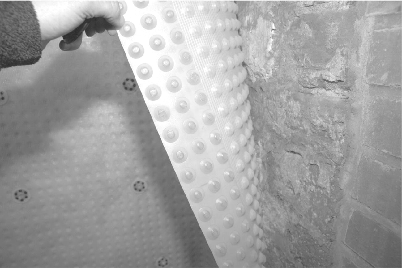
Photograph 3.9 Polypropylene ventilated cavity drain sheet applied to brick wall to control damp. The sealed cavity drain allows water to flow to a sump where it is pumped away.
Basement walls
There is often insufficient space to provide for the basement excavation and adequate batter so that the basement walls can be constructed out of the ground. It is becoming more common for deep basements to be constructed using diaphragm walls, with the aid of large clam grabs and bentonite slurry, and auger‐bored piled walls using secant, interlocking and contiguous piles.
Contiguous piles
With the development of CFA piling rigs, bored piles are becoming more common as a form of permanent wall and foundation. Contiguous piles (Figures 3.36 and 3.37a) are formed by drilling bored piles at close centres. Piles vary in diameter from 300 to 2400 mm, although piles greater than 1200 mm are rarely used. A small gap is left between each pile; typically this ranges between 20 and 150 mm (Photograph 3.10). The size of the gap depends on the soil strength. The gaps may be filled to provide a more water‐resistant structural concrete facing wall. The use of CFA rigs to form the piles limits the depth of pile to 30–55 m, depending on the type of rig. In practice, walls are usually constructed to a maximum of 25 m, although some piles may be driven much deeper to provide vertical load capacity. A ring beam is cast along the top of the piles linking all of the piles together; this provides extra rigidity and strength and helps to distribute any loads placed on top of the piles. Ground anchors can also be used to help resist the overturning forces caused by the surrounding strata and hydrostatic pressure. Grout is normally forced through the anchor to tie it securely into the ground. Where the area surrounding the retaining structure accommodates roads, structures or other property, grout may be forced into the ground to produce a positive pressure on the ground, which counteracts the possibility of settlement caused by the excavation of the basement and movement of the retaining wall. The excavation of the basement may cause settlement due to the vibration, which causes the surrounding ground to compact. Also, as the surrounding ground applies its load on the retaining wall, some slight movement will occur. Vibration and movement of the retaining wall will result in settlement of the surrounding ground; the pressure exerted by pressurised grout can be used to remove the potential of settlement.

Figure 3.36 Secant, interlocking and contiguous piles. Section through an anchored‐bored pile which, subject to spacing, can be used to form secant, interlocking and contiguous retaining walls.


Figure 3.37 Contiguous and secant piles.
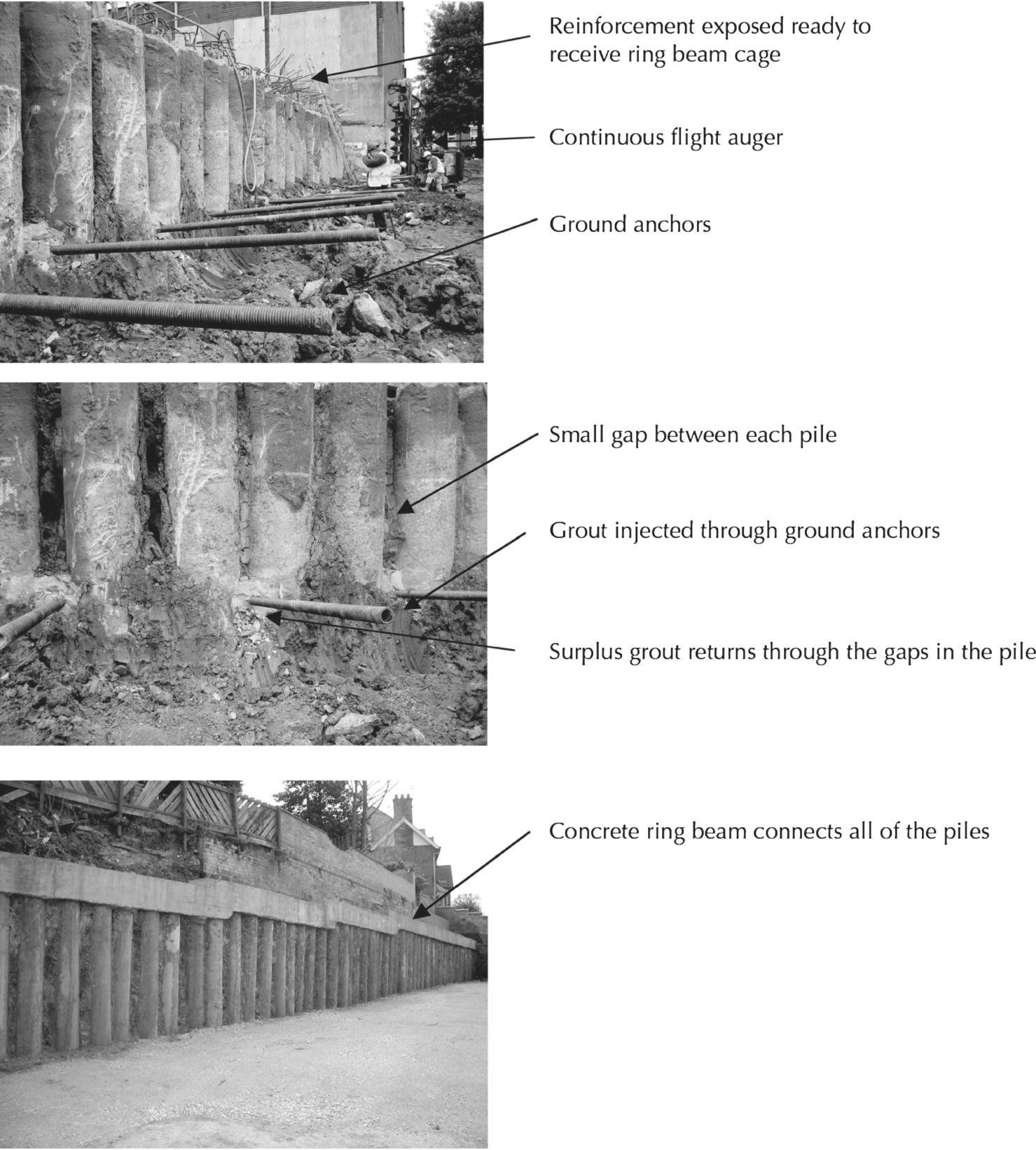
Photograph 3.10 Contiguous piles and ground anchors.
(Source: http://www.roger‐bullivant.co.uk).
Secant piles
Secant piles consist of overlapping and interlocking piles (Figures 3.37b–e and Photograph 3.11). Female (primary) piles are bored using CFA rigs and cast first. The secondary male piles are then drilled, secanting (cutting into) into the female pile. The system is often used in the construction of deep basement walls. Secant walls are often considered to be a more economical alternative to diaphragm walls.
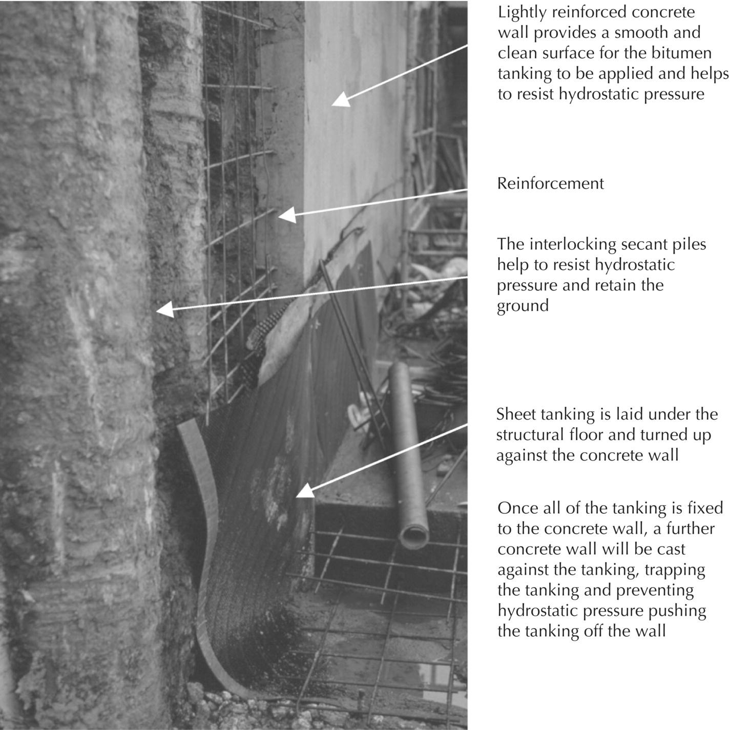
Photograph 3.11 Secant piling and internal tanking.
(Source: courtesy of D. Highfield).
Depending on the type of secant pile construction, either one or both piles are reinforced to resist the lateral loads. When the secant wall is in place, the excavated face can be covered with a layer of structural concrete. The concrete can be either sprayed or cast against the wall, providing a fair‐faced concrete finish. A reinforced concrete ring beam connects all of the piles together, improving the structural stability of the wall. The beam will also help to distribute any loads placed on top of the wall. The depth of the wall is usually limited to 25 m; however, it is possible to construct secant walls to a depth of 55 m. Multi‐storey basements are usually stabilised by ground anchors and cross‐bracing to resist lateral forces. Secant piles can be constructed as hard/soft, hard/firm or hard/hard walls.
Hard/soft secant piles
For hard/soft piles, the female piles, which are cast first, are constructed of a soft pile mix; this usually takes the form of a cement and bentonite mix or cement, bentonite and sand mix. The mix has a weak characteristic strength of 1–3 N/mm2. The female piles are used as a water‐retaining structure rather than a loadbearing column. Soft piles can retain up to 8 m head of groundwater. The unreinforced soft pile is not commonly used as a permanent wall material. As the bentonite and cement mix dries, it will shrink and crack, losing its water‐resisting properties. Some soft piles have been designed to retain their water‐resisting properties for the life of the structure; often this necessitates the mix remaining hydrated throughout the life of the building.
Hard/firm secant piles
In the hard/firm pile arrangement, the female pile has a characteristic strength of 10–20 N/mm2; during the wall’s construction, the strength of the pile is held low by adding a retarding agent to the concrete mix (Figure 3.37c). Female piles are usually designed to hit their target strength within 56 days rather than the more typical 28 days. Obviously, such practice ensures that the construction of the male pile is easier as the auger has to exert less force when secanting the female pile. Piles usually overlap a minimum of 25 mm.
Hard/hard secant piles
With hard/hard secant piles, both male and female piles are cast with full strength concrete and both are fully reinforced. The female piles are cast first and a high‐torque‐cutting casing is used to drill through the female pile. The reinforcement in the female pile is positioned so that the rig does not cut through it when boring the male pile. The depth of overlap is usually about 25 mm; considerable care is required to ensure that this is maintained along the full length of the pile. I‐section beams can also be added to the pile to further increase the lateral strength of the wall (Figure 3.37e).
Diaphragm walls
Diaphragm walls are formed by excavating a segmented trench to form a continuous wall (Figure 3.38). While the deep trench is being excavated, it is filled with bentonite slurry (supporting fluid). The slurry fills the trench and exerts pressure on the sides of the excavation, thus preventing the excavation walls collapsing. The excavation is carried out using a clamshell grab, which digs the material out through the bentonite slurry. The width of the wall is determined by the width of the grab. The diaphragm wall is cast in the ground. Using a tremie tube of about 200 mm diameter, the concrete is fed into the trench and placed in position. As the concrete settles at the base of the excavation, the bentonite slurry is displaced, drawn out of the excavation and cleaned for reuse. The disposal of bentonite at the end of the operation is expensive, as the mixture is treated as a contaminated material. The diaphragm wall is constructed in alternate panels, usually around 5 m long. The excavators are usually guided by shallow concrete beams that are cast so that the beam faces form the desired position of the wall. Diaphragm walls have been constructed to depths of 120 m; however, there are some practical difficulties when attempting to splice and link the reinforcement cages over such depths.
Figure 3.38 Diaphragm walls, plan sections.
The joints between each section can be cast using steel tubes or interlocking junctions to reduce the ingress of water through the joints (Figures 3.38b and c). The hydrofraise machine is used to cut an interlocking surface into the previously cast segment of wall (Figure 3.38d). Interlocking precast concrete sections can also be used. Once the precast concrete sections are in place, grout is used to fill any remaining joints.
Adding basements to existing buildings
In urban areas, it may be difficult or not possible to extend an existing property above ground due to space restrictions and/or town planning policy. Thus the only way to provide additional space is to go down into the ground. This is, of course, not without a number of challenges relating to, for example; ground conditions and groundwater pressure; the position of existing services; the condition and position of existing foundations, including those of adjoining/neighbouring properties; legal conditions relating to the property; town planning policy; access for conducting the work safely; and cost of the work. This is a specialist area in which some architects, building surveyors and contractors have expert knowledge and expertise. The primary concern will be related to the practicalities of conducting the building work without damaging neighbouring properties or causing nuisance; for example, by the transfer of sound from the new basement to adjoining properties.