
5
Structural Timber Frames
Structural timber frames are a popular choice for relatively low‐rise building of one to two storeys and increasingly popular for mid‐rise buildings (three to five storeys). More recently, structural timber frames have been used for buildings of up to nine and ten storeys high. The advantages of the structural timber frame are the speed of erection of the pre‐cut timber members and ease of fixing. Timber has inherent fire resistance and it is a sustainable material (carbon neutral). Structural timber frames may comprise seasoned timber, such as oak columns and beams, engineered timber components, or a mix of timber and engineered timber.
5.1 Functional requirements
The functional requirements of a structural frame are:
- Strength and stability
- Durability and freedom from maintenance
- Fire safety
Strength and stability
The strength of timber varies with species and is generally greater with dense hardwoods than less dense softwoods. Strength is also affected by defects in timber such as knots, shakes, wane and slope of the grain of the wood. The strength and stability of a structural timber frame depends on the combination of elements, such as columns and beams and the rigidity of the connections. Simple calculations will help to establish the size of columns and beams. Connections tend to follow a tradition of using a combination of nails, screws and bolts. Factory produced assemblies will be joined by mechanical connections.
Stress grading of timber
There are two methods of stress grading: visual grading and machine grading:
- Visual grading. Trained graders or computer software determine the grade of a timber by visual examination in the timber mill. This is to assess the effect on strength of observed defects such as knots, shakes, wane and slope of grain. There are two visual grades, general structural (GS) and special structural (SS). In SS, the allowable stress is higher than that in GS timber.
- Machine grading. Timbers are subjected to a test for stiffness by measuring deflection under load in a machine that applies a specified load across overlapping metre lengths to determine the stress grade. This mechanical test, premised on the fact that strength is proportional to stiffness, is a more certain assessment of the true strength of a timber than a visual test. The machine grades, which are comparable to the visual grades, are machine general structural (MGS) and machine special structural (MSS). There are, in addition, two further machine grades: M50 and M75. The stress of M50 lies between MGS and MSS, and M75 is the highest stress grade in the series.
Stress‐graded timbers are marked GS and SS at least once within the length of each piece for visually graded timber, together with a mark to indicate the grader or company. Machine‐graded timber is likewise marked MGS, M50, MSS and M75 together with the BS Kitemark and the number of the British Standard, 4978. Approved Document A provides practical guidance to meet the requirements of the Building Regulations for small buildings, and includes tables of the sizes of timber required for floors and roofs, related to load and span.
Durability and freedom from maintenance
The durability of timber is determined by careful specification and selection of seasoned timber together with careful detailing to avoid the possibility of rot. As a general rule, hardwood timbers are more durable than softwood timbers. Softwood will usually require some form of surface protection to increase its durability, such as paint, stain or impregnation with a preservative. Some hardwoods, such as oak, can be left to weather naturally without surface protection. Careful detailing can also help to avoid the possibility of wet or dry rot, as discussed later.
Fire safety
There is a misconception that timber framed buildings are not safe in a fire; this is incorrect. Structural fire safety is provided by passive protection, relating to the sizing, spacing and protection of timber. The reaction of timber in a fire has been extensively tested over the years, thus the behaviour is well known and buildings can be designed accordingly. Timber will char when exposed to flame, forming a protective layer and helping to preserve structural integrity. Large section timber beams and columns may be left without additional protection; however, the smaller section timber members of low rise timber framed houses will need to be protected. As a general rule, 30 minutes of fire protection can be achieved from components made of solid timber and glulam, by protecting it with a 12.5 mm (or 15 mm) thick layer of gypsum plasterboard. Additional fire resistance; for example, 60 minutes, can be achieved by using 25 mm thick gypsum plasterboard. For exposed timber structures, the fire resistance will depend on the charring characteristics of the timber components and the protection of fixings and joints. Exposed timber frames can be designed to incorporate sacrificial timber so that the timber exposed to flame will char and protect the inner, loadbearing material, from damage. The biggest threat to timber frame construction occurs during construction and refurbishment work, when unprotected elements are more susceptible to fire.
5.2 Timber
The word ‘timber’ describes wood that has been cut for use in building. Timber has many advantages as a building material. Timber is a comparatively lightweight material that is easy to cut, shape and join using hand‐ or power‐operated tools. As a structural material, it has good weight to cost, weight to strength and weight to modulus of elasticity ratios and coefficients of thermal expansion, density and thermal resistance. With sensible selection, fabrication and fixing, and adequate weather protection, timber is a reasonably durable material in relation to the life of most buildings. When sourced from sustainable forests, timber has excellent environmental credentials, and is considered carbon neutral during its lifetime. Softwood and hardwood are the terms used to classify timber.
It is rare to use timber in its natural state; however it is possible to do so. The term ‘roundwood construction’ refers to buildings that employ timber logs. The seasoned timber is used without any form of processing, other than cutting the tree trunks to size (and removing the bark) to create logs of the required length. Building with logs will create a unique low impact building when combined with natural walling materials such as unfired bricks and hemp lime. This form of construction tends to be used infrequently, as the timber logs vary in shape and it is not easy to calculate the strength of the structure.
Properties of timber
Up to two‐thirds of the weight of growing wood is due to water in the cells of the wood. When the tree is felled and the wood is cut into timber, this water begins to evaporate, and the wood gradually shrinks as water leaves the cell walls. As the shrinkage in timber is not uniform, the timber may lose shape and it is said to warp. It is essential that before timber is used in buildings, either it should be stacked for a sufficient time in the open air to allow most of the water in it to dry out or it should be artificially dried in a kiln. If unseasoned or wet timber is used in building, it will dry out and shrink, causing twisting of doors and windows and cracking at joints with plastered walls. This means that only seasoned timber should be used and that the timber should be protected from moisture on the building site, when stored and as work proceeds. The process of allowing, or causing, newly cut wood to dry out is called seasoning, and timber that is ready for use in building is said to have been properly seasoned.
Natural dry seasoning
When logs have been cut into timbers they are stacked either in the open or in an open‐sided shed. Timbers are stacked with battens between them to allow air to circulate around them and are left stacked until most of the moisture in the wood has evaporated. Softwoods are stacked for a year or two before they are sufficiently dried or seasoned. Hardwoods need to be stacked for much longer, for up to 10 years before they are seasoned. The lowest moisture content of timber that can be achieved by this method of seasoning is about 18%.
Artificial or kiln seasoning
Because of the great length of time required for natural dry seasoning and because sufficiently low moisture contents of wood cannot be achieved, artificial seasoning is used. After the wood has been converted to timber it is stacked in a kiln with battens between the timber. Air is blown through the kiln, the temperature and humidity of the air being regulated to affect seasoning more rapidly than with natural seasoning, but not so rapidly as to cause damage to the timber. If the timber is seasoned too quickly, it shrinks and is liable to crack and lose shape badly. To avoid this, it is common to allow timber to season naturally for a time and then to complete the process artificially.
Moisture content of timber
It is necessary to specify the moisture content of timber. Moisture content is stated as a percentage of the dry weight of the timber. The dry weight of any piece of timber is its weight after it has been so dried that further drying causes it to lose no more weight. This dry weight is reasonably constant for a given cubic measure of each type of wood and is used as the constant against which the moisture content can be assessed. Table 5.1 sets out moisture contents for timber. The moisture content of timber should be such that the timber will not appreciably gain or lose moisture in the position in which it is fixed.
Table 5.1 Moisture content of timber
Source: Column 1: Average moisture content likely to be attained under service conditions. Column 2: Moisture content which should not be exceeded in individual pieces at time of erection. Taken from BS 5268: Part 2:1996 (issue 2, May 1997).
| 1 | 2 | |
| Position of timber in building | % | % |
| External uses fully exposed | 20 or more | – |
| Covered and generally unheated | 18 | 24 |
| Covered and generally heated | 15 | 20 |
| Internal and continuously heated building | 12 | 20 |
Conversion of wood into timber
The method of converting wood to timber affects the timber in two ways: i) by the change of shape of the timber during seasoning; and ii) in the texture and differences in colour on the surface of the wood. Because the spring wood is less dense than the summer wood, the shrinkage caused when the wood is seasoned (dried) occurs mainly along the line of the annual rings. Circumferential shrinkage is greater than the radial shrinkage. Because of this, the shrinkage of one piece of timber cut from a log may be quite different from that cut from another part of the log. This can be illustrated by showing what happens to the planks of a log converted by the ‘through and through’ cut method shown in Figure 5.1. When the planks have been thoroughly seasoned, their deformation due to shrinkage can be compared by putting them together in the order in which they were cut from the log, as in Figure 5.1.

Figure 5.1 Conversion of wood into timber.
If the face of a timber is cut on a radius of the circle of the log, the cells of the medullary rays may be exposed where the cut is made. With many woods, this produces very pleasing texture and colour on the surface of the wood and it is said that the ‘figure’ of the wood has been exposed (Figure 5.1). Radial cutting of boards as shown is very expensive and is employed only for high‐class cabinet‐making and panelling timbers where the wood will be used decoratively.
Surface finishes for timber
Timber can be left unfinished or a protective decorative finish can be applied to the surface. Unfinished timber is sometimes used on buildings for aesthetic effect and to reduce the environmental impact and maintenance costs of applying finishes to the timber at regular intervals. Care is required in the selection and detailing of suitable timbers for a given location and degree of exposure. There are three types of applied surface finish for wood: paint, varnish and stains (see also Chapter 10). Paint and varnish are protective and decorative finishes that afford some protection against water and provide a decorative finish that can easily be cleaned. Paints are opaque and hide the surfaces of the wood, whereas varnishes are sufficiently transparent for the texture and grain of the wood to show. There is a wide range of stains available, from those that leave a definite film on the surface to those that penetrate the surface. Stains range from gloss through semi‐gloss to matt finish. The purpose of this finish is to give a selected uniform colour to wood without masking the grain and texture of the wood. Most stains contain a preservative to inhibit fungal surface growth. These stains are most effective on rough sawn timbers.
Decay in timber
Decay in timber is caused by fungal decay and insect infestation, both of which can be prevented through careful detailing and specification as well as through careful work both off and on the construction site. Insect attack will depend upon location, moisture content and temperature. Any one of a number of wood‐destroying fungi may attack timber that is persistently wet and has a moisture content of over 20%. Fungal decay is classified as being ‘dry’ or ‘wet’ rot.
Dry rot and its prevention
Dry rot is the most serious form of fungal decay and is caused by Serpula lacrymans, which can spread and cause extensive destruction of timber. Airborne spores of this fungus settle on timber, and if its moisture content is greater than 20%, they germinate. The spore forms long thread‐like cells that pierce the wood cells and use the wood as a food. The thread‐like cells multiply, spreading out long white thread‐like arms called mycelium, which feed on other wood cells. This fungus can spread many metres from the point where the spore first began to thrive, and is capable of forming thick greyish strands that can find their way through lime mortar and softer bricks. Timber that is affected by this fungus turns dark brown and shrinks and dries into a cracked powdery dry mass, hence the name dry rot. It is generally accepted that there is little risk of fungal decay in softwood if the timber is maintained at a moisture content of 20% or less.
Dry rot can be prevented through careful detailing to allow adequate ventilation and regular maintenance to prevent the moisture content of the timber from rising due to, for example, leaks in the building fabric or service pipes. Unseasoned timber must not be used and effort must be made during the construction work to keep seasoned timber dry. Buildings should be detailed to include horizontal and vertical dpcs and all underfloor areas to suspended timber floors and roof spaces must be adequately ventilated. Manufacturers and suppliers of timber‐framed buildings will detail their bespoke systems to minimise the risk of dry and wet rot occurring.
The cause of the persistent dampness that has raised the moisture content of timber above 20%, such as leaking gutters or water pipes, must be corrected. This may involve providing a new dpc, preventing moisture penetration through walls, repairing leaking roofs and plumbing, eliminating condensation, clearing the bridging of dpcs and improving ventilation, including the provision of additional airbricks, and so on. Timber, plaster, dust and debris that have been affected by the fungus or are in close proximity to it should be taken out of the building and be burnt immediately. The purpose of burning the affected timber is to ensure that none of it is used in the repairs and to kill any spore that might cause further rot. All walls and surrounding masonry should be cleaned and treated by surface application of masonry biocide; preservative plugs or pastes should be inserted into holes drilled into localised problem areas and/or irrigation of fungal solution inserted via holes drilled into the wall (PCA, 2008). Although the use of heat has been suggested as a means of sterilising masonry adjacent to the affected area, there is little reported evidence of the use and effectiveness of this. Fungicide fluids for treatment against dry rot in masonry are water‐based and normally require total saturation; due to the health and safety risks caused by the preservative, this should be avoided wherever possible. Preference should be given to the use of preservative plugs, paste or organic solvent‐based fungicidal products. Old lime plaster on which, or through which, the rot has spread should be hacked off and renewed. New timber used to replace affected timber should be treated with a wood preservative before it is fixed or built in.
Because dry rot is capable of spreading through other materials and attacking dry timber, eradication involves the replacement of all affected timber with pre‐treated timber and the treatment of adjoining timbers, brickwork, plasterwork and adjacent areas well away from the point of decay.
The following operations must be carried out in order to ensure that the fungus is completely eradicated:
- Locate and eliminate the dampness responsible for the attack.
- Cut out, remove from the site and burn all defective timbers in the vicinity of the attack. All apparently sound timber within 300 mm (HSE, 2001), or to provide a greater safety margin 600 mm (PCA, 2008), of defective timber should also be cut out, removed and burnt.
- Note that surface spraying of timbers will not prevent the spread of dry rot from infected timber.
- Carry out a thorough check of all other timbers within the building to which the fungus might have spread. This may involve removing flooring, ceilings, skirtings, architraves, wall panels, and so on.
- Strip off all wall plaster that may contain fungal strands to 300 mm beyond the observed limit of growth (HSE, 2001; PCA, 2008).
- Clean down all exposed masonry by wire brushing. Remove all stripped plaster, debris and dust from the site.
- Surrounding masonry should be cleaned and treated by surface application of masonry biocide, preservative plugs or pastes inserted into holes drilled into localised problem areas and/or irrigation of fungal solution inserted via holes drilled into the wall (PCA, 2008).
- Replace all timber that has been cut out with new, well‐seasoned timber that has been pre‐treated with fungicidal preservative.
Wet rot and its prevention
Wet rot is caused principally by Coniphora puteana, the cellar fungus, which occurs more frequently, but is less serious, than dry rot. Decay of timber due to wet rot is confined to timbers that are in damp situations such as cellars, ground floors without dpcs and timbers and joinery that is frequently in contact with moisture. The rot causes darkening and longitudinal cracking of timber and there is often little or no visible growth of fungus on the surface of timber.
Timber should not be built into or in contact with any part of the structure that is likely to remain damp. dpcs and dpms above and at ground level and sensibly detailed flashings and gutters to roofs and chimneys will prevent the conditions suited to the growth of wet rot fungus.
Wet rot is not as prolific as dry rot and the outbreaks are usually more localised; thus the treatment and eradication are simpler. It is usually only necessary to replace the affected timber with new pre‐treated timber. This combined with the elimination of the wet rot attack and removal of the original cause is normally sufficient.
A wet rot attack is remedied by cutting out the affected wood from the point of decay with a safety clearance, and splicing‐in new, preservative‐treated timber.
Attacks of wet rot are often caused by the breakdown of the protective paint finish, which allows rainwater to penetrate the timber and create suitable conditions for attack. The cause of wet rot on internal elements is usually water penetration through the roof, walls and leaking plumbing. It is essential that the source of the water or moisture is identified and eliminated.
Insect attack on wood
In the UK, the three types of insects that most commonly cause damage to timber are the furniture beetle, the death‐watch beetle and the house longhorn beetle. Timber which the larvae of these beetles have affected should be sprayed or painted with a preservative that contains an insecticide during early summer and autumn. These preservatives prevent the larvae changing to beetles at the surface of the wood, which helps to prevent further infestation.
Wood preservatives
Wood may be preserved as a precaution against fungal decay or insect attack. Current practice is based on the premise that prevention is better than cure. The two types of preservative in general use are water borne or organic solvent formulations, where water or a volatile solvent serves as a vehicle for the active fungicide or insecticide components. If timber decay it discovered, it is advisable to consult one of the many companies that specialise in its diagnosis and treatment. They will carry out a detailed survey and diagnosis of the timber decay and provide a treatment and eradication package backed by guarantee.
Treatment of insect attack
Where there are only a few insect exit holes and the insect attack is not advanced, it is recommended that the timber be treated with water‐based insecticide. The insecticide should be applied so that it minimises the exposure to people, pets and the environment. If the insect attack goes to the heart of the timber, the amount of organic solvent‐based treatment must match the degree of penetration. If the attack is widespread, a paste or injected solvent‐based formulations should be used and applied to all timbers. If the attack is localized. treatment need only be applied 300 mm beyond the area of the affected timber. The cure to both insect attack and mould growth is to remove the source of the damp condition and environment. Without the water content, the insects cannot survive and the mould cannot grow. Timbers that have been structurally weakened by insect attack must be treated with insecticide and strengthened. If the timber is beyond use and repair, it should be cut out, burnt and completely replaced with new, pre‐treated timber.
The primary control method to prevent insect infestation and fungal attack is to keep timber dry. Excessive use of even modern water‐based treatment is not recommended.
5.3 Modified and engineered timber products
Modified and engineered timber products are manufactured under factory conditions to produce products that are superior to wood. These comprise modified wood products, a range of wood structural panels, glue‐laminated beams (see Chapter 4), cross‐laminated timber (CLT) panels and engineered beams. Modified wood products primarily enhance the durability of timber. Engineered products involve the bonding together of timber using permanent adhesives (glues) to create products that offer structural advantages over natural timber. The primary functional requirements are durability, strength and stability, but some of these products also claim to have strong environmental credentials.
Modified wood products (MWPs)
It is possible to modify the properties of timber through impregnation, chemical treatment and/or heat treatment. This allows cheaper, less durable timbers to be used and modified into highly durable products that are less sensitive to moisture, UV, dimensional change, fungal and insect attack. The timbers most used include pine, poplar, eucalyptus and other fast growing varieties. Modified timber products may be used for flooring in wet areas and externally for cladding buildings. There are many process and products on the market, but the main approaches are:
- Impregnation: is achieved by using a liquid catalyst and vacuum pressure impregnation, with a drying temperature above 100 °C.
- Thermal modification: involves heating the timber to temperatures over 200 °C in an oxygen‐free environment. The lack of oxygen prevents the wood from burning. The heat treatment causes a chemical reaction within the timber, which ‘bakes’ the sugars and tannins in the wood. This makes the wood darker and harder and also makes it inedible to microbes and insects. This tends to result in a better performing product compared to pressure‐treated timber.
- Chemical modification: involves a variety of processes, the most well known being a process called acetylation. The wood is impregnated with acetic anhydride and reacts at high temperature. The process turns free hydroxyls, which absorb and release moisture and which are naturally present in the wood, into acetyl groups. This reduces the timber’s ability to absorb water, which makes it more dimensionally stable and very durable. Silicon‐based compounds are also used to similar effect.
Wood structural panels
Wood structural panels are precision engineered panels, manufactured under factory conditions. Wood structural panels comprise chipboard, MDF, plywood and orientated strand board (OSB). Plywood and OSB have similar characteristics in terms of strength and stiffness, but their composition is different. As a general rule, all of these products need to be protected from moisture during construction, and also after construction, to prevent expansion and damage from moisture/water ingress. Wood structural panels must be correctly installed and kept dry and ventilated. As a general rule, they should not be used in areas of high humidity.
Chipboard
Wood particles, saw dust, timber chips and shavings are glued together with an adhesive and hot pressed to create a rigid board. Chipboard, also known as particleboard, is a relatively cheap product, but tends to have limited use in construction, because it retains water and is prone to moisture damage. Three densities are available, normal‐, medium‐ and high‐density chipboard. Chipboard is usually protected with a decorative laminate, melamine or wood veneer to produce counter tops.
Medium‐density fibreboard (MDF)
Medium‐density fibreboard (MDF) is formed of fine wood dust and resin, which is then hot pressed into a board or formed into specific shapes, such as skirting board profiles. MDF can be manufactured to be fire and water resistant with the addition of specific resins. The material is easy to saw, drill and work with; however, this needs to be done in a well ventilated area and workers should wear eye protection and a face mask because the product may be harmful to health. The product is knot free and therefore well suited to internal joinery.
Plywood
Thin sheets of softwood or hardwood, called veneers, are positioned at right angles to one another and glued together using a hot press to form a cross‐laminated panel. The grain of each veneer is perpendicular to the adjacent layer. Plywood always comprises an odd number of layers so that it is balanced and hence less prone to bending, warping or shrinking. Plywood is used for roof and wall sheathing, as well as for flooring. The material will splinter when cut or sawn.
Orientated strand board (OSB)
Orientated strand board is manufactured in a similar way to plywood, although it is considered to be a more versatile alternative to plywood. Timber logs are ground into thin wood strands and dried. These strands are then mixed with adhesive and wax, formed into a mat and then hot pressed into panels. Wood fibres are positioned with opposing orientation to create a rigid and structurally strong board. OSB tends to be used for roofing and wall sheathing and also for flooring. OSB is easy to saw, drill, nail, screw and sand. Panels are available in a range of standard sizes (e.g. 1220 × 2440 mm and different thicknesses, 9, 11 and 18 mm). Panels can also be produced to bespoke sizes. OSB tends to react slower to moisture compared to plywood, but it is also slower to shed the moisture and hence prone to rot. OSB will expand quicker around the edges than the middle if it gets wet. There are two classifications, OSB/2 and OSB/3. The latter is designed and manufactured to cope with damp conditions.
Structurally insulated panels (SIPS)
Structurally insulated panels (SIPS) have been developed around the concept of composite (or sandwich) panels. The SIPS are composed of two faces, usually OSB/3, that ‘sandwich’ a rigid core of expanded polystyrene (EPS) or polyurethane (PU). This forms a lightweight panel that is easy to erect on site. The panels offer very good thermal insulation and airtightness in addition to inherent structural properties. SIPS offer a simple, dry form of construction that include the insulation and structure in one panel; rather then building the structure then adding the insulation. Panels tend to be around 140 to 175 mm thick and are manufactured in standard widths from 200 mm to 1200 mm, and lengths of up to 7.5 m. Bespoke widths can be made to order. The panels are used in floor, wall and roof construction, usually in conjunction with timber I beams and joists. A variety of proprietary products are available, some of which are designed specifically as cladding panels. SIPS may be used to achieve Passivhaus standards.
Cross‐laminated timber (CLT) panels
Cross‐laminated timber (CLT) panels are engineered timber products using kiln dried small sections of timber. Panels are manufactured in a similar way to glue‐laminated timber beams in a quality controlled factory environment. Small sections of timber are bonded together in layers with permanent adhesives to form large panels. Although the glues tend to have a high environmental impact, the glue content is very low, accounting for around 0.6% of the panel. Layers of timber (lamellas) are bonded perpendicularly to one another (longitudinal and transverse layers), hence the term cross‐laminated (or ‘crosslam’ or ‘X‐LAM’). The cross‐lamination gives the panel strength in two directions (dimensions) and helps to ensure the product retains its dimensional integrity when subjected to changing levels of humidity. Panels comprise a minimum of three layers of timber, rising to a maximum of seven layers, depending on the desired structural properties and overall thickness. The timber most commonly used is spruce, but other softwoods such as larch and some of the fir family are also used. The majority of the timber is kiln‐dried C24, with a small amount of C16 grade timber. The moisture content should be 12% (plus or minus 2%). Panel depth depends upon the number of layers used, ranging from 60 mm to around 340 mm.
Panels are manufactured in a range of sizes from 1.2 m to 3.5 m wide, typically 2.4 m wide for floor panels and 2.95 m for wall panels. Length may be up to 22 m, but more usually around 13 m to facilitate ease of transportation. The CLT panels are transported to site, craned into position and secured using screws and/or brackets. Panels should be kept dry on site, and if they do get wet (e.g. from a rain shower), they should be allowed to dry out prior to fixing and/or covering with another material. The size of the panels tends to be restricted by transportation to the site and access restrictions. This provides the potential for fast, dry onsite assembly.
Three grades of surface finish (visual quality) are available, depending on building function, whether or not the panels will be covered or left fair face and the desired aesthetic. The quality classifications are:
- Visible quality AB. Panels comprise a mixture of A and B quality lamellas that are planed and sanded on one side to give a visual quality suitable for residential buildings, offices and schools. The inherent finish can be left as supplied or a decorative finish (wash or varnish) may be applied.
- Visible quality BC. One side of the panel is planed and sanded. Typically used in industrial and commercial buildings where the visible quality may not be a major concern.
- Non‐visible quality C. This is the lowest visual quality and therefore the panels are commonly used in situations where they will be covered by, for example, a roof covering, plasterboard or render.
CLT panels are vapour permeable, which means that they can be used as part of a ‘breathing wall’ assemblage. They have a low environmental impact (carbon is stored within the product during its service life) and when the raw material is sourced from ecological, economical and socially responsible forests, they make a positive contribution to a green supply chain. The thermal conductivity is around 0.13 W/mK, which is similar to a lightweight concrete block. CLT has very good fire resistance, retaining its loadbearing capacity in a fire. The surface will char when exposed to flame and hence protect the inner core. The product can also positively contribute to acoustic insulation and airtightness, subject to appropriate detailing and fixing.
CLT panels are used in the construction of floors, walls and roofs. The smooth finish of the panels provides an inherent surface finish that does not require further treatment (unless required, such as a coloured wash). The panels are easy to fix into for first and second fix, using self‐tapping wood screws. CLT panels are used in the construction of high‐rise timber framed buildings, because of their strength and light weight.
All CLT panels must be kept dry during storage on site and during installation. They must be positioned above the level of the damp‐proof course (dpc) or damp proof membrane (dpm). CLT panels will require some form of protection, such as external cladding or render, if used for the external leaf of a wall. However, the panels are more commonly used for the inner leaf of walls and for internal partition walls. When used to form a floor, it is possible to achieve clear spans of around 8 m. Given the structural properties of CLT panels, it is possible to construct comparatively slim floors compared to more traditional approaches.
Engineered timber beams
Engineered timber beams are usually provided as an I section. The horizontal sections of the I are called flanges and the vertical element is the web. They are manufactured using wood composites and therefore can utilize young, easy to cut, sustainably sourced trees. Compared to traditional timber beams and joists, engineered timber beams are much lighter and use about one‐sixth of the material for the same structural strength. They are also dimensionally more precise and stable, as they do not dry and shrink as much as solid timber once the building is occupied. Engineered timber beams are used for floor joists (I‐joists) to the longer spanning I‐beams (e.g. for roof structures). They are also becoming common components of a range of prefabricated timber assemblies, such as wall, floor and roof panels. Manufacturers provide typical examples of spans and some provide interactive clear span tables for typical applications, such as floors.
Engineered bamboo products
Bamboo is a member of the grass family. As a fast growing and sustainable material, it offers benefits over slower growing timber. Bamboo exhibits similar characteristics to timber, and has long been used in construction; especially in countries where the product is abundant. The bamboo canes are referred to as culms. In its natural state, the irregularities in the bamboo culm make it challenging to connect individual sections for building. Engineered products offer greater potential for construction. The bamboo culm is processed in a factory to form a laminate composite. The culm is split, planed, bleached, caramelized and then glued and pressed to form a laminated sheet product. Engineered bamboo appears to have comparable structural properties to timber. Research and development is ongoing.
5.4 Timber framed walls
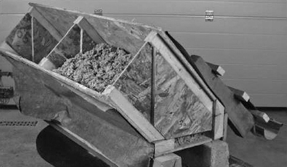
The construction of a timber framed wall is a rapid, clean, dry operation. Timbers can be cut and assembled with simple hand‐ or power‐operated tools, and once the wall is raised into position and fixed it is ready to receive wall finishes. A timber framed wall has adequate stability and strength to support the floors and roof of small buildings, such as houses. Covered with wall finishes, such as plasterboard, it has sufficient resistance to damage by fire, good thermal insulating properties and reasonable durability, providing it is well constructed and protected from decay. Timber framed houses can be constructed very quickly. Using off‐site prefabrication allows the erection of a house within a day, with roofing and external cladding completed soon afterwards. Alternatively, timber framed houses can be built from timber by carpenters or by self‐builders using a variety of proprietary systems (Photograph 5.1). There are a number of web sites that provide information on the design and specification of timber frame housing.
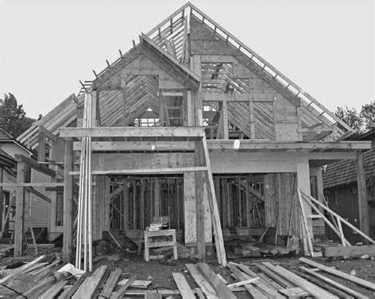
Photograph 5.1 Self‐build timber frame house under construction.
- TRADA: timber research and development association provides details, guidance, reports and updates; http://www.trada.co.uk
- Virtual site: provides details, 360 images and information on low‐carbon construction; http://www.leedsmet.ac.uk/teaching/vsite/
- Woodspec: guidance on designing and specifying timber frame building; http://www.woodspec.ie
Modern methods of timber frame construction were introduced into the UK in the 1960s. Timber frame construction offers flexible planning, energy‐efficient construction, economic use of materials and a wide range of finishes. Timber frame construction, especially when light cladding is used, is lighter than a comparable masonry structure, and in some instances the foundations can be designed to be smaller and hence less wasteful of materials. The dry construction is fast and there is no need to wait for wet trades to dry out before decorating. The high levels of thermal insulation make timber frame an attractive option, given stringent thermal requirements. The structure of timber frame buildings must be designed by a structural engineer to demonstrate structural stability of the structure and compliance with the Building Regulations. It is common to erect buildings to a height of two or three storeys, although it is possible to build higher (six to eight storeys) and still satisfy the Building Regulations.
Stability of timber framed buildings
The stability of a timber framed wall depends on a sound foundation on which a stable structure can be constructed. Figure 5.2 is an illustration of the base of a timber framed wall set on a brick upstand raised from a strip foundation. The 150 × 50 mm timber sole plate is bedded on a horizontal dpc; shot fired nail with sufficient anchorage is used to locate the sole plate, in exposed positions 13 mm bolts at 2 m centres built into the foundation to anchor the plate against wind uplift. As an alternative, the bolts may be shaped so that the bottom flange is built into the wall, run up on the inside face of the wall with a top flange turned over the top of the plate. Angle brackets may also be used to secure the sole plate.
Figure 5.2 Base of timber frame wall: fixing detail.
The upstand kerb of a concrete raft foundation serves as a base for the timber wall, with the anchor bolts set into the concrete kerbs and turned over the top of the sole plate. The vertical 150 × 50 mm studs are nailed to the sole plate at 400–600 mm centres with double studs at angles to facilitate fixing finishes (illustrated in Figure 5.3). Photograph 5.2 shows the sole plate, a packing piece of timber and the timber stud panel fixed to the floor.

Figure 5.3 Timber‐framed wall on raft foundation.

Photograph 5.2 Timber frame mounted on sole plate.
A timber stud wall consists of small section timbers fixed vertically between horizontal timber head and sole plates, as illustrated in Figure 5.4 and Photograph 5.3. The vertical stud members are usually spaced at centres of 400–600 mm to support the anticipated loads and to provide fixing for external and internal linings. The horizontal noggins fixed between studs are used to stiffen the studs against movement that might otherwise cause finishes to crack. A face of plywood sheeting is often applied to both sides of the insulated stud panel to provide considerable lateral stability.
Figure 5.4 Timber stud frame.

Photograph 5.3 Timber stud frame.
A timber stud wall has poor structural stability along its length because of the non‐rigid nailed connection of the studs to the head and sole plate, which will not strongly resist racking deformation. It must be braced (stiffened) against racking. As an internal wall or partition, a timber stud frame may be braced by diagonal timbers or by being wedged between solid brick or block walls. As an external wall, a timber stud frame may be braced between division walls and braced at angles where one wall butts to another, as illustrated in Figure 5.4. Diagonally fixed boarding or plywood sheathing fixed externally as a background for finishes, braces an external stud frame wall.
Because of its small mass, a timber frame wall has poor lateral stability against forces such as wind, which tend to overturn the wall. For stability along the length of the wall, connected external and internal walls or partitions will serve as buttresses. For stability up the height of the wall, timber upper floors and the roof connected to the wall will serve as buttresses. Buttressing to timber walls that run parallel to the span of floor joists and roof frames is provided by steel straps that are fixed across floor joists and roof rafters and fixed to timber walls in the same way that straps are used to buttress solid walls as previously described.
The usual method of supporting and fixing the upper floor joists to the timber wall frame is by using separate room height wall frames. The heads of the ground floor frames provide support for the floor joists on top of which the upper floor wall frame is fixed, as illustrated in Figure 5.5. The roof rafters are notched and fixed to the head of the upper floor wall frame. As an alternative, a system of storey height wall frames may be used with the top of the head of the lower frame in line with the top of the floor joists that are supported by a timber plate nailed to the studs, as illustrated in Figure 5.6. The upper frame is formed on the lower frame. The advantage of this system is that there is continuity of the wall frame and the disadvantage is that there is a less secure connection.
Figure 5.5 Support for floor joists.
Figure 5.6 Timber framed wall.
Figure 5.7 is an illustration of a two‐storey house with timber walls, floor and roof with a brick outer leaf, with the insulation filling the cavity rather than contained within the timber stud panels. It is rare to see timber frames constructed in this manner, but there is no reason why it cannot be done. Most timber frame panels are prefabricated, therefore site assembly is much quicker if the units come with insulation installed.

Figure 5.7 Timber framed cavity wall with brick outer leaf.
Timber or tile clad timber frame
The traditional weather envelope for timber walls is timber weatherboarding nailed horizontally across the stud frame. The weatherboards are shaped to overlap to shed water. Some typical sections of boarding are illustrated in Figure 5.8. The wedge section, feather edge boarding, is either fixed to a simple overlap or rebated to lie flat against the studs as illustrated. The shaped chamfered and rebated and tongued and grooved shiplap boarding is used for appearance, particularly when the boarding is to be painted. To minimise the possibility of boards twisting, it is usual practice to use boards of narrow widths, such as 100 and 150 mm.

Figure 5.8 Timber weatherboarding.
As protection against rain and wind penetrating the weatherboarding, it is usual to fix sheets of breather paper behind the weatherboarding. Breather paper serves to act as a barrier to water and at the same time allows the release of moisture vapour under pressure to move through the sheet. Instead of nailing weatherboarding directly to the studs of the wall frame, it is usual to fix either diagonally fixed boarding or sheets of plywood across the external faces of the stud frame. The boarding and ply sheets serve as a brace to the frame and as a sheath to seal the frame against weather. Figure 5.9 is an illustration of weatherboarding fixed to plywood sheathing with insulation fixed between studs.
Figure 5.9 Weather envelope.
Around openings to windows and doors, the weatherboarding and ply sheath may be butted to the back of window and door frames fixed to project beyond the stud frames for the purpose. At the head of the opening, the head of the frame may be reduced in depth so that the boarding runs down over the face of the frame. The weatherboarding butts up to the underside of a projecting cill. For extra protection, sheet lead may be fixed behind the weatherboarding and nailed and welted to window and door frames. At external angles, the weatherboarding may be mitred or finished square edged. An effective weathering is to fix a strip of lead behind the weatherboarding to form a sort of secret gutter.
Tile, slate hanging or rendering may be used to provide more durable protection, especially in exposed positions. In the UK, it has been common practice in speculative house construction to provide the weather protection with a brick outer leaf, which provides protection to the timber in most situations. A sensible argument for this form of construction could be speed of erection and completion of building work by combining the rapid framing of a timber wall, floor and roof structure that could be completed and covered in a matter of a few days, with a brick outer leaf and speedy installation of electrical, water and heating services and dry linings.
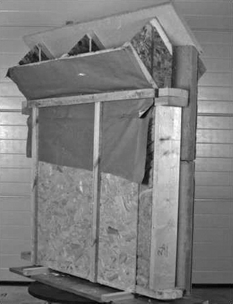
Photographs show full‐scale models of timber frame construction. The details (Figures) show the individual elements of these units. Although the timber frame provides the structural unit, the cladding can be any material that will provide the required protection from the elements and necessary security. As with all construction, attention needs to be paid to the control of airtightness. Vapour control and airtightness membranes should be lapped and taped to ensure airtightness at all points of the structure (Figure 5.11).

Figure 5.11 Tile clad timber frame: wall to upper floor detail.
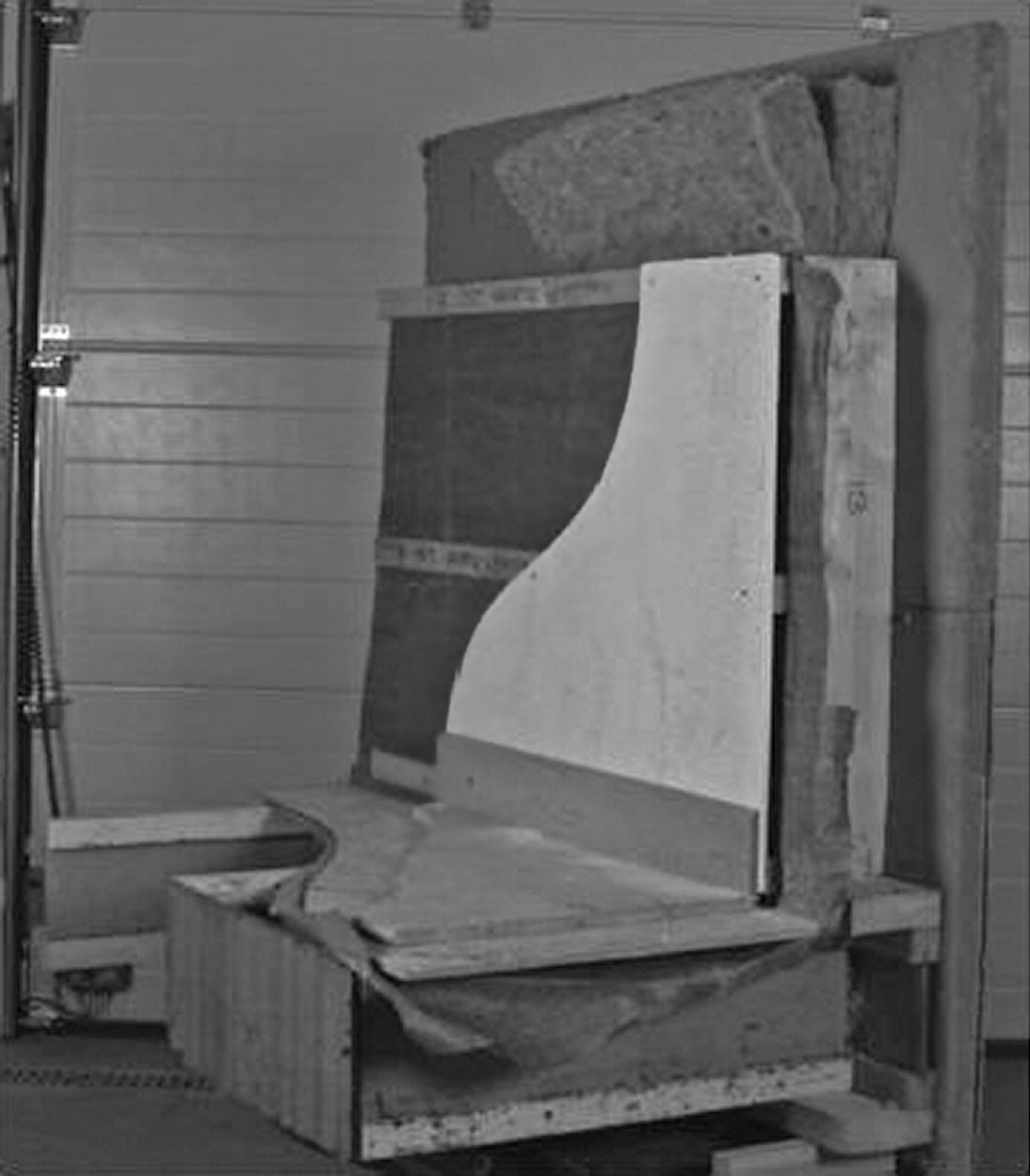
Photograph 5.4 Timber frame internal face with suspended ground floor.
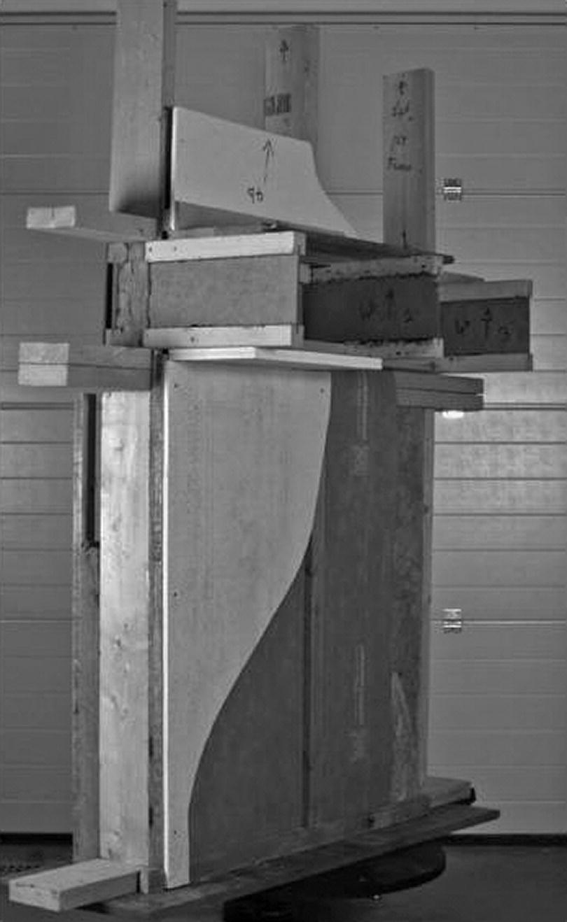
Photograph 5.5 Timber frame intermediate floor to wall junction.

Internal plasterboard linings to the timber framed walls, the soffit of the first floor and the ceiling will provide a sufficient period of fire resistance to meet the requirements for a two‐floor house. The requirement for barriers in external cavity walls to small houses applies only to the junction of a cavity and a wall separating buildings.
Prefabricated timber frames
There are three types of prefabricated timber frame systems that can be used: stick build, platform frame and balloon frame. Choice is often determined by the desired amount of work to be carried out on the building site, which has to be balanced against the cost of the timber frame. For example, some wall panels are delivered to site complete with sheathing and insulation, whereas other manufacturers provide the frame only, with the sheathing and insulation to be fixed on site.
Stick build
Using the traditional technique of stick build, the timber walls and floors are simply assembled from the individual members and components. Although not pre‐assembled, the timber members are often delivered to site pre‐cut and identified for ease of assembly. This type of construction is used to construct bespoke timber framed houses, for example, oak post and beam structures. Apart from small, self‐build and/or complicated structures, stick build is rarely used.
Platform frame
The advantage of using frames that are fabricated either on or off site complete with outer and inner finishes is speed of erection. Where a number of houses are to be built, it is possible to complete a building in a matter of days. The systems most used are either platform or storey frames. The term ‘platform’ frame equally applies to light steel frame house construction made from cold‐formed steel sections.
The platform frame system of construction employs prefabrication frames that are floor to ceiling level high, with the sole of the lower stud frame bearing on the foundation and the head of the frame supporting first floor joists, as illustrated in Figure 5.13. The first floor can then be used as a working platform from which the upper frames are set on top of the lower. The wall frames or panels may be the full width of the front and rear walls of narrow terrace houses or made in two or more panels. The first floor joists and roof provide sufficient bracing up the height and the separating wall will brace across the width of the wall. The wall frames may be prefabricated as stud frames sheathed with plywood or made complete with finishes on both sides.

Figure 5.13 Platform frame.
Platform frame is currently the most common form of timber frame construction. The panel sizes will fit easily onto standard road transport and can be easily lifted into position. Photographs show platform construction used to assemble a multi‐storey timber frame building.
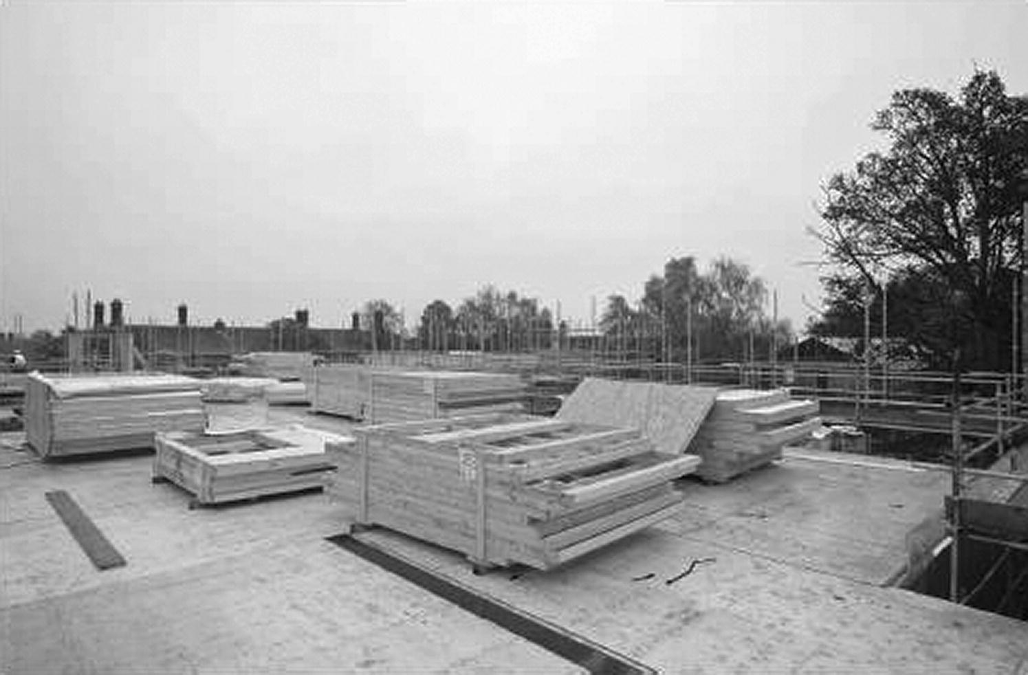
Photograph 5.9 Platform frame construction delivered to site awaiting erection.
(Source: courtesy of Shepherd Construction).

Photograph 5.10 Platform frame construction ground floor.
(Source: courtesy of Shepherd Construction).

Photograph 5.11 Vapour control membrane taped and sealed.
(Source: courtesy of Shepherd Construction).
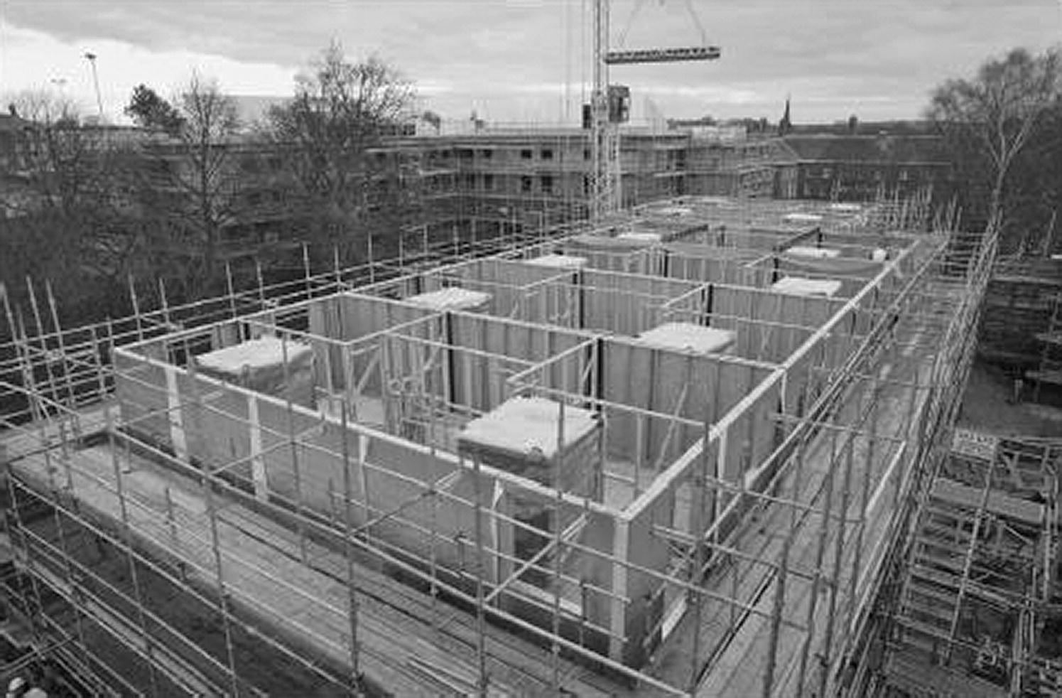
Photograph 5.12 Platform frame third storey with prefabricated bathroom pods in position.
(Source: courtesy of Shepherd Construction).

Photograph 5.13 Internal stud walls with infill panels where fixtures need to be secured.
(Source: courtesy of Shepherd Construction).
Structurally insulated panels are becoming more common and can be designed to achieve passive standards (see Photographs 5.14a–c).

Photograph 5.14 (a) Timber frame building constructed with structural insulated panel (SIP) to Passivhaus standards. (b) SIP’s panels. (c) Engineered insulated panels under construction.
Balloon frames
Storey frames (‘balloon frames’) are made the height of a storey, floor to floor, so that the top of the head of a frame is level with the top of the floor joists. A bearer fixed to the stud frame supports the joists. This arrangement provides continuity of the stud framing up the height of the wall at the expense of some loss of secure anchor of floor joists to wall. A balloon wall frame is fabricated as one continuous panel, the height of the two floors of small houses, as illustrated in Figure 5.14. The advantage of the balloon frame is speed of fabrication and erection, and the least number of joints between frames that have to be covered and weathered externally. The term ‘balloon frames’ also applies to steel frame housing (light steel, cold‐formed sections).

Figure 5.14 Balloon frame.
Functional requirements specific to timber framed buildings
Fire safety
Specifying a minimum period of fire resistance for the elements of structure restricts the premature failure of the structural stability of a building. A timber framed wall covered with plasterboard internally satisfies the requirement for houses of up to two storeys. To prevent the spread of fire between buildings, limits to the size of ‘unprotected areas’ of walls and finishes to roofs close to boundaries are set out in the Building Regulations. By reference to the boundaries of the site, the control will limit the spread of fire. Unprotected areas are those parts of external walls that may contribute to spread of fire and include glazed windows, doors and those parts of a wall that may have less than a notional fire resistance. Limits are set on the use of roof coverings that will not provide adequate protection against the spread of fire across their surface to adjacent buildings.
The passage of fire through connecting voids in timber frame construction is as significant as it is in masonry (loadbearing) construction. The connecting external and party wall cavity barriers must be sealed to prevent the passage of smoke and fire. The addition of edge seals reduces the passage of heat and improves airtightness.
Figure 5.15 shows a tee barrier used to improve the thermal insulating properties of the cavity, reduce the passage of sound and prevent the passage of fire within a specified period.
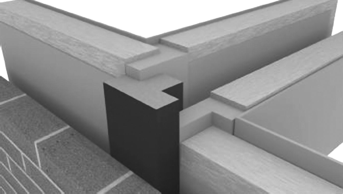
Figure 5.15 Cavity closer in timber frame
(Source: courtesy of http://www.arcbuildingsolutions.co.uk).
Resistance to the passage of heat
Timber is a comparatively good insulator. However, the sections of a timber frame do not by themselves generally afford sufficient insulation and a layer of some insulating material has to be incorporated in the construction. The layer of insulation is fixed either between the vertical studs of the frame or on the outside or inside of the framing. The disadvantage of fixing the insulation between the studs is that there may be a great deal of wasteful cutting of insulation boards to fit them between studs; and to the extent that the U‐value of the timber stud is less than that of the insulation material, there will be a small degree of thermal bridge across the studs. The advantage of fixing the insulation across the outer face of the timber frame is simplicity in fixing and the least amount of cutting. Also, the void space between the studs will augment insulation and provide space in which to conceal service pipes and cables. The disadvantage of external insulation is that the weathering finish such as weatherboarding has to be fixed to vertical battens screwed or nailed through the insulation to the studs. Unless the insulation is one of the rigid boards, it may be difficult to make a fixing for battens sufficiently firm to nail the battens to. Internal insulation is usually in the form of one of the insulation boards that combine insulation with a plasterboard finish.
Inorganic materials are most used for insulation between the studs, because there is no advantage in using the more expensive organic materials. Rolls of loosely felted fibres or compressed semi‐rigid batts or slabs of glass fibre or rockwool are used. The material in the form of rolls is hung between the studs, where it is suspended by top fixing and a loose friction fit between studs, which generally maintain the insulating material in position for the comparatively small floor heights of domestic buildings. The friction fit of semi‐rigid slabs or batts between studs is generally sufficient to maintain them, close butted, in position. For insulating lining to the outside face of studs, one of the organic insulants such as XPS or PIR provides the advantage of least thickness of insulating material for a given resistance to the transfer of heat. The more expensive organic insulants, in the form of boards, are fixed across the face of studs for ease of fixing and to save wasteful cutting. A vapour check should be fixed on to, or next to, the warm inside faces of insulants against penetration of moisture vapour. Organic insulants, such as XPS, which are substantially impervious to moisture vapour, can serve as a vapour check, particularly when rebated edge boards are used and the boards are close butted together.
Vapour check
A high level of insulation required for walls may well encourage moisture vapour held by warm inside air, particularly in bathrooms and kitchens, to find its way due to moisture vapour pressure into a timber framed wall and condense to water on the cold side of the insulation. Condensate may damage the timber frame so as a barrier to warm moist air, there should be some form of vapour check fixed on the warm side of the insulation. Closed cell insulating materials such as XPS, in the form of rigid boards, are impermeable to moisture vapour and will act as a vapour check. The boards should either be closely butted together or supplied with rebated or tongued and grooved edges so that they fit tightly and serve as an efficient vapour check.
Where insulation materials that are pervious to moisture vapour, such as mineral fibre, are used for insulation between studs, a vapour check of polythene sheet must be fixed across the warm side of the insulation. The polythene sheet should be lapped at joints and continued up to unite with any vapour check in the roof and should, as far as practical, not be punctured by service pipes.
The vapour check is now also being incorporated as an airtightness control membrane (see Photographs ). To ensure airtightness and vapour control, timber framed buildings are now externally wrapped and sealed internally.
To prevent overheating of electrical cables that run through insulation, the cables should be de‐rated by a factor of 0.75 by using larger cables than specified, which will generate less heat. So that cables are not run through insulation, it is wise to fix the inside dry lining to timber frames that are filled with insulation onto timber battens nailed across the frame, so that there is a void space in which cables can be safely run.
Resistance to the passage of sound
The small mass of a timber framed wall affords little resistance to airborne sound, but does not readily conduct impact sound. The thermal insulation necessary for the conservation of heat will give some reduction in airborne sound and the use of a brick or block outer leaf will appreciably reduce the intrusion of airborne sound from outside the property. Where sound pollution is a problem, acoustic plasterboard may be used to reduce sound transmission. The acoustic plasterboard is designed to reduce sound transmission and is fixed to studwork in a similar manner to plasterboard. To ensure that the acoustic board is effective, the joints should be staggered and sealed, holes should not be cut into the board and services should not pass through the board.
5.5 High‐rise structural timber frames
Traditionally it has been common to restrict framed timber buildings to relatively modest height, typically low‐rise (one to two storeys) and mid‐rise (three to five storeys). With advances in manufacturing techniques, a move to performance based regulations, and increased awareness of the environmental impact of buildings, interest has turned to the construction of tall buildings using structural timber frames. New timber technologies, such as engineered timber, have helped make it possible to build taller in timber. Buildings are now being erected that are higher then six storeys, with some extending to ten or more. These are classified as high‐rise timber buildings. While such technologies offer fast and low‐carbon construction, there are technical issues that require further research and development, and perceptions in relation to safety that need to be addressed.
Although there are perceived concerns about fire safety and structural safety, the small number of pioneering tall timber framed buildings have proved that it is possible to build tall in timber and maintain stability and safety. High‐rise timber frames rely on heavy (massive) timber members to create the frame. The timber used is usually large‐section engineered timber to form the columns and beams of the building superstructure. Solid sawn timber sections may also be also used for the structural frame. These large sections perform differently compared to light timber sections in a fire and provide inherent fire resistance. The charring to the surface in a fire protects the element and helps to maintain the structural integrity of the structural frame in a fire. Similar to steel and concrete, framed construction, the integrity of the building in a fire is determined by the interaction of many components and their fixings, together with the provision of fire and smoke stops and fire resistant finishes. Ideally, the beauty of the wood needs to be appreciated, not concealed behind fire resistant plasterboard. Sprinklers may also be required as part of the fire engineering strategy for the whole building. This has to be demonstrated at the design and engineering phase, to ensure compliance with prevailing legislation.
A variety of approaches are being used, ranging from the use of structural timber frame and a concrete lift/service core, to provide lateral stability to structural timber frame construction and a cross‐laminated timber (CLT) lift/service core. Other approaches rely on framed wall construction that has evolved from the low‐rise timber framed housing techniques. This is an area of construction in which the boundaries of height and construction techniques are very much at an early stage, as engineers and manufacturers continue to explore possibilities.