
6
Structural Steel Frames
Structural steel frames are a popular choice for tall buildings. The advantages of the structural steel frame are the speed of erection of the ready‐prepared steel members and the accuracy of setting out and connections that is a tradition in engineering works. Accurate placing of steel members, with small tolerances, facilitates the fixing of cladding materials and curtain walls. With the use of sprayed‐on or dry lining materials to encase steel members to provide protection against damage by fire, a structural steel frame may be more economical than a reinforced concrete structural frame, because of speed of erection and economy in material and construction labour costs. Steel components can also be reclaimed, reused and recycled when the building is deconstructed at the end of its life.
6.1 Functional requirements
The functional requirements of a structural frame are:
- Strength and stability
- Durability and freedom from maintenance
- Fire safety
Strength and stability
The requirements from the Building Regulations are that buildings be constructed so that the loadbearing elements, foundations, walls, floors and roofs have adequate strength and stability to support the dead loads of the construction and anticipated imposed loads on roofs, floors and walls, without such undue deflection or deformation as might adversely affect the strength and stability of parts or the whole of the building. The strength of the loadbearing elements of the structure is assumed either from knowledge of the behaviour of similar traditional elements, such as walls and floors under load, or by calculations of the behaviour of parts or the whole of a structure under load, based on data from experimental tests, with various factors of safety to make allowance for unforeseen construction or design errors. The strength of individual elements of a structure may be reasonably accurately assessed by taking account of tests on materials and making allowance for variations of strength in both natural and man‐made materials.
The strength of combinations of elements such as columns and beams depends on the rigidity of the connection and the consequent interaction of the elements. Simple calculations, based on test results, of the likely behaviour of the joined elements or a more complex calculation of the behaviour of the parts of the whole of the structure, can be made. Various factors of safety are included in calculations to allow for unforeseen circumstances. Calculations of structural strength and stability provide a mathematical justification for an assumption of a minimum strength and stability of structures in use.
Imposed loads are those loads that it is assumed the building or structure is designed to support, taking account of the expected occupation or use of the building or structure. Assumptions are made of the likely maximum loads that the floors of a category of building may be expected to support. The load of the occupants and their furniture on the floors of residential buildings will generally be less than that of goods stored on a warehouse floor.
The loads imposed on roofs by snow are determined by taking account of expected snow loads in the geographical location of the building. Loads imposed on walls and roofs by wind (wind loads) are determined by reference to the situation of the building on a map of the UK on which basic wind speeds have been plotted. These basic wind speeds are the maximum gust speeds averaged over 3 second periods, which are likely to be exceeded on average only once in 50 years. In the calculation of the wind pressure on buildings, a correction factor is used to take account of the shelter from wind afforded by obstructions and ground roughness.
The stability of a building depends initially on a reasonably firm, stable foundation. The stability of a structure depends on the strength of the materials of the loadbearing elements in supporting, without undue deflection or deformation, both concentric and eccentric loads on vertical elements and the ability of the structure to resist lateral pressure of wind on walls and roofs.
The very considerable deadweight of walls of traditional masonry or brick construction is generally sufficient, by itself, to support concentric and eccentric loads and the lateral pressure of wind. Generally, the deadweight of skeleton‐framed multi‐storey buildings is not, by itself, capable of resisting lateral wind pressure without undue deflection and deformation. Some form of bracing is required to enhance the stability of skeleton‐framed buildings. Unlike the joints in a reinforced concrete structural frame, the normal joints between vertical and horizontal members of a structural steel frame do not provide much stiffness in resisting lateral wind pressure.
Disproportionate collapse
A requirement from the Building Regulations is that a building shall be constructed so that, in the event of an accident, the building will not suffer collapse to an extent disproportionate to the cause. This requirement applies only to a building having five or more storeys (each basement level being counted as one storey), excluding a storey within the roof space, where the slope of the roof does not exceed 70° to the horizontal.
Durability and freedom from maintenance
The members of a structural steel frame are usually inside the wall fabric of buildings, so that in usual circumstances the steel is in a comparatively dry atmosphere, which is unlikely to cause progressive, destructive corrosion of steel. Structural steel will, therefore, provide reasonable durability for the expected life of the majority of buildings and require no maintenance. Where the structural steel frame is partially or wholly built into the enclosing masonry or brick walls, the external wall thickness is generally adequate to prevent such penetration of moisture as is likely to cause corrosion of steel. Where there is some likelihood of penetration of moisture to the structural steel, it is usual practice to provide protection by the application of paint or bitumen coatings or the application of a damp‐proof layer. Where it is anticipated that moisture may cause corrosion of the steel, either externally or from a moisture‐laden interior, weathering steels, which are much less subject to corrosion, are used.
Fire safety
The application of the Regulations, as set out in the practical guidance given in Approved Document B, is directed to the safe escape of people from buildings in case of fire, rather than the protection of the building and its contents. Insurance companies that provide cover against the risks of damage to the building and contents by fire may require additional fire protection such as sprinklers.
Internal fire spread (structures)
The requirement from the Regulations relevant to structure is to limit internal fire spread (structure). As a measure of ability to withstand the effects of fire, the elements of a structure are given notional fire resistance times, in minutes, based on tests. Elements are tested for their ability to withstand the effects of fire in relation to:
- Resistance to collapse (loadbearing capacity), which applies to loadbearing elements
- Resistance to fire penetration (integrity), which applies to fire separating elements
- Resistance to the transfer of excessive heat (insulation), which applies to fire separating elements
The notional fire‐resisting times, which depend on the size, height, number of basements and use of buildings, are chosen as being sufficient for the escape of occupants in the event of fire. The requirements for the fire resistance of elements of a structure do not apply to:
- A structure that supports only a roof unless:
- The roof acts as a floor (e.g. car parking), or as a means of escape
- The structure is essential for the stability of an external wall, which needs to have fire resistance
- The lowest floor of the building
6.2 Methods of design
There are a number of established approaches to the method of design of structural steel frames, as described later. It is also possible for engineers and designers to use some simple ‘rules of thumb’ to quickly establish the depth of, for example, a steel beam for a specific span to give an indication as to the depth of the structure.
Rules of thumb
Simple ‘rules of thumb’ can be used to quickly establish an approximate size for steel columns and beams given typical loading conditions. This may be useful in the very early design stages, when a number of options are being explored to quickly establish what may or may not be feasible. This method has largely been superseded by BIM and computer software programs, although rules of thumb can also be used to check the validity of results from software programs. For steel I beams, the quick way to size a steel beam is to divide the span by 20. For a 12 m clear span, the beam would be approximately 600 mm deep. The column size will depend on the floor area it is supporting and the imposed loads on the floor area. Calculations will be required to coordinate the dimensions of beams and columns to ensure an efficient design that facilitates ease of construction.
Permissible stress design method
With the introduction of steel as a structural material in the late 19th and early years of the 20th centuries, the permissible stress method of design was accepted as a basis for the calculation of the sizes of structural members. Having established and agreed a yield stress for mild steel, the permissible tensile stress was taken as the yield stress divided by a factor of safety, to allow for unforeseen overloading, defective workmanship and variations in steel. The yield stress in steel is that stress at which the steel no longer behaves elastically and suffers irrecoverable elongation, as shown in Figure 6.1, which is a typical stress/strain curve for mild steel.
Figure 6.1 Stress/strain curve for mild steel.
Yield point: the point at which the material under stress no longer behaves elastically; point at which permanent deformation (plastic deformation or flow) begins.
Elastic limit: the maximum stress or force per unit area that can be applied to a material without causing permanent deformation; the highest point on the graph before the straight line changes to a curve.
Tensile strength: the maximum stress that a material can sustain before tearing or failing while the material is being stretched.
Fracture: the point at which the material breaks.
The loads to be carried by a structural steel frame are dead, imposed and wind loads. Dead loads comprise the weight of the structure including walls, floors, roof and all permanent fixtures. Imposed loads include all movable items that are stored on or usually supported by floors, such as goods, people, furniture and movable equipment. Wind loads are those applied by wind pressure or suction on the building. Dead loads can be accurately calculated. Imposed loads are assumed from the common use of the building to give reasonable maximum loads that are likely to occur. Wind loads are derived from the maximum wind speeds.
Having determined the combination of loads that are likely to cause the worst working conditions the structure is to support, the forces acting on the structural members are calculated by the elastic method of analysis to predict the maximum elastic working stresses in the members of the structural frame. Beam sections are then selected so that the maximum predicted stress does not exceed the permissible stress. In this calculation, a factor of safety is applied to the stress in the material of the structural frame. The permissible compressive stress depends on whether a column fails due to buckling or yielding and is determined from the slenderness ratio of the column, Young’s modulus and the yield stress divided by a factor of safety. The permissible stress method of design provides a safe and reasonably economic method of design for simply connected frames and is the most commonly used method of design for structural steel frames.
A simply connected frame is a frame in which the beams are assumed to be simply supported by columns, to the extent that while the columns support beam ends, the beam is not fixed to the column and in consequence when the beam bends (deflects) under load, bending is not restrained by the column. Where a beam bears on a shelf angle fixed to a column and the top of the beam is fixed to the column by means of a small top cleat designed to maintain the beam in a vertical position, it is reasonable to assume that the beam is simply supported and will largely behave as if it had a pin‐jointed connection to the column.
Collapse or load factor method of design
Where beams are rigidly fixed to columns and where the horizontal or near‐horizontal members of a frame, such as the portal frame, are rigidly fixed to posts or columns, then beams do not suffer the same bending under load that they would if simply supported by columns or posts. The effect of the rigid connection of beam ends to columns is to restrain simple bending, as illustrated in Figure 6.2. The fixed end beam bends in two directions, upwards near fixed ends and downwards at the centre. The upward bending is termed ‘negative bending’ and the downward bending termed ‘positive bending’. It will be seen that bending at the ends of the beam is prevented by the rigid connections that take some of the stress due to loading and transfer it to the supporting columns. Just as the rigid connection of beam to column causes negative or upward bending of the beam at the ends, so a comparable, but smaller, deformation of the column will occur.
Figure 6.2 Comparison of pin‐jointed and fixed end beams.
Using the elastic method of analysis to determine working stress in a fixed end beam, to select a beam section adequate for the permissible stress, the design method produces a section greater than is needed to provide a reasonable factor of safety against collapse, because in practice the permissible stress is not reached and in consequence the beam could safely support a greater load.
The collapse or load factor method of design seeks to provide a load factor, that is, a safety factor, against collapse applied to particular types of structural frame for economy in the use of materials, by using the load factor which is applied to the loads instead of stress in materials. The load factor method was developed principally for use in the design of reinforced concrete and welded connection steel frames with rigid connections as an alternative to the permissible stress method, as a means to economy in the selection of structural sections. In the use of the load factor method of design, plastic analysis is used. In this method of analysis of the forces acting in members, it is presumed that extreme fibre stress will reach or exceed yield stress and the fibres behave plastically. This is a valid assumption as, in practice, the fibres of the whole section play a part in sustaining stress, and under working loads extreme fibre stress would not reach yield point.
Limit state method of design
The purpose of structural analysis is to predict the conditions applicable to a structure that would cause it to become either unserviceable in use or unable to support loads to the extent that members might fail.
In the permissible stress method, a limit is set on the predicted working stress in the members of the frame, by the use of a factor of safety applied to the predicted yield stress of the materials used. In the load factor method of design, a limit is set on the working loads to ensure that they do not exceed a limit determined by the application of a factor of safety to the loads that would cause collapse of the structure. The limit state method of design seeks to determine the limiting states of both materials and loads that would cause a particular structure to become unserviceable in use or unsafe due to excessive load. The limiting conditions that are considered are serviceability during the useful life of the building and the ultimate limit state of strength.
Serviceability limit states set limits on the behaviour of the structure to limit excessive deflection, excessive vibration and irreparable damage due to material fatigue or corrosion that would otherwise make the building unserviceable in use. Ultimate limit states of strength set limits to strength in resisting yielding, rupture, buckling and transformation into a mechanism, and stability against overturning and fracture due to fatigue or low‐temperature brittleness.
During use, the limit state method of design sets characteristic loads and characteristic strengths, which are those loads and strengths that have an acceptable chance of not being exceeded during the life of the building. To take account of the variability of loads and strength of materials in actual use, a number of partial safety factors may be applied to the characteristic loads and strengths to determine safe working loads and strengths.
The limit state method of design has not been accepted wholeheartedly by structural engineers because, they say, it is academic, highly mathematical, increases design time and does not lead to economic structures. There is often little reward in employing other than the permissible stress method of design for the majority of buildings, so that the use of the limit state method is confined in the main to larger and more complex structures where the additional design time is justified by more adventurous and economic design.
6.3 Steel sections
Mild steel is the material generally used for constructional steelwork. It is produced in several basic strength grades of which those designated as 43, 50 and 55 are most commonly used. The strength grades 43, 50 and 55 indicate minimum ultimate tensile strengths of 430, 500 and 550 N/mm2, respectively. Each strength grade has several sub‐grades indicated by a letter between A and E; the grades that are normally available are 43A, 43B, 43C, 43D, 43E, 50A, 50B, 50C, 50D and 55C. In each strength grade, the sub‐grades have similar ultimate tensile strengths, and as the sub‐grades change from A to E, the specification becomes more stringent, the chemical composition changes and the notch ductility improves. The improvement in notch ductility (reduction in brittleness), particularly at low temperatures, assists in the design of welded connections and reduces the risk of brittle and fatigue failure, which is of particular concern in structures subject to low temperatures.
Properties of mild steel
Strength
Steel is strong in both tension and compression with permitted working stresses of 165, 230 and 280 N/mm2 for grades 43, 50 and 55, respectively. The strength‐to‐weight ratio of mild steel is good, so that mild steel is able to sustain heavy loads with comparatively small self‐weight.
Elasticity
Under stress induced by loads, a structural material will stretch or contract by elastic deformation and return to its former state once the load is removed. The ratio of stress to strain, which is known as Young’s modulus (the modulus of elasticity), gives an indication of the resistance of the material to elastic deformation. If the modulus of elasticity is high, the deformation under stress will be low. Steel has a high modulus of elasticity, 200 kN/mm2, and is therefore a comparatively stiff material, which will suffer less elastic deformation than aluminium, which has a modulus of elasticity of 69 kN/mm2. Under stress induced by loads, beams bend or deflect, and in practice this deflection under load is limited to avoid cracking of materials fixed to beams. The sectional area of a mild steel beam can be less than that of other structural materials for a given load, span and limit of deflection.
Ductility
Mild steel is a ductile material which is not brittle and can suffer strain beyond the elastic limit through what is known as plastic flow, which transfers stress to surrounding material so that at no point will stress failure in the material be reached. Because of the ductility of steel, the plastic method of analysis can be used for structures with rigid connections, which makes allowance for transfer of stress by plastic flow and so results in a section less than would be determined by the elastic method of analysis, which does not make allowance for the ductility of steel.
Resistance to corrosion
Corrosion of steel occurs as a chemical reaction between iron, water and oxygen to form hydrated iron oxide, commonly known as rust. Because rust is open grained and porous, a continuing reaction will cause progressive corrosion of steel. The chemical reaction that starts the process of corrosion of iron is affected by an electrical process through electrons liberated in the reaction, whereby small currents flow from the area of corrosion to unaffected areas and so spread the process of corrosion. In addition, pollutants in air accelerate corrosion as sulphur dioxides from industrial atmospheres and salt in marine atmospheres increase the electrical conductivity of water and so encourage corrosion. The continuing process of corrosion may eventually, over the course of several years, affect the strength of steel. Mild steel should therefore be given protection against corrosion in atmospheres likely to cause corrosion.
Fire resistance
Although steel is non‐combustible and does not contribute to fire, it may lose strength when its temperature reaches a critical point in a fire in a building. Therefore some form of protection against fire is required.
Weathering steels (COR‐TEN)
The addition of small quantities of certain elements modifies the structure of the rust layer that forms. The alloys encourage the formation of a dense, fine‐grained rust film and also react chemically with sulphur in atmospheres to form insoluble basic sulphate salts that block the pores on the film and so prevent further rusting. The thin, tightly adherent film that forms on this low alloy steel is of such low permeability that the rate of corrosion is reduced almost to zero. The film forms a patina of a deep brown colour on the surface of steel, giving a rust‐like appearance. The low‐permeability rust film forms under normal wet/dry cyclical conditions. In conditions approaching constant wetness and in conditions exposed to severe marine or salt spray conditions, the rust film may remain porous and not prevent further corrosion. Weathering steels are produced under brand names, the most well known being ‘COR‐TEN’, which is a particular favourite of artists, architects and engineers for its appearance and durability. Typical uses include large urban art installations, exposed frames and surfaces of buildings and bridges. Weathering steels require special welding techniques to ensure the weld points weather at the same rate as the steel alloy. Care is also required to ensure that the initial runoff from the steel does not discolour and stain adjacent materials as it weathers.
Standard rolled steel sections
The steel sections most used in structural steelwork are standard hot‐rolled steel universal beams and columns together with a range of tees, channels and angles illustrated in Figure 6.3. Universal beams and columns are produced in a range of standard sizes and weights designated by serial sizes. Within each serial size, the inside dimensions between flanges and flange edge and web remain constant, and the overall dimensions and weights vary, as illustrated in Figure 6.4. This grouping of sections in serial sizes is convenient for production within a range of rolling sizes and for the selection of a suitable size and weight by the designer. The deep web to flange dimensions of beams and the near similar flange to web dimensions of columns are chosen to suit the functions of the structural elements. Because of the close similarity of the width of the flange to the web of column sections, they are sometimes known as ‘broad flange sections’.

Figure 6.3 Hot‐rolled structural steel sections.
Figure 6.4 Universal columns.
A range of comparatively small section ‘joists’ are also available, which have shallowly tapered flanges and are produced for use as beams for small to medium spans. The series of structural T’s is produced from cuts that are half the web depth of standard universal beams and columns. The range of standard hot‐rolled structural steel angles and channels has tapered flanges. The standard rolled steel sections are usually supplied in strength grade 43A material with strength grades 50 and 55 available for all sections at an additional cost per tonne. All of the standard sections are available in Cor‐Ten B weathering steel.
Castella beam
An open web beam can be fabricated by cutting the web of a standard section mild steel beam along a castellated line, as illustrated in Figure 6.5. The two cut sections of the beam are then welded together to form an open web, castellated beam, which is one and a half times the depth of the beam from which it was formed. Because of the increase in depth, the castella beam will suffer less deflection (bending) under light loads. The castella beam is no stronger than the beam from which it was cut but will suffer less deflection under load. The increase in cost due to fabrication and the reduction in weight of the beam as compared to a solid web beam of the same depth and section justify the use of these beams for long‐span, lightly loaded beams particularly for roofs. The voids in the web of these beams are convenient for housing runs of electrical and heating services.
Figure 6.5 Castella beam.
Steel tubes
A range of seamless and welded seam steel tubes is manufactured for use as columns, struts and ties. The use of these tubes as columns is limited by the difficulty of making beam connections to a round section column. These round sections are the most efficient and compact structural sections available and are extensively used in the fabrication of lattice girders, columns, frames, roof decks and trusses for economy, appearance and comparative freedom from dust traps. Connections are generally made by scribing the ends of the tube to fit around the round sections to which they are welded. For long‐span members such as roof trusses, bolted plate connections are made at mid‐span for convenience in transporting and erecting long‐span members in sections.
Hollow rectangular and square sections
Hollow rectangular and square steel sections are made from hollow round sections of steel tube, which are heated until they are sufficiently malleable to be deformed. The heated tubes are passed through a series of rollers, which progressively change the shape of the tube to square or rectangular sections with rounded edges, as illustrated in Figure 6.6. To provide different wall thicknesses, the heated tube can be gradually stretched. The advantage of these sections is that they are ideal for use as columns as the material is uniformly disposed around the long axis, and the square or rectangular section facilitates beam connections.
Figure 6.6 Hollow steel sections.
Hollow square and rectangular sections are much used as the members of lattice roof trusses and lightly loaded framed structures with the square sections for columns and the rectangular sections as beams. The economy in material and the neat appearance of the sections, which with welded connections have a more elegant appearance than angle connections, recommend their use. These sections are also much used in the fabrication of railings, balustrades, gates and fences with welded connections for the neat, robust appearance of the material. Prefabricated sections can be hot dip galvanised to inhibit rusting prior to painting.
Cold roll‐formed steel sections
Cold roll‐formed structural steel sections are made from hot‐rolled steel strip, which is passed through a series of rollers. Each pair of rollers progressively takes part in gradually shaping the strip to the required shape. As the strip is cold formed, it has to be passed through a series of rollers to avoid the thin material being torn or sheared in the forming process, which produces sections with slightly rounded angles to this end. There is no theoretical limit to the length of steel strip that can be formed. The thickness of steel strip commonly used is from 0.3 to 0.8 mm and the width of strip up to about 1 m. A very wide range of sections is possible with cold‐rolled forming, some of which are illustrated in Figure 6.7.
Figure 6.7 Cold roll‐formed sections.
The advantage of cold‐rolled forming is that any shape can be produced to the exact dimensions to suit a particular use or design. Figure 6.8 is an illustration of cold‐formed sections, spot welded back to back to form structural steel beam sections, and sections welded together to form box form column sections. Connections of cold‐formed sections are made by welding self‐tapping screws or bolts to plate cleats welded to one section. Because of the comparatively thin material from which the sections are formed, it is necessary to use some coating that will inhibit corrosion and some form of casing as protection against early damage by fire where regulations so require. Cold‐formed steel sections are extensively used in the manufacture of roof trusses and lattice beams and frames. The fabricated sections are protected with a galvanised coating where practical. Cold‐formed, pressed steel sections are much used for floor and roof decking for the floors of framed buildings and also for metal doors, frames and metal trim such as skirtings.
Figure 6.8 Cold roll‐formed sections welded together.
Steel frame wall construction for domestic houses
Although steel is traditionally associated with large commercial and industrial buildings, light gauge steel (cold‐formed steel sections) is used in domestic house construction. The sections of steel are used in a similar way to timber sections to form a structural frame. Because the steel frame is a good conductor of heat, it is important that the insulation is not placed between the metal frame, as this would create thermal bridges. Instead, the insulation should be applied to the inside of the cavity. Rolled steel sections can be assembled using either stick, panel or balloon construction.
When using stick construction, the individual members are delivered to site pre‐cut and pre‐punched for holes to be cut and self‐tapping screws to be used. Advantages of stick‐build construction are that small modifications and adjustments can be made on site to accommodate site tolerances and very minor design changes. Structural members can be packed and transported in small, tightly packed, loads. However, stick build construction is labour intensive and is not widely used in the UK. Panel and balloon frame construction tend to be more attractive alternatives.
Panel construction has the advantage that the wall subframes, panels, floors and roof trusses are prefabricated under carefully controlled factory conditions and then delivered to site as ready assembled elements. The subframes and panels are connected on site using bolts or self‐tapping screws. Quality control is achieved via factory production, and the accuracy of the components and panels make them easy and quick to assemble on site.
In balloon construction the panels are much larger, comprising floor to roof elements, although the components are manufactured in much the same as panel frame construction.
6.4 Structural steel frames
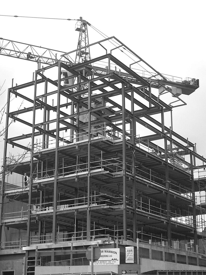
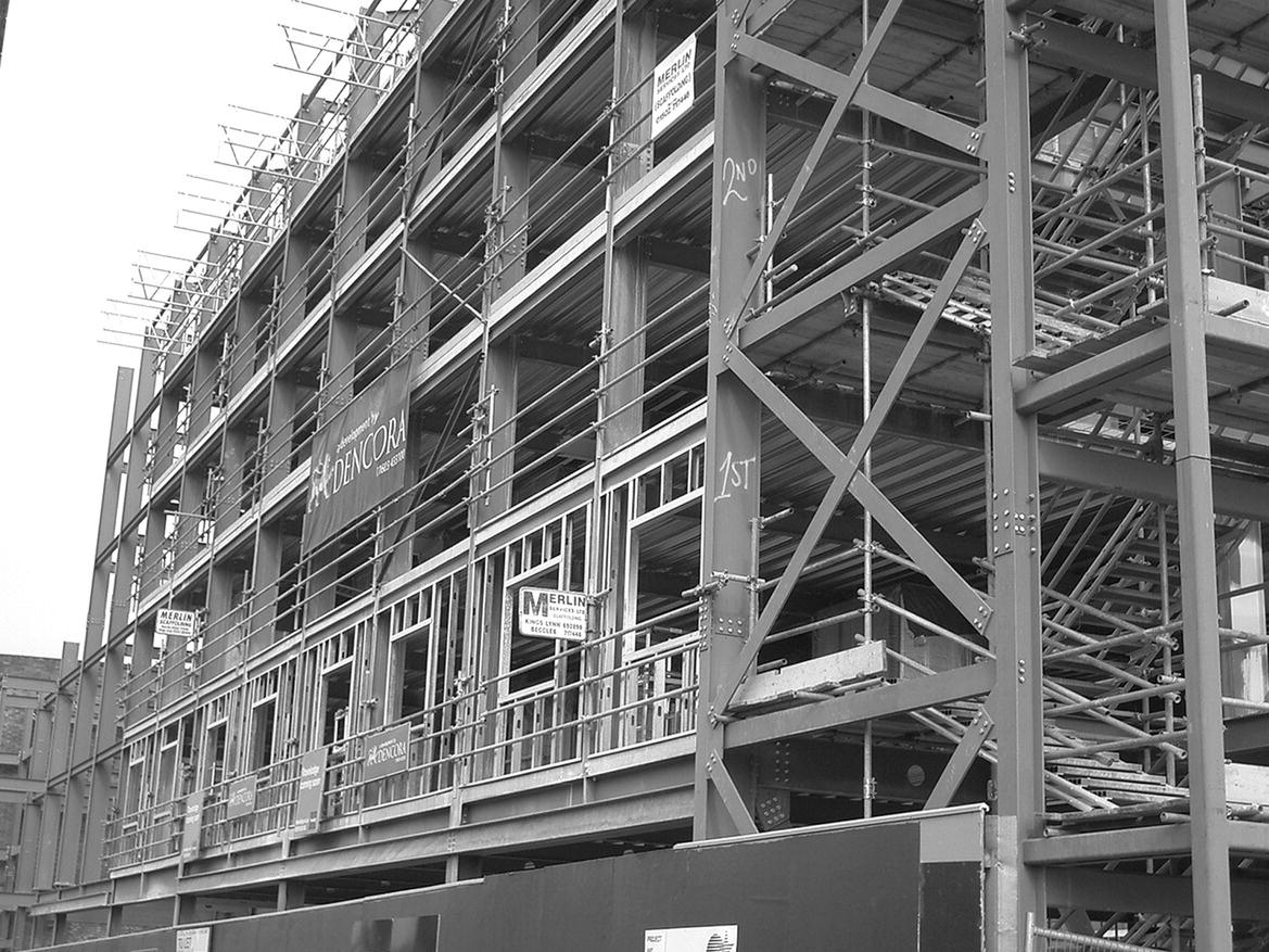
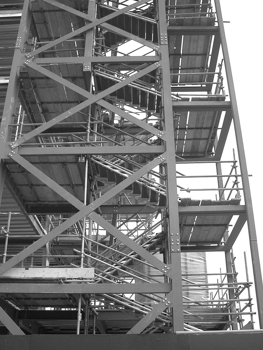
The earliest structural steel frame was erected in Chicago in 1883 for the Home Insurance building. A skeleton of steel columns and beams carried the whole of the load of floors, and solid masonry or brick walls were used for weather protection and appearance. Since then the steel frame has been one of the principal methods of constructing multi‐storey buildings (Photograph 6.1).
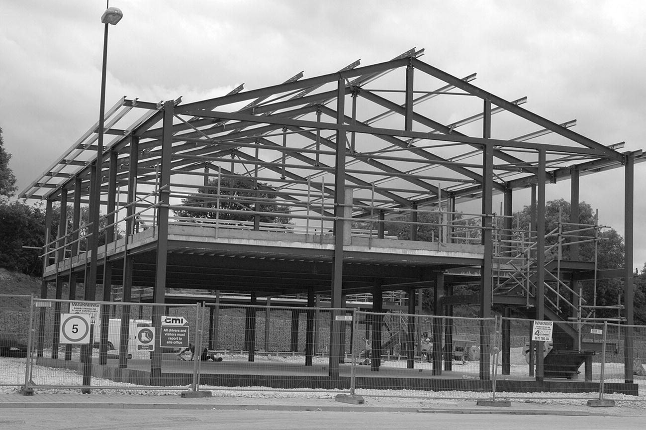
Photograph 6.1 Steel frame office building under construction.
Skeleton frame
The conventional steel frame is constructed with hot‐rolled section beams and columns in the form of a skeleton designed to support the whole of the imposed and dead loads of floors, external walling or cladding and wind pressure (Photograph 6.2). The arrangement of the columns is determined by the floor plans, horizontal and vertical circulation spaces and the requirements for natural light to penetrate the interior of the building. Figure 6.9 is an illustration of a typical rectangular grid skeleton steel frame. In general, the most economic arrangement of columns is on a regular rectangular grid with columns spaced at 3.0–4.0 m apart, parallel to the span of floors which bear on floor beams spanning up to 7.5 m with floors designed to span one way between main beams. This arrangement provides the smallest economic thickness of floor slab and least depth of floor beams, and therefore least height of building for a given clear height at each floor level.
Photograph 6.2 Skeleton frame with concrete lift shaft core.
Figure 6.9 Rectangular grid steel frame.
Figure 6.10 is an illustration of a typical small skeleton steel frame designed to support one‐way span floors on main beams and beams to support solid walls at each floor level on the external faces of the building. This rectangular grid can be extended in both directions to provide the required floor area.

Figure 6.10 Structural steel skeleton frame.
Where comparatively closely spaced columns may obstruct internal floor space, a larger rectangular or square grid of columns is used. The columns support main beams, which in turn support secondary beams spaced at up to 4.5 m apart to carry one‐way span floor slabs, as illustrated in Figure 6.11 and Photograph 6.3. This arrangement allows for the least span and thickness of floor slab and the least weight of construction.
Figure 6.11 Wide‐span column grid.
Photograph 6.3 Skeleton frame with wide‐span column grid.
A disadvantage of this layout is that the increased span of main beams requires an increase in their depths so that they will project below the underside of the secondary beams. Heating, ventilating and electrical services, which are suspended and run below the main beams, are usually hidden above a suspended ceiling. The consequence is that the requirement for comparatively unobstructed floor space causes an increase in the overall height of a building because of the increase in depth of floor from floor finish to suspended ceiling at each floor level. Where there is a requirement for a large floor area unobstructed by columns, either a deep long‐span solid web beam, a deep lattice girder or Vierendeel girders are used.
The advantage of using deep lattice girders or Vierendeel girders is that they may be designed so that their depth occupies the height of a floor and does not, therefore, increase the overall height of construction. The Vierendeel girder illustrated in Figure 6.12 is fabricated from mild steel plates, angles, channels and beam sections, which are cut and welded together to form an open web beam. The advantage of the open web form is that it can accommodate both windows externally and door openings internally, unlike the diagonals of a lattice girder of the same depth. The solid parts of the web of this girder are located under the columns they are designed to support. The specialist fabrication of this girder together with the cost of transporting and hoisting into position involves considerable cost.

Figure 6.12 Vierendeel girder.
The conventional structural steel frame comprises continuous columns which support short lengths of beam that are supported on shelf angles bolted to the columns. Where there is a requirement, for example, for the structural frame to overhang a pavement, the frame has to be cantilevered out, as illustrated in Figure 6.13. To support the columns on the external face of the cantilever, it is necessary to use shorter lengths of the main external column carried on continuous cantilever beams. The continuous cantilever beam is carried back and connected to an internal column. To support the cantilever, a short length of column is connected under the cantilever beam to which web stiffeners are welded to reinforce the beam against web buckling.

Figure 6.13 Continuous beam to form cantilever.
Parallel beam structural steel frame
The parallel beam structural steel frame uses double main or spine beams fixed on each side of internal columns to support secondary rib beams that support the floor. The principal advantage of this form of structure is improved flexibility for the services, which can be located in both directions within the grid between the spine beams in one direction and the rib beams in the other. The advantage of using two parallel main spine beams is simplicity of connections to columns and the use of continuous long lengths of beam independent of column grid, which reduces fabrication and erection complexities and the overall weight of steel.
The most economical arrangement of the frame is a rectangular grid with the more lightly loaded rib beams spanning the greater distance between the more heavily loaded spine or main beams. Where long‐span ribs are used, for reasons of convenience in internal layout or for convenience in running services or both, a square grid may be most suitable. The square grid illustrated in Figure 6.14 uses double spine or main beams to internal columns with pairs of rib beams fixed to each side of columns with profiled steel decking and composite construction structural concrete topping fixed across the top of the rib beams. The spine beams are site bolted to end plates welded to short lengths of channel section steel that are shop welded to the columns. At the perimeter of the building, a single spine beam is bolted to the end plate of channel sections welded to the column.

Figure 6.14 Parallel beam structural steel frame.
The parallel beam structural frame may be used, with standard I‐section beams and columns or with hollow rectangular section columns and light section rolled steel sections or cold‐formed strip steel beams and ribs, for smaller buildings supporting moderate floor loads in which there is a need for provision for the full range of electric and electronic cables and air conditioning. Although the number of steel sections used for each grid of the framework in this system is greater than that needed for the conventional steel frame, there is generally some appreciable saving in the total weight and, therefore, the cost of the frame, and appreciable saving in the erection time due to the simplicity of connections. The overall depth of the structural floor is greater than that of a similar conventional structural steel frame. Services may be housed within the structural depth, rather than being slung below the structural floor of a conventional frame above a suspended ceiling, which can help to reduce the overall height of the building for a given clear height between the finished floor and ceiling level.
Pin‐jointed structural steel frames
The shortage of materials and skilled craftsmen that followed the Second World War encouraged local authorities in the UK to develop systems of building employing standardised components that culminated in the Consortium of Local Authorities Special Programme (CLASP) system of building. The early development was carried out by the Hertfordshire Country Council in 1945, in order to fulfil their school building programme. A system of prefabricated building components based on a square grid was developed, to utilise light engineering prefabrication techniques, aimed at economy by mass production and the reduction of site labour. Some 10 years later, the Nottinghamshire County Council, faced with a similar problem and in addition the problem of designing a structure to accommodate subsidence due to mining operations, developed a system of building based on a pin‐jointed steel frame, with spring loaded diagonal braces, and prefabricated components.
In order to gain the benefits of economy in mass production of component parts, the Nottinghamshire County Council joined with other local authorities to form CLASP, which was able to order, well in advance, considerable quantities of standard components at reasonable cost. The CLASP system of building has since been used for schools, offices, housing and industrial buildings of up to four storeys. The system retained the pin‐jointed frame, originally designed for mining subsidence areas, as being the cheapest light structural steel frame. The CLASP system is remarkable in that it was designed by architects for architects and allows a degree of freedom of design, within standard modules and using a variety of standard components, which no other system of prefabrication has yet to achieve. The CLASP building system is illustrated in Figure 6.15.

Figure 6.15 Pin‐jointed steel frame.
Wind bracing
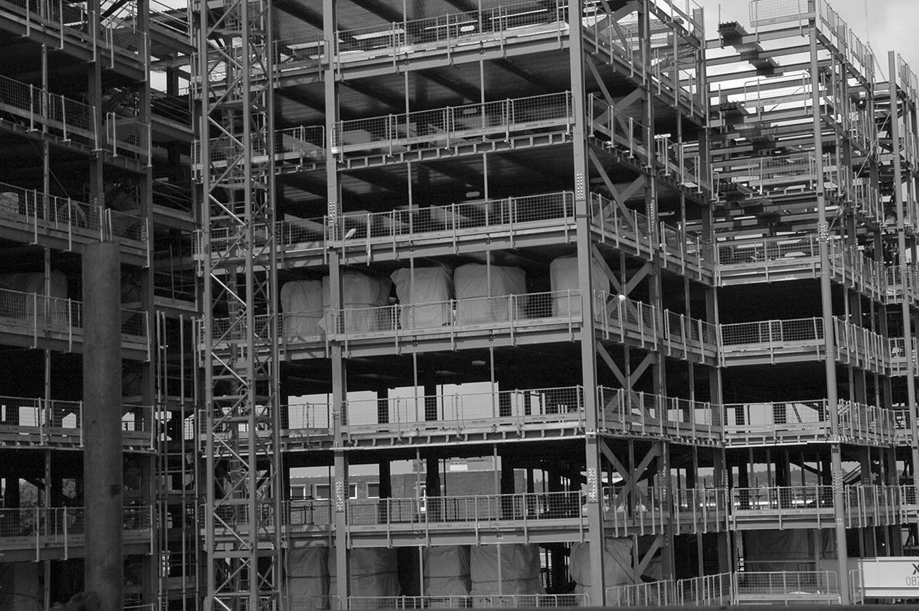
The connections of beams to columns in multi‐storey skeleton steel frames do not generally provide a sufficiently rigid connection to resist the considerable lateral wind forces that tend to cause the frame to rack. The word ‘rack’ is used to describe the tendency of a frame to be distorted by lateral forces that cause right‐angled connections to close up against the direction of the force (in the same way that books on a shelf will tend to fall over if not firmly packed in place). To resist racking caused by the wind forces acting on the faces of a multi‐storey building, it is necessary to include some system of cross bracing between the members of the frame to maintain the right‐angled connection of members (see Photograph 6.4). The system of bracing used will depend on the rigidity of the connections, the exposure, height, shape and construction of the building.

Photograph 6.4 Wind bracing.
The frame for a ‘point block’ building, where the access and service core is in the centre of the building and the plan is square or near square, is commonly braced against lateral forces by connecting cross braces in the two adjacent sides of the steel frame around the centre core which are not required for access, as illustrated in Figure 6.16. Wind loads are transferred to the braced centre core through solid concrete floors acting as plates or by bracing steel‐framed floors.
Figure 6.16 Wind bracing to central core.
With the access and service core on one face of a structural frame, as illustrated in Figure 6.17, it may be convenient to provide cross bracing to the opposite sides of the service core, leaving the other two sides free for access and natural lighting for toilets, respectively. The bracing to the service core makes it a vertical cantilever anchored to the ground. To transfer wind forces acting on the four faces of the building, either one or more of the floors or roof are framed with horizontal cross bracing which is tied to the vertical bracing of the service core. The action of the vertical cross bracing to the service core and the connected horizontal floor cross bracing to a floor, or floor and roof, will generally provide adequate stiffness against wind forces.
Figure 6.17 Wind bracing to access core and floors.
A slab block is a building that is rectangular on plan with two main wall faces much wider than the end walls, as illustrated in Figure 6.18 and Photographs 6.5 and 6.6. With this design, it may be reasonable to accept that the smaller wind forces acting on the end walls will be resisted by the many connections of the two main walls and the horizontal solid plate floors. Here cross bracing to the end walls acting with the horizontal plates of the many solid floors may well provide adequate bracing against wind forces. To provide fire protection to means of escape, service and access cores to multi‐storey buildings, it is common to construct a solid cast in situ reinforced concrete core to contain lifts and escape stairs. A reinforced concrete core by its construction and foundation will act as a very stiff vertical cantilever capable of taking wind forces. To provide wind bracing to a point block, multi‐storey structural steel frame with a central reinforced concrete access core, illustrated in Figure 6.19, it is necessary to transfer wind forces, acting on the walls, to the core. The systems of bracing that are used combine bracing through solid concrete floor plates and cross bracing to structural steel floors. The type of cross bracing illustrated in Figure 6.19 takes the form of braced girders hung from the frame to the four corners of the building and carried back, below floor level, and tied to the core to act as hung, cantilevered cross wind bracing.
Figure 6.18 Wind bracing to end walls.
Photograph 6.5 Wind bracing to the end of a wall.
Photograph 6.6 Wind bracing around stairs.

Figure 6.19 Reinforced concrete core supporting cantilever beams and steel hangers.
Connections and fasteners
The usual practice is to use long lengths of steel column between which shorter lengths of beam are connected, to minimise the number of column to column joints and for the convenience of setting beam ends on shelf angles bolted to columns. In making the connections of four beam ends to a column, it is usual to connect the ends of main beams to the thicker material of column flanges and the secondary, more lightly loaded beam ends to the thinner web material. The ready cut beams are placed on the shelf or seating angles, which have been shop or site bolted to columns, as illustrated in Figure 6.20. The beam ends are bolted to the projecting flanges of the shelf angles. Angle side cleats are bolted to the flange of columns and webs to main beams, and angle top cleats to the web of columns and flanges of secondary beams. The side and top cleats serve the purpose of maintaining beams in their correct position. Where convenient, angle cleats are bolted to columns and beams in the fabricator’s shop to reduce site connections to a minimum. These simple cleat connections can be accurately and quickly made to provide support and connections between beams and columns.
Figure 6.20 Four‐beam to column connection.
An alternative to the simple cleat connection is to use end plates welded to the ends of the beams (Figure 6.21 and Photograph 6.7). The end plate is predrilled with holes that are accurately positioned to line in with predrilled holes in the steel column. The plate can then be bolted to the beam to form a more rigid connection, which will transfer some bending forces (Photograph 6.8).
Figure 6.21 Beam connection using end plates welded to the beam.
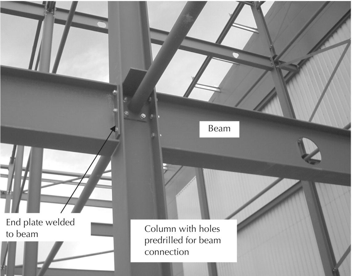
Photograph 6.7 Column and beam connection using end plates welded to the beam.
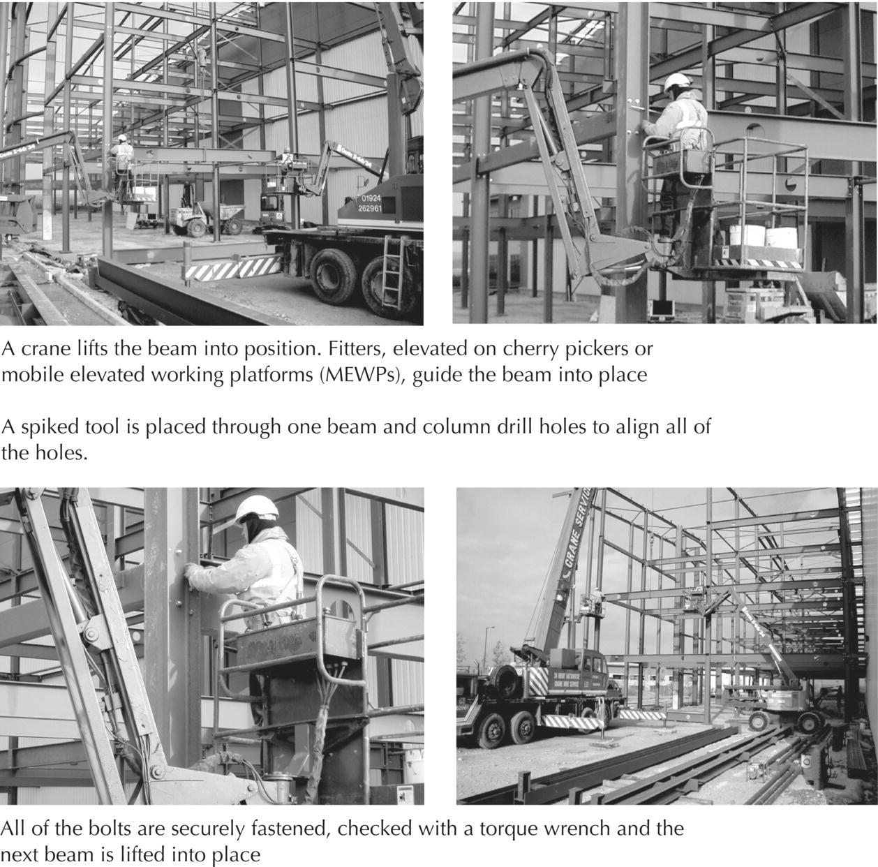
Photograph 6.8 Rigid steel frame assembly – fixing beams to columns.
Cleat connections of beam to column (Figure 6.20) are generally assumed to provide a simple connection in structural analysis and calculation, as there is little restraint to simple bending by this type of end connection of beams. This simply supported (unrestrained) connection is the usual basis of design calculations for structural steel frames as the simple connection provides little restraint to bending, whereas a welded end connection is rigid and affects beam bending.
Figure 6.22 is an illustration of the connection of a main beam to a column on the external face of a building, with the external face beam connected across the outside flanges of external columns. The internal beam is supported by a bottom seating angle cleat and top angle cleat. The external beam is fixed continuously across the outer face of columns to provide support for external walling or cladding that is built across the face of the frame. This beam is supported on a beam cutting to which a plate has been welded to provide a level seating for the beam and for bolt fixing to the beam. The beam cutting is bolted to the flange of columns. A top angle cleat is bolted to the beam and column to maintain the beam in its correct upright position.

Figure 6.22 External beam to column connection.
The connection of long column lengths up the height of a structural steel frame is usually made some little distance above floor beam connections, as illustrated in Figure 6.23. The ends of columns are accurately machined flat and level. Cap plates are welded to the ends of columns in the fabricator’s shop and drilled ready for site bolted connections. Columns for the top floors of multi‐storey buildings will be less heavily loaded than those to the floors below and it may be possible to use a smaller section of column. The connection of these dissimilar section columns is effected through a thick bearing plate welded to the machined end of the lower column and splice plates welded to the outer flange faces. The thick bearing plate will transfer the load from the smaller section column to that of the larger column. The splice plates provide a means of joining the columns. The upper column is hoisted into position on the bearing plate, and packing plates are fitted into place to make up the difference between the column sections. The connection is then made by bolts through the splice plates, packing pieces and flanges of the upper column, as illustrated in Figure 6.24. It is also common to splice columns together using a bolted connection, as shown in Figure 6.25 and Photograph 6.9. Where for design purposes a column is required to take its bearing on a main beam, a simple connection will suffice. A bearing plate is welded to the machined end of the column, ready for bolting to the top flange of the main beam, as illustrated in Figure 6.26a. Where a secondary beam is required to take a bearing from a main beam, as for example, where a floor is trimmed for a stair well, the end of the secondary beam is notched to fit under and around the top flange of the main beam. The connection is made with angle cleats bolted each side of the web of the secondary beam and to the web of the main beam, as illustrated in Figure 6.26b.
Figure 6.23 Column to column connection.
Figure 6.24 Small to larger column connection.
Figure 6.25 Column‐to‐column spliced‐bolted connection.
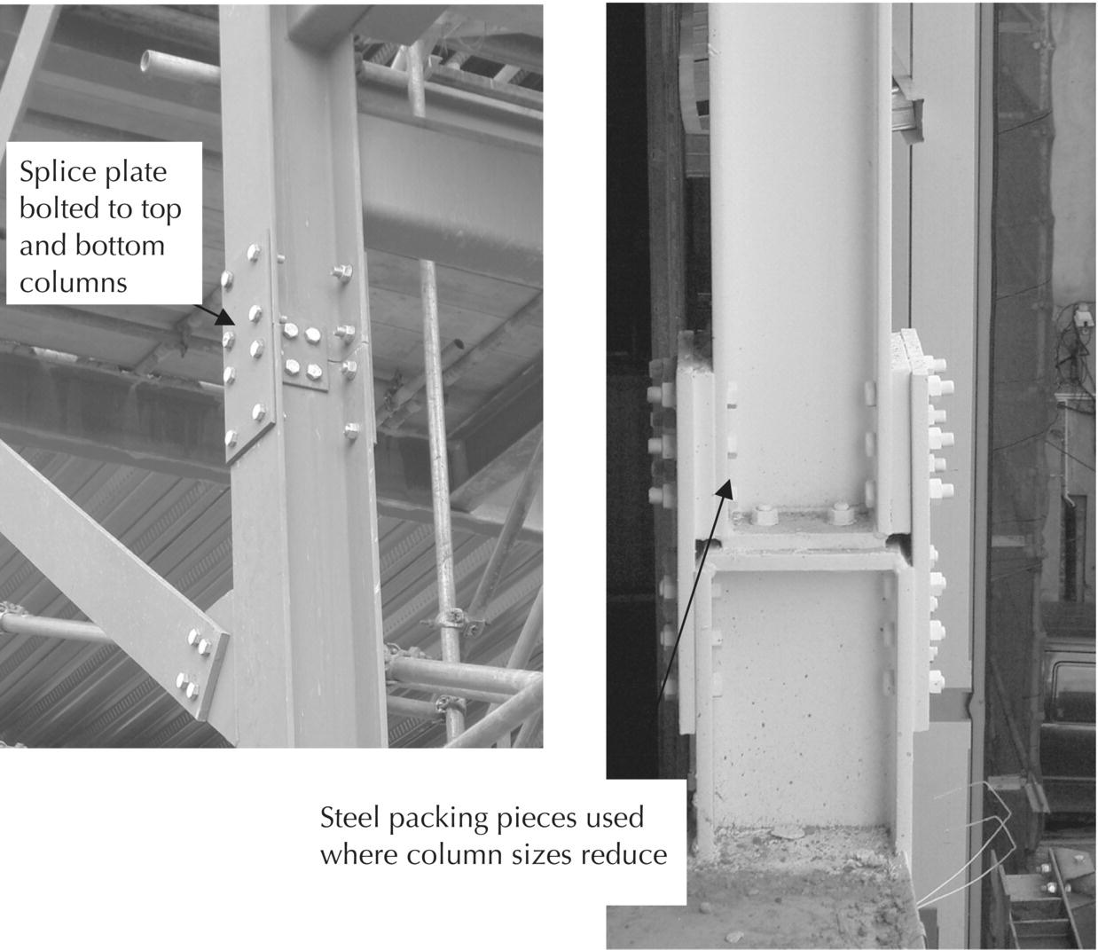
Photograph 6.9 Spliced column connection.

Figure 6.26 (a) Column to beam connection. (b) Beam to beam connection.
Fasteners
Rivets were used as both shop and field (site) fasteners for structural steelwork up to the early 1950s. Today, rivet fasteners are rarely used and bolts are used as fasteners for site connections, with welding for some shop connections. Site bolting requires less site labour than riveting, requires less skill, is quieter and eliminates fire risk.
Hexagon headed black bolts
For many years, hexagon headed black bolts and nuts, illustrated in Figure 6.27, were used for structural steel connections made on site. These bolts were fitted to holes 2 mm larger in diameter than that of the shank of the bolt for ease of fitting. The nut was tightened by hand and the protruding end of the shank of the bolt was burred over the nut by hammering to prevent the nut working loose. The operation of fitting these bolts, which does not require any great degree of skill, can be quickly completed. The disadvantages of this connection are that the bolts do not make a tight fit into the holes to which they are fitted and there is the possibility of some slight movement in the connection. For this reason, black bolts are presumed to have less strength than fitted bolts and their strength is taken as 80 N/mm2. These bolts are little used today for structural steel connections.
Figure 6.27 Black hexagon bolt.
Turned and fitted bolts
To obtain more strength from a bolted connection, it may be economical to use steel bolts that have been accurately turned. These bolts are fitted to holes of the same diameter as their shank, and the bolt is driven home by hammering and then secured with a nut. Because of their tight fit, the strength of these bolts is taken as 95 N/mm2. These bolts are more expensive than black bolts and have largely been superseded by high‐strength friction grip (hsfg) bolts.
High‐strength friction grip bolts
High‐strength friction grip bolts are made from high‐strength steel, which enables them to suffer greater stress due to tightening than ordinary bolts. The combined effect of the greater strength of the bolt itself and the increased friction due to the firm clamping together of the plates being joined makes these bolts capable of taking greater loads than ordinary bolts. Bolts are tightened with a torque wrench, which measures the tightness of the bolt by reference to the torque applied, which in turn gives an accurate indication of the strength of the connection. Hand tightening would give no measure of strength. Though more expensive than ordinary bolts, these bolts and their associated washers are commonly used.
Strength of bolted connections – single shear, double shear
Bolted connections may fail under load for one of two reasons. First, they may fail by the shearing of their shank. Shear is caused by the action of two opposite and equal forces acting on a material. The simplest analogy is the action of the blades of a pair of scissors or shears on a sheet of paper. As the blades close, they exert equal and opposite forces which tear through the fibres of the paper, forcing one part up and the other down. In the same way, if the two plates move with sufficient force in opposite directions, then the bolt joining them will fail in a single shear, as illustrated in Figure 6.28. The strength of a bolt is determined by its resistance to shear in accordance with the strengths previously noted. Where a bolt joins three plates, it is liable to failure by the movement of adjacent plates in opposite directions, as illustrated in Figure 6.28. Failure is caused by the shank failing in shear at two points simultaneously, hence the term double shear. It is presumed that a bolt is twice as strong in double as in single shear.

Figure 6.28 Shear failure.
Bearing strength
A second type of failure that may occur at a connection is caused by the shank of a bolt bearing so heavily on the metal of the member or members it is joining that the metal becomes crushed, as illustrated in Figure 6.29. The strength of the mild steel used in the majority of steel frames and the connections, in resisting crushing, is taken as 200 N/mm2. The bearing area of a bolt on the mild steel of a connection is the product of the diameter of the bolt and the thickness of the thinnest member of the joint. When selecting the diameter and the number of bolts required for a connection, the shear resistance of the bolts and the bearing area of the thinnest plate have to be taken into account.
Figure 6.29 Bearing failure.
Bolt pitch (spacing)
If bolts are too closely spaced, they may bear so heavily on the section of the members around them that they tear through the metal, with the result that, instead of the load being borne by all, it may be transferred to a few bolts which may then fail in shear. To prevent the possibility of this type of failure, it is usual to space bolts at least two and a half times their diameter apart. The distance apart is measured centre to centre. Bolts should be at least one and three quarter times their diameter from the edge of the steel member.
6.5 Welding
The term ‘welding’ describes the operation of running molten weld metal into the heated junction of steel plates or members so that, when the weld metal has cooled and solidified, it strongly binds them together. The edges of the members to be joined are cleaned and also shaped for certain types of weld. For a short period, the weld metal is molten as it runs into the joint, and for this reason it is obvious that a weld can be formed more readily with the operator working above the joint than in any other position. Welding can be carried out more quickly and accurately in a workshop where the members can be manipulated more conveniently for welding than they can be on site. Welding is most used in the prefabrication of built‐up beams, trusses and lattice frames. The use of shop welded connections for angle cleats to conventional skeleton frames is less than it was due to the possibility of damage to the protruding cleats during transport, lifting and handling of members.
In the design of welded structures, it is usual practice to prefabricate as far as practical in the workshop and to make site connections either by bolting or by designing joints that can readily be welded on site. The advantage of welding as applied to structural steel frames is that members can be built up to give the required strength for minimum weight of steel, whereas standard members do not always provide the most economical section. The labour cost in fabricating welded sections is such that it can only be justified in the main for long‐span and non‐traditional frames. The reduction in weight of steel in welded frames may often justify higher labour costs in large, heavily loaded structures. In buildings where the structural frame is partly or wholly exposed, the neat appearance of the welded joints and connections is an advantage. It is difficult to tell from a visual examination whether a weld has made a secure connection, and X‐ray or sonic equipment is the only exact way of testing a weld for adequate bond between weld and parent metal. This equipment is somewhat bulky to use on site, and this is one of the reasons why site welding is not favoured.
Surfaces to be welded must be clean and dry if the weld metal is to bond to the parent metal. These conditions are difficult to achieve in the UK’s wet climate out on site. The process of welding used in structural steelwork is ‘fusion welding’, in which the surface of the metal to be joined is raised to a plastic or liquid condition, so that the molten welding metal fuses with the plastic or molten parent metal to form a solid weld or join. For fusion welding, the requirements are a heat source, usually electrical, to melt the metal, a consumable electrode to provide the weld metal to fill the gap between the members to be joined, and some form of protection against the entry of atmospheric gases which can adversely affect the strength of the weld. The metal of the members to be joined is described as the parent or base metal and the metal deposited from the consumable electrode, the weld metal. The fusion zone is the area of fusion of weld metal to parent metal.
The method of welding most used for structural steelwork is the arc welding process, where an electric current is passed from a consumable electrode to the parent metals and back to the power source. The electric arc from the electrode to the parent metals generates sufficient heat to melt the weld metal and the parent metal to form a fusion weld. The processes of welding most used are:
- Manual metal‐arc (MMA) welding
- Metal inert‐gas (MIG) and metal active‐gas (MAG) welding
- Submerged arc (SA) welding
MMA welding
MMA welding, a manually operated process, is the oldest and the most widely used process of arc welding. The equipment for MMA welding is simple and relatively inexpensive, and the process is fully positional in that welding can be carried out vertically and even overhead due to the force with which the arc propels drops of weld metal on to the parent metal. Because of its adaptability, this process is suitable for complex shapes, welds where access is difficult and on‐site welding. The equipment consists of a power supply and a hand‐held, flux‐covered, consumable electrode, as illustrated in Figure 6.30. As the electrode is held by hand, the soundness of the weld depends largely on the skill of the operator in controlling the arc length and speed of movement of the electrode. The purpose of the flux coating to the electrode is to stabilise the arc, provide a gas envelope or shield around the weld to inhibit pickup of atmospheric gases, and produce a slag over the weld metal to protect it from the atmosphere. Because this weld process depends on the skill of the operator, there is a high potential for defects.

Figure 6.30 MMA welding.
MIG and MAG welding
The processes of MIG and MAG welding use the same equipment, which is more complicated and expensive than that needed for MMA welding. In this process, the electrode is continuously fed with a bare wire electrode to provide weld metal, and a cylinder to provide gas through an annulus to the electrode tip to form a gas shield around the weld, as illustrated in Figure 6.31a. The advantage of the continuous electrode wire feed is that there is no break in welding to replace electrodes as there is with MMA welding, which can cause weakness in the weld run, and the continuous gas supply ensures a constant gas shield protection against the entry of atmospheric gases which could weaken the weld. The manually operated electrode of this type of welding equipment can be used by less highly trained welders than the MMA electrode. The bulk of the equipment and the need for shelter to protect the gas envelope limit the use of this process to shop welding.
Figure 6.31 (a) MIG welding. (b) Automatic SA welding.
SA welding
SA welding is a fully automatic bare wire process of welding where the arc is shielded by a blanket of flux that is continuously fed from a hopper around the weld, as illustrated in Figure 6.31b. The equipment is mounted on a gantry that travels over the weld bench to lay down flux over the continuous weld run. The equipment, which is bulky and expensive, is used for long continuous shop weld runs of high quality, requiring less skilled welders.
Types of weld
Two types of weld are used, the fillet weld and the butt weld.
Fillet weld
The fillet weld takes the form of a fillet of weld metal deposited at the junction of two parent metal membranes to be joined at an angle, the angle usually being a right angle in structural steelwork. The surfaces of the members to be joined are cleaned and the members fixed in position. The parent metals to be joined are connected to one electrode of the supply and the filler rod to the other. When the filler rod electrode is brought up to the join, the resulting arc causes the weld metal to run in to form the typical fillet weld illustrated in Figure 6.32.
Figure 6.32 Fillet weld.
The strength of a fillet weld is determined by the throat thickness multiplied by the length of the weld to give the cross‐sectional area of the weld, the strength of which is taken as 115 N/mm2. The throat thickness is used to determine the strength of the weld, as it is along a line bisecting the angle of the join that a weld usually fails. The throat thickness does not extend to the convex surface of the weld over the reinforcement weld metal, because this reinforcement metal contains the slag of minerals other than iron that form on the surface of the molten weld metal, which are of uncertain strength. The dotted lines in Figure 6.32 represent the depth of penetration of the weld metal into the parent metal and encloses that part of the parent metal that becomes molten during welding and fuses with the molten weld metal.
The leg lengths of fillet weld used in structural steelwork are 3, 4, 5, 6, 8, 10, 12, 15, 18, 20, 22 and 25 mm (Figure 6.32). Throat thickness is the leg length multiplied by 0.7 mm. Fillet welds of 5–22 mm are those most commonly used in structural steelwork, the larger sizes being used at heavily loaded connections. Fillet welds of up to 10 mm are formed by one run of the filler rod in the arc welding process and the larger welds by two or more runs, as illustrated in Figure 6.32. When filled welds are specified by leg length, the steel fabricator has to calculate the gauge of the filler rod and the current to be used to form the weld. An alternative method is to specify the weld as, for example, a 1–10/225 weld, which signifies that it is a 1 run weld with a 10 gauge filler rod to form 225 mm of weld for each filler rod. As filler rods are of standard length, this specifies the volume of the weld metal used for the specified length of weld and therefore determines the size of the weld. Intermittent fillet welds are generally used in structural steelwork, common lengths being 150, 225 and 300 mm.
Butt welds
Butt welds are used to join plates at their edges. The weld metal fills the gap between them. The section of the butt weld employed depends on the thickness of the plates to be joined and whether welding can be executed from one side only or from both sides. The edges of the plates to be joined are cleaned and shaped as necessary, the plates are then fixed in position and the weld metal run in from the filler rod. Thin plates up to 5 mm thick, require no shaping of their edges and the weld is formed, as illustrated in Figure 6.33. Plates up to 12 mm thick have their edges shaped to form a single V weld, as illustrated in Figure 6.34. The purpose of the V‐section is to allow the filler rod to be manipulated inside the V to deposit weld metal throughout the depth of the weld without difficulty. Plates up to 24 mm thick are joined together either with a double V weld, where welding can be carried out from both sides, or by a single U, where welding can only be carried out from one side.
Figure 6.33 Butt welds.

Figure 6.34 Single V butt weld.
Figure 6.35 is an illustration of a double V and a single U weld. The U‐shaped weld section provides room to manipulate the filler rod in the root of the weld but uses less of the expensive weld metal than would a single V weld of similar depth. It is more costly to form the edges of plates to the U‐shaped weld than it is to form the V‐shaped weld, and the U‐shaped weld uses less weld metal than does a V weld of similar depth. Here the designer has to choose the weld that will be the cheapest. Plates over 24 mm thick are joined with a double U weld, as illustrated in Figure 6.35. Butt welds between plates of dissimilar thickness are illustrated in Figure 6.35.
Figure 6.35 Butt welds.
The throat thickness of a butt weld is equal to the thickness of the thinnest plate joined by the weld, and the strength of the weld is determined by the throat thickness multiplied by the length of the weld to give the cross‐sectional area of throat. The size of a butt weld is specified by the throat thickness; that is, the thickness of the thinnest plate joined by the weld. The shape of the weld may be described in words as, for example, a double V butt weld or by symbols.
Uses of welding in structural frames
Welding can often be used economically in fabricating large‐span beams, whereas it is generally cheaper to use standard beam sections for medium and small spans. Figure 6.36 is an illustration of a built‐up beam section fabricated from mild steel strip and plates, fillet and butt welded together. It will be seen that the material can be disposed to give maximum thickness of flange plates at mid‐span where it is needed. Figure 6.37 illustrates a welded beam end connection, where strength is provided by increasing the size of the plates, which are shaped for welding to the column.

Figure 6.36 Welded built‐up long‐span beam.

Figure 6.37 Welded beam to column connection.
Built‐up columns
Columns particularly lend themselves to fabrication by welding, where a fabricated column may be preferable to standard rolled steel sections. The advantages of these fabricated hollow section columns are that the sections may be designed to suit the actual loads, connections for beams and roof frames can be simply made to the square faces, and the appearance of the column may be preferred where there is no necessity for fire‐resistant casing. Hollow section columns are fabricated by welding together angle or channel sections or plates, as illustrated in Figure 6.38. The advantage of columns fabricated by welding two angle or channel sections together is the least weld length necessary. The disadvantage is the limited range of sections available. The benefit of welding four plates together is the facility of selecting the precise thickness and width of plate necessary structurally, and the disadvantage is the length of weld necessary. The considerable extra cost of fabricating built‐up sections limits their use to one‐off special structural designs.

Figure 6.38 Welded built‐up columns.
Column bases and foundations
Because of the comparatively small section area of a steel column, it is necessary to weld a steel base plate to it to provide a flat base to bear on the foundation and so spread the load, and to provide a means of fixing with holding‐down bolts. The bases of steel columns are accurately machined so that they bear truly on the steel base plates to which they are welded. The three types of steel base plate that are used are the plate base, the gusseted plate base, and the slab or bloom base. For comparatively light loads, it is usual to use a 12 mm thick steel base plate fillet welded to the column. The thin plate is sufficient to spread the light loads over its area without buckling. The plate, illustrated in Figures 6.39 and 6.40, is of sufficient area to provide holes for holding‐down bolts.

Figure 6.39 Column base fixed to holding‐down bolts.

Figure 6.40 Column base plate.
Prior to the column being positioned, the foundation base is checked for level, and steel shims are used to ensure that the base of the column sits at the required level. The column is hoisted into position over the concrete base so that it is plumb (vertical). The column is then lowered over the bolts. Because the bolts are cast with a void around them, which allow a small amount of moment (lateral tolerance), wedges are used to move the base into the correct position. The base is checked for line and level before being grouted in. A small bund wall of sand is then positioned around the column base and non‐shrinking grout is then poured between the base and the foundation. The grout fills all the voids, including those made by the cones, which had allowed movement. Once the grout has set, the column is securely held in position.
The purpose of the levelling concrete or grout that is run between the base plate and the concrete is to provide uniform contact between the level underside of the plate and the irregular surface of the concrete foundation. A wet (liquid) mix of self‐levelling expanding cement is poured between the column and foundation, and a temporary bund wall is used to ensure that the liquid grout is contained. As the grout dries and hardens, it expands slightly.
A gusseted base plate may also be used to spread the load of the column over a sufficient area of plate. The machined column base is fillet welded to the base plate and four shaped steel gusset plates are welded to the flanges of the column and the base plate, as illustrated in Figure 6.41. The gusset plates effectively spread the loads from the column over the area of the base plate. The column is hoisted into position so that it is plumb, and steel wedges are driven in between the plate and the concrete base ready for levelling concrete or grout. The word ‘slab’ or ‘bloom’ is used to describe comparatively thick, flat sections of steel that are produced by the process of hot rolling steel ingots to shape. A slab or bloom is thicker than a plate. Slab or bloom bases for steel columns are used for the benefit of their ability to spread heavy loads over their area without buckling. The machined ends of columns are fillet welded to slab bases and the columns hoisted into position until plumb. Steel wedges are driven in between the base and the concrete foundation ready for holding‐down bolts and grouting. Figure 6.42 is an illustration of a slab base.

Figure 6.41 Gusseted base plate.

Figure 6.42 Slab base plate.
Steel column bases are secured in position on concrete foundations, with two, four or more holding‐down bolts. These bolts are termed ‘holding‐down’, because they hold the columns in position and may hold columns down against uplift that may occur due to the effect of wind pressure on the faces of tall buildings.
Holding‐down bolts may be cast into concrete foundations by themselves or inside collars, which make allowance for locating bolts in the correct position. To cast the expanded metal collars in concrete, they are supported by timber templates which are supported at the sides of bases. Figure 6.43 is an illustration of a timber template supporting collars ready for casting into a concrete base. The advantage of these collars is that they allow some little adjustment for aligning the holes in steel bases with the position for casting in holding‐down bolts. The boss shown in the diagram at the top of collars is a wood plug to hold the bolts in the correct position. The frame holds the bolts at the correct line and level (Photograph 6.10). Once the column is in position, grout is run to fill the collars around the holding‐down bolts, which are fitted with anchor plates to improve contact with the concrete. Another method of fixing holding‐down bolts is to drill holes in dry concrete bases and to use expanding bolts in the drilled holes. This necessitates a degree of accuracy in locating the position for drilling holes to coincide with the holes in base plates.

Figure 6.43 Temporary bolt boxes.
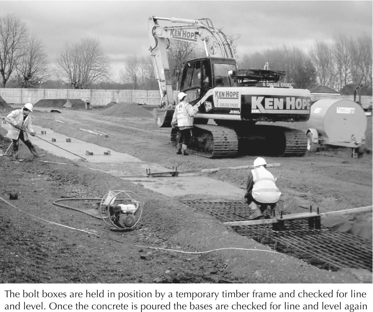
Photograph 6.10 Positioning of holding‐down bolts – bolt boxes.
(Source: courtesy of G. Throup).
Mass concrete foundation to columns
The base of columns carrying moderate loads of up to, say, 400 kN bearing on soils of good bearing capacity can be formed economically of mass concrete. The size of the base depends on the bearing capacity of the soil and load on the column base, and the depth of the concrete is equal to the projection of the concrete beyond the base plate, assuming an angle of dispersion of load in concrete of 45°.
Reinforced concrete base
The area of the base required to spread the load from heavily loaded columns on subsoils of poor to moderate bearing capacity is such that it is generally more economical to use a reinforced concrete base than a mass concrete one. The steel column base plate is fixed as it is to a mass concrete base. Where column bases are large and closely spaced, it is often economical to combine them in a continuous base or raft. When a heavily reinforced concrete base is used, it may be possible to tie and position the bolt boxes to the reinforcement cage prior to pouring the concrete, rather than erecting a temporary timber frame.
Steel grillage foundation
The steel grillage foundation is a base in which a grillage of steel beams transmits the column load to the subsoil. The base consists of two layers of steel beams, two or three in the top layer under the foot of the column and a lower cross layer of several beams so that the area covered by the lower layer is sufficient to spread column loads to the requisite area of subsoil. The whole of the steel beam grillage is encased in concrete. This type of base is rarely used today, as a reinforced concrete base is much cheaper.
Hollow rectangular sections
Beam to column connections
Bolted connections to closed box section columns may be made with long bolts passing through the section. Long bolts are expensive and difficult to use as they necessitate raising beams on opposite sides of the column at the same time in order to position the bolts. Beam connections to hollow rectangular and square section columns may be made through plates, angles or tees welded to the columns. Standard beam sections are bolted to T‐section cleats welded to columns and lattice beams by bolting end plates welded to beams to plates welded to columns, as illustrated in Figure 6.44.

Figure 6.44 Connections to hollow section columns.
Flowdrill jointing
A recent innovation in making joints to hollow rectangular steel (HRS) sections is the use of the flowdrill technique as an alternative to using either long bolting through the hollow sections or welding and site bolting. The flowdrill technique depends on the use of a tungsten carbide bit (drill), which can be used in a conventional power operated drill. As the tungsten carbide bit rotates at high speed on the surface of the steel, friction generates sufficient heat to soften the steel. As the bit penetrates the now softened wall of the steel section, it redistributes the metal to form an internal bush, as illustrated in Figure 6.45. Once the metal has cooled, the formed internal bush is threaded with a coldform flowtap bit to make a threaded hole ready for a bolt. The beam connection to the hollow steel column is completed by bolting welded on end plates or bolting to web cleats welded to the column through the ready drilled holes. The execution of this form of connection requires a good deal of skill in setting out centre punched holes accurately in the face of the hollow section to align exactly the holes to be drilled. Flowdrill jointing is the preferred method of making site connections to hollow sections for the benefit of economy in materials and site labour, and the security of the bolted connection.

Figure 6.45 Flowdrill jointing.
Cold strip sections
Beam to column connections
Beam to column connections are made by means of protruding studs or T’s welded to the columns and bolted to the beams. Studs welded to columns are bolted to small section beams and ties, and larger section beams to T‐section cleats welded to columns, as illustrated in Figure 6.46. The T‐section cleat is required for larger beams to spread the bearing area over a sufficient area of thin column wall to resist buckling.

Figure 6.46 Cold roll‐formed sections – connections.
6.6 Fire protection of structural steelwork
To limit the growth and spread of fires in buildings, the Regulations classify materials in accordance with the tendency of the materials to support spread of flame over their surface, which is also an indication of the combustibility of the materials. Regulations also impose conditions to contain fires inside compartments to limit the spread of flame. To provide safe means of escape, the Regulations set standards for the containment of fires and the associated smoke and fumes from escape routes for notional periods of time deemed adequate for escape from buildings.
One aspect of fire regulations is to specify notional periods of fire resistance for the loadbearing elements of a building so that they will maintain their strength and stability for a stated period during fires in buildings for the safety of those in the building. Steel, which is non‐combustible and makes no contribution to fire, loses so much of its strength at a temperature of 550 °C that a loaded steel member would begin to deform, twist and sag and no longer support its load. Because a temperature of 550 °C may be reached early in the development of fires in buildings, regulations may require a casing to structural steel members to reduce the amount of heat getting to the steel. The larger the section of a structural steel member, the less it will be affected by heat from fires, by absorbing heat before it loses strength. The greater the mass and the smaller the perimeter of a steel section, the longer it will be before it reaches a temperature at which it will fail. This is due to the fact that larger sections will absorb more heat than smaller ones before reaching a critical temperature.
The traditional method of protecting structural steelwork from damage by fire is to cast concrete around beams and columns or to build brick or blockwork around columns with concrete casing to beams. These heavy, bulky and comparatively expensive casings have by and large been replaced by lightweight systems of fire protection employing sprays, boards, preformed casing and intumescent coatings. The materials used for fire protection of structural steelwork may be grouped as:
- Spray coatings
- Board casings
- Preformed casings
- Plaster and lath
- Concrete, brick or block casings
Spray coatings
A wide range of products is available for application by spraying on the surface of structural steel sections to provide fire protection. The materials are sprayed on to the surface of the steel sections so that the finished result is a lightweight coating that takes the profile of the coated steel, as illustrated in Figure 6.47. This is one of the cheapest methods of providing a fire protection coating or casing to steel for protection of up to 4 hours, depending on the thickness of the coating. The finished surface of these materials is generally coarse textured and, because of the lightweight nature of the materials, these coatings are easily damaged by knocks and abrasions. They provide some protection against corrosion of steel and, being lightweight, assist in controlling condensation. These sprayed systems of protection are suitable for use where appearance is not a prime consideration and for beams in floors above suspended ceilings. Being lightweight and porous, spray coatings are not generally suited to external use. Spray coatings may be divided into three broad groups as described further.
Figure 6.47 Fire protection of structural steelwork by sprayed limpet casing.
Mineral fibre coatings
Mineral fibre coatings consist of mineral fibres that are mixed with inorganic binders, the wet mix being sprayed directly on to the clean, dry surface of the steel. The material dries to form a permanent, homogenous insulation that can be applied to any steel profile.
Vermiculite/gypsum/cement coatings
Vermiculite/gypsum/cement coatings consist of mixes of vermiculite or aerated magnesium oxychloride with cement or vermiculite with gypsum plaster. The materials are premixed and water is added on site for spray application directly to the clean, dry surface of steel. The mix dries to a hard, homogenous insulation that can be left rough textured from spraying or trowelled to a smooth finish. These materials are somewhat more robust than mineral spray coatings but will not withstand knocks. The use of sprayed vermiculite has declined, but still can be found in existing buildings (see Photograph 6.11).
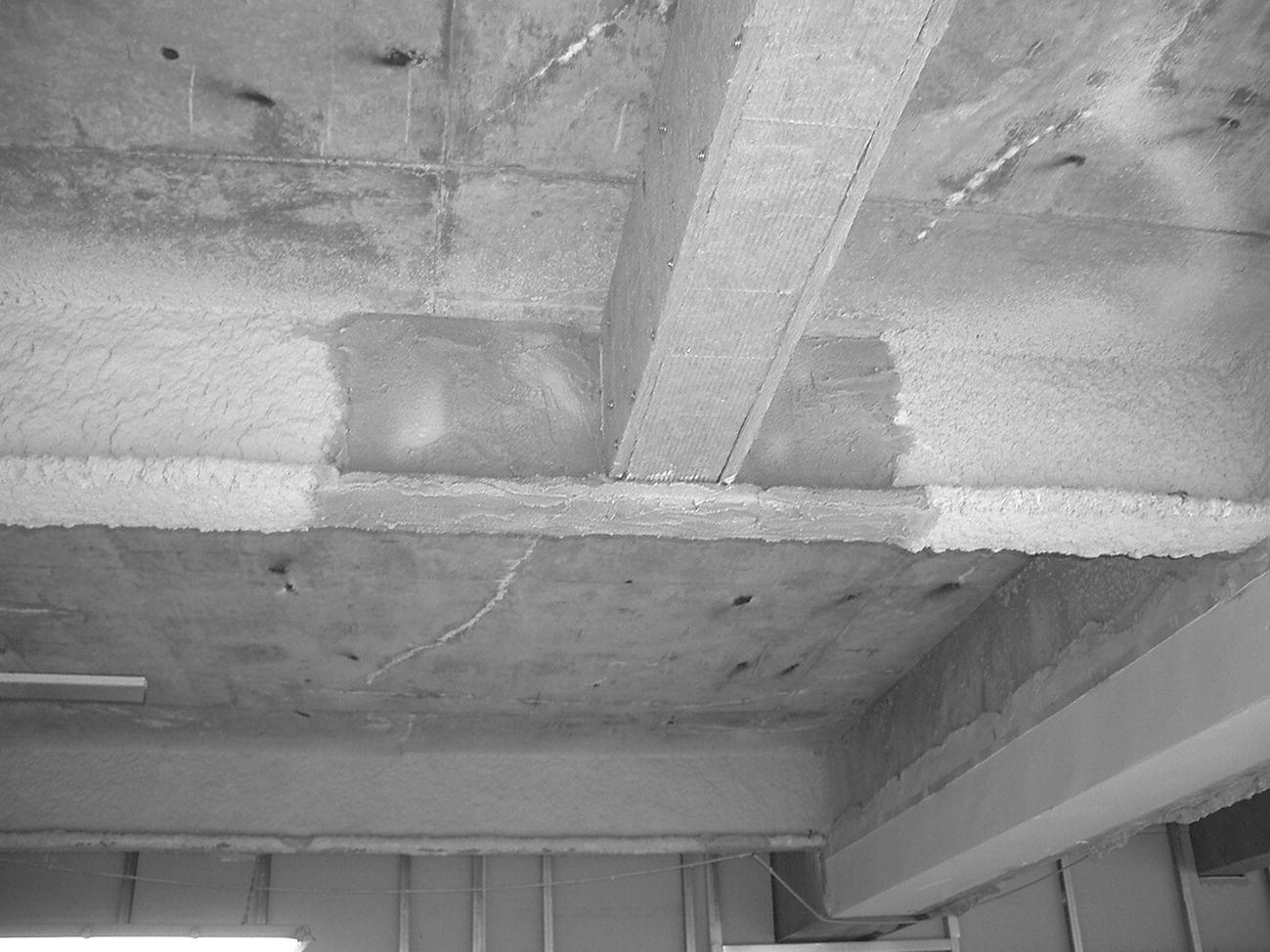
Photograph 6.11 Steel covered in mineral board fire protection connected to existing steel beam with vermiculite coating.
Intumescent coatings
Intumescent coatings include mastics and paints which swell when heated to form an insulating protective coat which acts as a heat shield. The materials are applied by spray or trowel to form a thin coating over the profile of the steel section (see Photograph 6.12). They provide a hard finish which can be left textured from spraying or trowelled smooth, and provide protection of up to 2 hours.
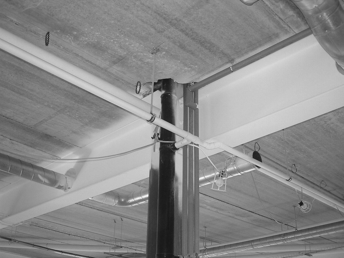
Photograph 6.12 Intumescent fire protection that covers the steel beam. The column will also need protection from impact damage.
Board casings
There is a wide choice of systems based on the use of various preformed boards that are cut to size and fixed around steel sections as a hollow, insulating fire protection. Board casings may be grouped in relation to the materials that are used in the manufacture of the boards that are used as:
- Mineral fibreboards or batts
- Vermiculite/gypsum boards
- Plasterboard
For these board casings to be effective as fire protection, they must be securely fixed around the steel sections, and joints between boards must be covered, lapped or filled to provide an effective seal to the joints in the board casing. Board casings are only moderately robust and can be easily damaged by moderate impacts; therefore, they are not suitable for external use. Board casings are particularly suitable for use in conjunction with ceiling and wall finishes.
Mineral fibreboards and batts
Mineral fibreboards and batts are made of mineral fibres bound with calcium silicate or cement. The surface of the boards and batts, which is coarse textured, can be plastered. These comparatively thick boards are screwed to light steel framing around the steel sections (see Photograph 6.13). Mineral fibre batts are semi‐rigid slabs which are fixed by means of spot welded pins and lock washers. Mineral fibreboards are moderately robust and are used where appearance is not a prime consideration.
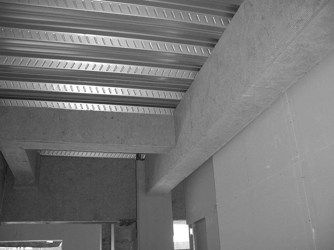
Photograph 6.13 Mineral fibreboard fire protection.
Vermiculite/gypsum boards
Vermiculite/gypsum boards are manufactured from exfoliated vermiculite and gypsum or non‐combustible binders (see Photograph 6.14). The boards are cut to size and fixed around steelwork, either to timber noggins wedged inside the webs of beams and columns or screwed together and secured to steel angles or strips, as illustrated in Figure 6.48. The edges of the boards may be square edged or rebated. The boards, which form a rigid, fairly robust casing to steelwork, can be self‐finished or plastered.
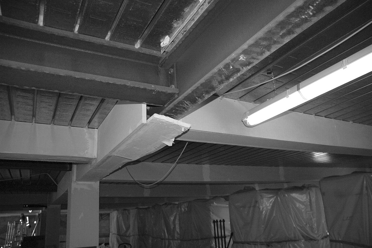
Photograph 6.14 Gypsum board fire protection.
Figure 6.48 Vermiculite/gypsum board.
Plasterboard casings
Plasterboard casings can be formed from standard thickness plasterboard or from a board with a gypsum/vermiculite core for improved fire resistance. The boards are cut to size and fixed to metal straps around steel sections. The boards may be self‐finished or plastered. This is a moderately robust casing. Figure 6.49 is an illustration of a board casing.
Figure 6.49 Board casing.
Preformed casings
Preformed casings are made in preformed ‘L’ or ‘U’ shapes ready for fixing around the range of standard column or beam sections, respectively. The boards are made of vermiculite and gypsum, or with a sheet steel finish on a fire‐resisting lining, as illustrated in Figure 6.50. The vermiculite and gypsum boards are screwed to steel straps fixed around the steel sections and the sheet metal‐faced casings by interlocking joints and screws. These preformed casings provide a neat, ready finished surface, with good resistance to knocks and abrasions in the case of the metal‐faced casings.
Figure 6.50 Preformed casings.
Plaster and lath casings
Plaster on metal lath casing is one of the traditional methods of fire protection for structural steelwork. Expanded metal lath is stretched and fixed to stainless steel straps fixed around steel sections with metal angle beads at arrises, as illustrated in Figure 6.51. The lath is covered with vermiculite gypsum plaster to provide an insulating fire‐protective casing that is trowelled smooth, ready for decoration. This rigid, robust casing can suffer abrasion and knocks and is particularly suitable for use where a similar finish is used for ceilings and walls.

Figure 6.51 Metal lath and plaster casing.
Concrete, brick or block casing
An in situ cast concrete casing provides fire protection to structural steelwork and protection against corrosion. This solid casing is highly resistant to damage by knocks. To prevent the concrete spalling away from the steelwork during fires, it is lightly reinforced, as illustrated in Figure 6.52. The disadvantages of a concrete casing to steelwork are its mass, which considerably increases the deadweight of the frame, and the cost of on‐site labour and materials in the formwork and falsework necessary to form and support the wet concrete.
Figure 6.52 Concrete fire protection.
Brick casings to steelwork may be used where brickwork cladding or brick division or compartment walls are a permanent part of the building, or where a brick casing is used for appearance’s sake to match surrounding fairface brick. A brick casing is an expensive, labour‐intensive operation in the necessary cutting and bonding of brick around columns.
Blockwork may be used as an economic means of casing columns, particularly where blockwork divisions or walls are built up to structural steelwork. The labour in cutting and bonding these larger units is considerably less than with bricks. The blocks encasing steelwork are reinforced in every horizontal joint with steel mesh or expanded metal lath.
6.7 Floor construction for structural steel frames
Functional requirements
The functional requirements of floors are:
- Strength and stability
- Durability and freedom from maintenance
- Fire safety
- Resistance to the passage of heat (for party floors and exposed floors)
- Resistance to the passage of sound
Strength and stability
The requirements from the Building Regulations are that buildings be constructed so that the loadbearing elements, foundations, walls, floors and roofs have adequate strength and stability to support the dead loads of the construction and anticipated loads on roofs, floors and walls without such undue deflection or deformation as might adversely affect the strength and stability of parts or the whole of the building. Strength and stability of floors depend on the nature of the materials used in the floor elements, and the section of the materials used in resisting deflection (bending) under the dead and imposed loads. Under load, any horizontal element will deflect (bend) to an extent. Deflection under load is limited to about 1/300 of span to minimise cracking of rigid finishes to floors and ceilings and to limit the sense of insecurity the occupants might have, were the floor to deflect too obviously. In general the strength and stability of a floor or roof is a product of the depth of the supporting members: the greater the depth, the greater the strength and stability.
Durability and freedom from maintenance
Durability and freedom from maintenance of floors constructed with steel beams, profiled steel decking and reinforced concrete depend on the internal conditions of the building. The majority of multi‐storey‐framed buildings today are heated and ventilated, so that there is little likelihood of moist internal conditions occurring, such as to cause progressive, destructive corrosion of steel during the useful life of the building.
Fire safety
The practical guidance given in Approved Document B is directed to the safe escape of people from buildings in case of fire rather than the protection of the building and its contents. Insurance companies that provide cover against the risks of damage to the buildings and contents by fire will generally require additional fire protection such as sprinklers and detection equipment.
Internal fire spread
Fire may spread within a building over the surface of materials covering walls and ceilings. Regulations prohibit the use of materials that encourage spread of flame across their surface when subject to intense radiant heat and those which give off appreciable heat when burning. Limits are set on the use of thermoplastic materials used in rooflights and lighting diffusers. As a measure of ability to withstand the effects of fire, the elements of a structure are given notional fire resistance times, in minutes, based on tests. Elements are tested for the ability to withstand the effects of fire in relation to:
- Resistance to collapse (loadbearing capacity), which applies to loadbearing elements
- Resistance to fire penetration (integrity), which applies to fire separating elements (e.g. floors)
- Resistance to the transfer of excessive heat (insulation), which applies to fire separating elements
The notional fire resistance times, which depend on the size, height and use of the building, are chosen as being sufficient for the escape of occupants in the event of fire. The requirements for the fire resistance of elements of a structure do not apply to:
- A structure that supports only a roof, unless:
- the roof acts as a floor (e.g. car parking), or as a means of escape
- the structure is essential for the stability of an external wall, which needs to have fire resistance
- the lowest floor of the building
To prevent rapid fire spread that could trap occupants, and to reduce the chances of a fire growing large, it is necessary to subdivide buildings into compartments separated by walls and/or floors of fire‐resisting construction. The degree of subdivision into compartments depends on:
- The use and fire load (contents) of the building
- The height of the floor of the top storey as a measure of ease of escape and the ability of fire services to be effective
- The availability of a sprinkler system, which can slow the rate of growth of fire
The necessary compartment walls and/or floors should be of solid construction, sufficient to resist the penetration of fire for the stated notional period of time in minutes. The requirements for compartment walls and floors do not apply to single storey buildings.
Smoke and flame may spread through concealed spaces, such as voids above suspended ceilings, roof spaces and enclosed ducts and wall cavities in the construction of a building. To restrict the unseen spread of smoke and flames through such spaces, cavity barriers and stops should be fixed as a tight‐fitting barrier to the spread of smoke and flames.
Resistance to the passage of heat
The requirements for the conservation of power and fuel by the provision of adequate insulation of floors are described in Barry’s Introduction to Construction of Buildings.
Resistance to the passage of sound
In multi‐storey buildings, the structural frame may provide a ready path for the transmission of impact sound over some considerable distance. The slamming of a door, for example, can cause a sudden disturbing sound clearly heard some distance from the source of the sound by transmission through the frame and floor members. Unexpected sounds are often more disturbing than continuous background sounds such as external traffic noise. To provide resistance to the passage of sound it is necessary to provide a break in the path between potential sources of impact and continuous solid transmitters. Solid concrete floors tend to be relatively good at not transmitting sound, compared to timber and steel; however, this is influenced by the type of floor finish.
Precast hollow floor beams
The precast, hollow, reinforced concrete floor units illustrated in Figure 6.53 are from 400 to 1200 mm wide, 110 to 300 mm thick for spans of up to 10 m for floors and 13.5 m for the less heavily loaded roofs. The purpose of the voids in the units is to reduce deadweight without affecting strength. The reinforcement is cast into the webs between the hollows. The wide floor units are used where there is powered lifting equipment which can swing the units into place. These hollow floor units can be used as floor slabs with a non‐structural levelling floor screed; alternatively they may be used with a structural reinforced concrete topping with tie bars over beams for composite action with the concrete casing to beams. Raised floor finishes can also be applied directly to the unfinished surface.
Figure 6.53 Hollow precast floor units.
The end bearing of these units is a minimum of 75 mm on steel shelf angles or beams and 100 mm on masonry and brick walls. The ends of these floor units are usually supported by steel shelf angles either welded or bolted to steel beams so that a part of the depth of the beam is inside the depth of the floor, as illustrated in Figure 6.54 and Photograph 6.15.

Figure 6.54 Hollow precast floor units on steel beam

Photograph 6.15 Installation of hollow precast concrete floor beams.
(Source: courtesy of G. Throup).
The ends of the floor units may be splayed to fit under the top flange of the beams. A disadvantage of the construction shown in Figure 6.54 is that the deep I‐section beam projects some distance below the floor units and increases the overall height of construction for a given minimum clear height between the floor and the underside of the beam. Welded top hat profile beams with the floor units supported by the bottom flange, as illustrated in Figure 6.55, may be used to minimise the overall height of the construction.

Figure 6.55 Top hat section beam.
The top hat section is preferred because of the difficulty of lowering and manoeuvring the units into the web of broad flange I‐section beams. This construction method is particularly suited to multi‐storey residential flats, where the comparatively small imposed loads on floors facilitate a combination of overall beam depth and floor units to minimise construction depth. A screed is spread over the floor for lightly loaded floors and roofs, and a reinforced concrete constructional topping for more heavily loaded floors.
Precast prestressed concrete floor units
Precast prestressed concrete floor units are comparatively thin, prestressed solid plank, concrete floor units are designed as permanent centring (shuttering) for composite action with structural reinforced concrete topping, as illustrated in Figure 6.56. The units are 400 and 1200 mm wide, 65, 75 or 100 mm thick and up to 9.5 m long for floors and 10 m for roofs. It may be necessary to provide some temporary propping to the underside of these planks until the concrete topping has gained sufficient strength. A disadvantage of this construction is that as the planks are laid on top of the beams so that the floor spans continuously over beams, there is increase in overall depth of construction from top of floor to underside of beams.

Figure 6.56 Prestressed solid plank floor unit.
Precast beam and filler block floor
The precast beam and filler block floor system of precast reinforced concrete beams or planks to support precast hollow concrete filler blocks is illustrated in Figure 6.57. For use with steel beams, the floor beams are laid between supports such as steel shelf angles fixed to the web of the beams or laid on the top flange of beams, and the filler blocks are then laid between the floor beams. The reinforcement protruding from the top of the planks acts with the concrete topping to form a continuous floor system spanning across the structural beams. These small beams or planks and filler blocks can be positioned without the need for heavy lifting equipment. This type of floor is most used in smaller‐scale buildings supporting the lighter imposed floor loads common in residential buildings, for example.
Figure 6.57 Precast beam and filter block floor.
Hollow clay block and concrete floor
The hollow clay block and concrete floor system, illustrated in Barry’s Introduction to Construction of Buildings, consists of hollow clay blocks and in situ cast concrete reinforced as ribs between the blocks. This floor has to be laid on temporary centring to provide support until the in situ concrete has gained sufficient strength and is labour intensive.
Precast concrete T‐beams
Precast concrete T‐beam floors are mostly used for long‐span floors and particularly roofs of such buildings as stores, supermarkets, swimming pools and multi‐storey car parks, where there is a need for wide‐span floors and roofs, and the depth of the floor is no disadvantage. The floor units are cast in the form of a double T, as illustrated in Figure 6.58. The strength of these units is in the depth of the tail of the T, which supports and acts with the comparatively thin top web. A structural reinforced concrete topping is cast on top of the floor units.
Figure 6.58 Prestressed concrete double T‐beam.
Cold‐rolled steel deck and concrete floor
The traditional concrete floor to a structural steel frame consisted of reinforced concrete, cast in situ with the concrete casing to beams, cast on timber centring and falsework supported at each floor level until the concrete had sufficient strength to be self‐supporting. The considerable material and labour costs in erecting and striking the support for the concrete floor led to the adoption of the precast concrete self‐centring systems such as the hollow beam and plank, and beam and infill block floors. The term ‘self‐centring’ derives from the word ‘centring’ used to describe the temporary platform of wood or steel on which in situ cast concrete is formed. The precast concrete beam, plank and beam, and block floors do not require temporary support, hence the term self‐centring. A disadvantage of the precast concrete beam and plank floors for use with a structural steel frame is that it is usual practice to erect the steel frame in one operation. Raising the heavy, long precast concrete floor units and moving them into position is, to an extent, impeded by the skeleton steel frame.
Profiled cold‐rolled steel decking
Profiled cold‐rolled steel decking, as permanent formwork, acting as the whole or a part of the reinforcement to concrete, has become the principal floor system for structural steel frames (see Photographs 6.16 to 6.19). The profiled steel deck is easily handled and fixed in place as formwork (centring) for concrete. The profiled cold roll‐formed, steel sheet decking, illustrated in Figure 6.59, is galvanised on both sides as a protection against corrosion. The profile is shaped to bond to the concrete, using projections that taper in from the top of the deck. Another profile is of trapezoidal section with chevron embossing for key to concrete. The steel deck may be laid on the top flange of beams, as illustrated in Figure 6.69, or supported by shelf angles bolted to the web of the beam to reduce overall height and fixed in position on the steelwork with shot fired pins, self‐tapping screws or by welding, with two fixings to each sheet. Side laps of deck are fixed at intervals of not more than 1 m with self‐tapping screws or welding.
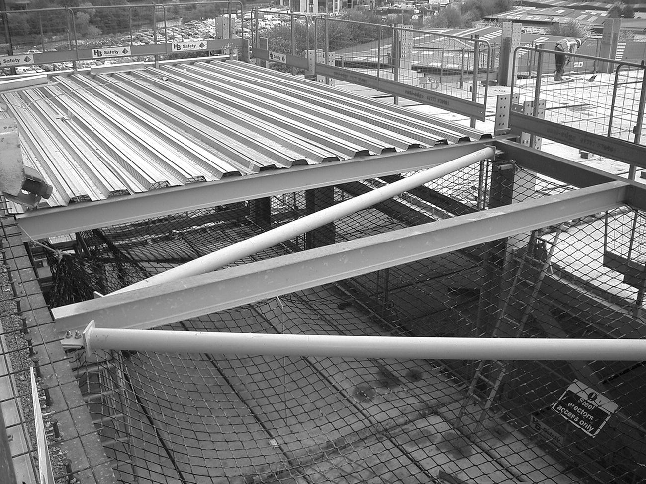
Photograph 6.16 Steel deck floor.
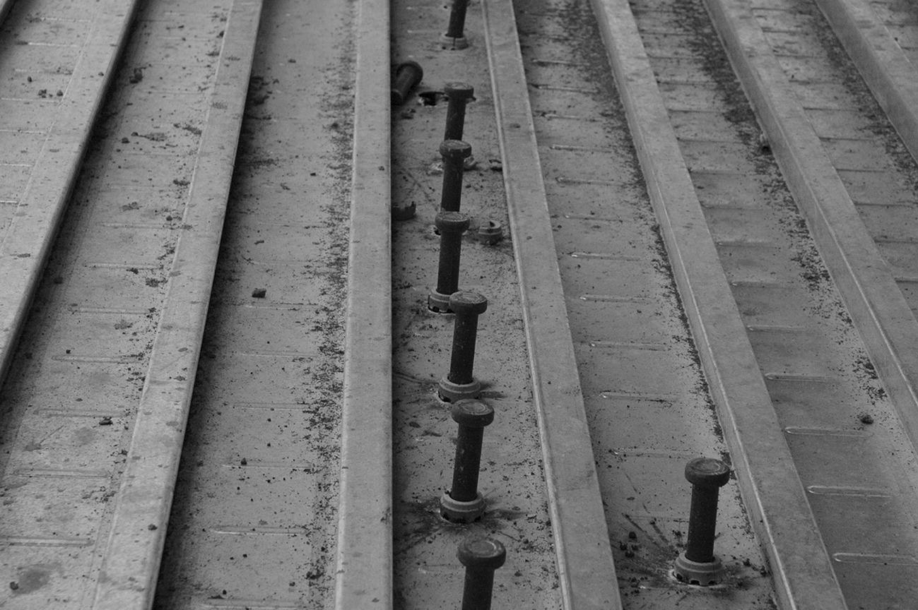
Photograph 6.17 Composite construction – studs welded to the steel frame embedded in the concrete.

Photograph 6.18 Boxing out to leave a service void in the concrete floor.
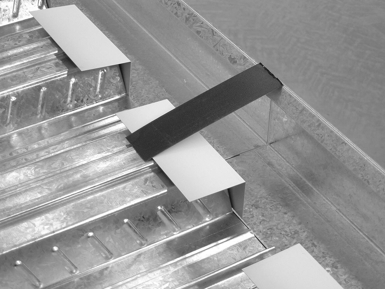
Photograph 6.19 Permanent steel deck floor – formwork for the floor and edge of the composite floor.

Figure 6.59 Steel deck and concrete floor.
For medium spans between structural steel beams, the profiled steel deck acts as both permanent formwork and as reinforcement for the concrete slab that is cast in situ on the deck.
A mesh of anti‐crack reinforcement is cast into the upper section of the slab, as illustrated in Figure 6.59. For long spans and heavy loads, the steel deck can be used with additional reinforcement cast into the bottom of the concrete between the upstanding profiles and, for composite action between the floor and the beams, shear studs are welded to the beams and cast into the concrete. The steel mesh reinforcement cast into the concrete slab floor is sufficient to provide protection against damage by fire in most situations. For high fire rating, the underside of the deck can be coated with sprayed‐on protection or an intumescent coating. Where there is to be a flush ceiling for appearance and as a housing for services, a suspended ceiling is hung from hangers slotted into the profile or hangers bolted to the underside of the deck.
For particularly large spans or where cuts are made through the profile metal sheet for services, some temporary propping is required until the concrete has reached its 7 day maturity.
Slimfloor floor construction
‘Slimfloor’ is the name adopted by British Steel (now Corus) for a form of floor construction for skeleton steel‐framed buildings. This form of construction is an adaptation of a form of construction developed in Sweden, where restrictions on the overall height of buildings dictated the development of a floor system with the least depth of floor construction to gain the maximum number of storeys within the height limitations. Slimfloor construction comprises beams fabricated from universal column sections to which flange plates are welded, as illustrated in Figure 6.60. The flange plates, which are wider overall than the flanges of the beams, provide support to profiled steel decking that acts in part as reinforcement and provides support for the reinforced concrete constructional topping. The galvanised, profiled steel deck units are 210 mm deep with ribs at 600 mm centres. The ribs and the top of the decking are ribbed to stiffen the plates and to provide some bond to concrete. To seal the ends of the ribs in the decking, to contain the concrete that will be cast around beams, sheet steel stop ends are fixed through the decking to the flange plates, as illustrated in Figure 6.61. Constructional concrete topping is spread over the decking and into the ribs around reinforcement in the base of the ribs and anti‐crack reinforcement in the floor slab.

Figure 6.60 Slimfloor beam.

Figure 6.61 Slimfloor construction.
The galvanised pressed steel deck units are designed for spans of 6 m for use with the typical grid of 9 m beam spans at 6 m centres. For spans of over 6 m and up to 7.5 m, the decking will need temporary propping at mid‐span until the concrete has developed adequate strength. The slimfloor may be designed as a non‐composite form of construction where the floor is assumed to have no composite action with the beams, as illustrated in Figure 6.61. This non‐composite type of floor construction is usual where the imposed floor loads are low, as in residential buildings, and the floor does not act as a form of bracing to the structural frame. A particular advantage of the slimfloor is that all or some of the various services, common to some modern buildings, may be accommodated within the deck depth rather than being slung below the structural floor over a false ceiling. Calculations and tests have shown that 150 mm diameter holes may be cut centrally through the web of the beams at 600 mm spacing along the middle third of the length of the beam without significantly affecting the load‐carrying capacity of the beam. Figure 6.61 is an illustration of the floor system showing a plastic tube sleeve run through the web of a beam for service pipes and cables.
The ceiling finish may be fixed to the underside of the decking or hung from the decking to provide space for services such as ducting. Because of the concrete encasement to the beams, most slimfloor constructions achieve 1 hour’s fire resistance rating without the need for applied fire protection to the underside of the beam. Where fire resistance requirement is over 60 minutes, it is necessary to apply fire protection to the underside of the bottom flange plate.
The advantages of the slimfloor construction are:
- Speed of construction through ease of manhandling and ease of fixing the lightweight deck units, which provide a safe working platform
- Pumping of concrete obviates the need for mechanical lifting equipment
- The floor slab is lightweight as compared with in situ or precast concrete floors
- The deck profile provides space for both horizontal services in the depth of the floor and vertical services through the wide top flange of the profile
- Least overall depth of floor to provide minimum constructional depth consistent with robustness requirements dictated by design codes
Composite construction
Composite construction is the name given to structural systems in which the separate structural characteristics and advantages of structural steel sections and reinforced concrete are combined as, for example, in the T‐beam system. A steel frame, cased in concrete and designed to allow for the strength of the concrete in addition to that of the steel, is a form of composite construction. Where concrete encases steel sections, it is accepted that the stiffening and strengthening effect of the concrete on the steel can be allowed for in engineer’s calculations. By reinforcing the concrete casing and allowing for its composite effect with the steel frame, a saving in steel and a reduction in the overall size of members can be achieved.
Shear stud connectors
A concrete floor slab bearing on a steel beam may be considered to act with the beam and serve as the beam’s compressive flange, as a form of composite construction. This composite construction effect will work only if there is a sufficiently strong bond between the concrete and the steel, to make them act together in resisting shear stresses developed under load. The adhesion bond between the concrete and the top flange of the beam is not generally sufficient, and it is usually necessary to fix shear studs or connectors to the top flange of the beam, which are then cast in the floor slab. The purpose of these studs and connectors is to provide a positive resistance to shear. Figure 6.62 is an illustration of typical shear stud connectors and Figure 6.63 is an illustration of composite floor and beam construction.

Figure 6.62 Shear stud connector.

Figure 6.63 Composite construction.
Inverted T‐beam composite construction
The composite beam and floor construction described earlier employs the standard I‐section beams. The top flange of the beam is not a necessary part of the construction, as the concrete floor slab can be designed to carry the whole of the compressive stress, so that the steel in the top flange of the beam is wastefully deployed. By using an inverted T‐section member, steel is placed in the tension area and concrete in the compression area, where their characteristics are most useful. A cage of mild steel binders, cast into the beam casing and linked to the reinforcement in the floor slab, serves to make the slab and beam act as a form of composite construction by the adhesion bond of the concrete to the whole of the T‐section.
Preflex beams
The use of high‐tensile steel sections for long‐span beams has been limited owing to the deflection of the beams under load, which causes cracking of concrete casing, and possible damage to partitions and finishes. Preflex beams are made by applying and maintaining loads, which are greater than working loads, to pairs of steel beams. In this deflected position, reinforced concrete is cast around the tension flanges of the beams. When the concrete has developed sufficient strength, the load is released and the beams tend to return to their former position. In so doing, the beams induce a compressive stress in the concrete around the tension flange, which prevents the beams from wholly regaining their original shape. The beams now have a slight upward camber. Under loads, the deflection of these beams will be resisted by the compressive stress in the concrete around the bottom flange, which will also prevent cracking of concrete. Further stiffening of the beam to reduce deflection is gained by the concrete casing to the web of the beam. By linking the reinforcement in the concrete web casing to the floor slab, the concrete and steel can be made to act as a composite form of construction. These beams may be connected to steel columns, with end plates welded to beam ends and bolted to column flanges, or may be cast into reinforced concrete columns.
Preflex beams are considerably more expensive than standard mild steel beams and are designed, in the main, for use in long‐span heavily loaded floors. The slimfloor beam may be used in composite construction. For composite action, shear studs are welded to the top flange of a universal column section to which a wide bottom plate has been welded. This bottom plate serves as a bearing for hollow, precast reinforced concrete floor units. Structural concrete topping is spread and consolidated around the beam and as reinforced structural topping around transverse reinforcement, as illustrated in Figure 6.64. The result is a reinforced concrete floor acting compositely with the steel beam, the concrete casing tying to the beam and shear studs. The advantage of this construction is the least depth of floor of uniform depth. This type of floor is more expensive than a straightforward beam and slab floor.
Figure 6.64 Composite floor construction.