
10
Fit Out and Second Fix
Many commercial buildings are often built to a ‘shell’ finish; that is, the main structure of the building is completed, but the internal fittings and decoration is carried out as part of a separate contract (or contracts) to suit client/user requirements. This allows a certain amount of flexibility and choice of finish for those occupying some or all of the building. Electrical trucking and light fittings, suspended floors, suspended ceilings, partition walls, shelving, display units, internal fittings, painting and decorating, and signage all form part of the fit out and second fix operations. In this chapter. the focus is on the more common fit out systems, raised floors, suspended ceilings and internal partition walls.
10.1 Commercial fit out
The term ‘commercial fit out’ is normally used to cover the fit out and second fix to offices, retail units and industrial buildings. The main components of a fit out, the raised floor, suspended ceiling and internal partition walls are described further. The vast majority of raised floor, suspended ceiling and internal partition wall systems are manufactured to a patented design. The quality of the system and adaptability vary between manufacturers, from budget systems to expensive systems for the most prestigious of developments. Careful research is required to choose the most appropriate system to suit the requirements of the building users.
Offices and commercial buildings
Speculative office developments are a common feature in our towns and cities. These are usually built to a relatively standard design and completed to a shell finish under the main contract. At the most basic level, the shell finish includes the structure and external fabric of the building, staircases, lifts and service core. A more common approach is to include the raised floor and suspended ceilings, sanitary fittings and electrical outlets. Internal partition walls are usually installed as part of the fit out to suit the needs of the particular user. The office space is usually leased, and it is not uncommon for users to move to another address, or lease more or less floor space at the end of the rental period. Thus flexibility and adaptability of office space is a prime consideration.
Retail
The term ‘shop fitting’ is used to describe the process of installing the furniture (display shelving and units, points of sale, etc.) and associated equipment (chillers cabinets, freezer cabinets, etc.) to a retail unit. Retail units are usually termed as ‘food retail’ or ‘non‐food retail’, reflecting the accepted use of the unit or building. The vast majority of retail units are designed to be relatively flexible in terms of use. This is because the units will normally be leased out to a particular business for a certain period of time. Thus it is common practice to build the shell of the unit, with the fitting out carried out by the retailer to suit a particular house style (corporate image). This applies to shops located on the high street and also to units located in large shopping centres.
Retailers tend to change their display arrangements on a regular basis. Minor changes can usually be accommodated in adjustable shelving units, but more major changes associated with an update in corporate image usually necessitate a complete refit of the retail unit, often resulting in a lot of wasted materials. Similarly, with a change of retailer there is usually the need for new shop fitting.
Food retail units will require additional drainage points for the condensate drain to freezer cabinets and chiller units. The store layout tends to be changed less frequently because the condensate drains determine the position of freezer and chiller units. Changes in position usually necessitate changes to drain positions, which can be disruptive to the sales area.
Shop signs
Provision for shop signage is usually provided at strategic places on the exterior face of the shop unit and this too will usually be installed (subject to town planning consent) by the organisation leasing the shop. The shop signs are printed on to relatively thin backgrounds (e.g. acrylic sheet) or on to a translucent material so that the sign can be illuminated from behind. The shop sign is then fixed to the face of the wall, usually with screws. From a design perspective, it is important to provide a structure suitable for supporting the signage and any electrical connects required for the lighting.
Industrial
Industrial production facilities have special requirements to suit a particular manufacturing process. These may include one or a number of the following features: clean rooms, security (of staff and materials/processes), wash down facilities, special materials handling areas and secure storage, specialist fire protection systems, etc. These are outside the scope of this book, but readers should be aware that these special requirements have a bearing on the choice of construction methods used and how services are integrated; for example, sealing services as they pass through compartment walls in clean room construction. Often some compromises need to be made. For example, in fast‐track projects, it would be sensible to use prefabricated, framed construction to save time on the building site; however, some production processes may require solid masonry walls.
On fast‐track projects, such as new pharmaceutical production facilities, it has become common practice to manufacture and test industrial plant prior to installation in the building. The equipment is then transported to site, moved into its final position and ‘plugged‐in’. It is then put through a final series of conformity and safety tests; that is, it is commissioned for use. This is usually done while the main build contract is still under way. Large access doors facilitate the delivery and subsequent maintenance and replacement of large pieces of equipment.
10.2 Raised floors
A raised floor (access floor) is used to conceal services, usually electrical cables and air‐conditioning ducts, in the cavity between the raised floor and the structural floor. Raised floors are particularly useful in large open plan spaces, such as offices, where it is not practical to house services in partition walls. Air‐conditioning grilles and services outlets, such as electrical and telephone sockets, can be provided within the floor to provide a flat and even surface finish. The cables and air‐conditioning ducts are hidden from view in the cavity between the raised floor and the structural floor finish, with strategically placed access panels to allow convenient access for repair, maintenance and upgrading, hence the term ‘access floor’. Concealing the cables not only improves the visual appearance of the floor area but also helps to keep trip hazards to a minimum. Most manufacturers of raised floor systems also supply ancillary items such as electrical floor boxes, cable ports and cable management systems. Raised floors can also accommodate safety lighting and can be illuminated from underneath to provide additional visual interest, contributing to mood lighting and also displaying information such as advertising and location maps.
Raised floors are used in new building developments as well as in refurbishment work, where there is sufficient vertical height between structural floors to add a raised floor. By adjusting the depth of the supports to suit uneven floors and changes in floor levels, it is possible to provide a flat‐level surface and eliminate the need for ramps and short flights of stairs.
Functional requirements
The functional requirements are to:
- Accommodate and conceal services:
- Provide ease of access to services
- Allow changes to services below the floor
- Create a clear cavity for services
- Be flexible:
- Provide a level, attractive and durable floor finish
- Accommodate changes in surfaces
- Remove changes in structural floor
- Facilitate changes in level
- Provide required surface level
- Sustain and resist imposed loads:
- Be rigid and stable
- Have good appearance and aesthetics:
- Hide unsightly structural floors
- Present feature in its own right (e.g. lighting)
- Provide sound control:
- Resist passage of impact and airborne sound
- Provide acoustical control (absorption and reflection)
- Provide required thermal resistance and prevent formation of condensation
- Provide protection against fire:
- Control spread of fire and maintain structural stability in a fire
- Be durable:
- Resist wear and tear
- Be easy to maintain:
- Provide safe installation and ease of maintenance
- Provide a comfortable, easy to clean finish
Floor assembly
There are two primary components to a raised floor, the floor panel and the support pedestal. Combined, the components provide a rigid and stable floor surface for a variety of uses. The design life of the floor panels tends to be anything up to 25 years, that of the supports around 50 years. Loading capacity will vary with different systems, usually expressed as a point load over 25 × 25 mm (e.g. 3 kN), and uniformly distributed load (e.g. 8 kN/m2). In situations where heavy furniture or equipment is to be installed, the loading of the system can be improved by the installation of additional support pedestals. Manufacturers will also provide details of the air leakage (at 25 Pa), the fire rating (e.g. Class 0), the combined weight of the system (e.g. 40 kg/m2), which will vary with height, and a statement on electrical continuity of the system (e.g. that it complies with IEE Regulations). Acoustic performance of the system (which depends on the type of floor finish) should also be provided. Floor to wall junctions are usually sealed with an air seal.
Floor panels
Floor panels are manufactured to a nominal size of 600 × 600 mm. Depending on the construction, the depth of the panel will be from around 25 to 40 mm. The majority of panels are constructed of high‐density particleboard encapsulated in a galvanised steel finish, approximately 0.5 mm thick. Non‐metallic systems comprise high‐density particleboard or specially treated moisture‐resistant chipboard, usually applied with a protective finish. It is common in UK properties to install carpet tiles on a trackifier, but timber and marble may also be used. Metallic panels are gravity fitted, laid into the structural support grid using a hand‐held suction device. Indentations in the underside of the panel allow positive location and subsequent retention within the support system. Rapid access is available through the use of a suction device to lift the panels out. The non‐metallic systems tend to be screwed to the structural supports through a countersunk hole at each corner. Unscrewing the panels from the supports provides access.
Support pedestals
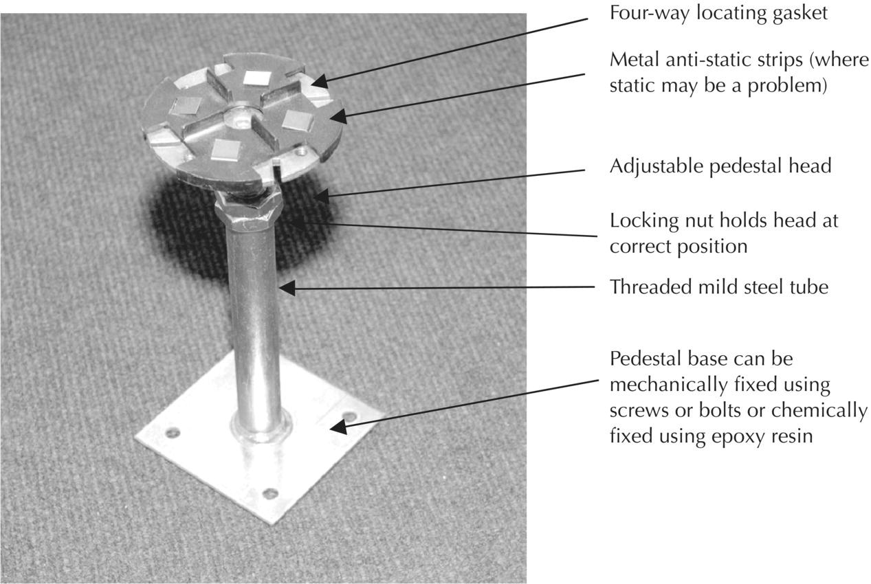
The pedestal is usually constructed of steel. Concrete and timber can also be used. Steel pedestals are adjustable to suit variations in the structural floor (Figures 10.1 and 10.2 and Photographs 10.1 and 10.2). They are fixed on a 600 mm2 grid and a laser level is used to ensure a level finish. Electrical earthing is required when metallic components are used. Angled supports are also manufactured to provide a ramped floor finish. Pedestals are manufactured in a range of heights, providing clear cavity spaces from as little as 30 mm up to 1000 mm.
Figure 10.1 Raised floor pedestal.

Figure 10.2 Raised floor.
Photograph 10.1 Raised floor pedestal.
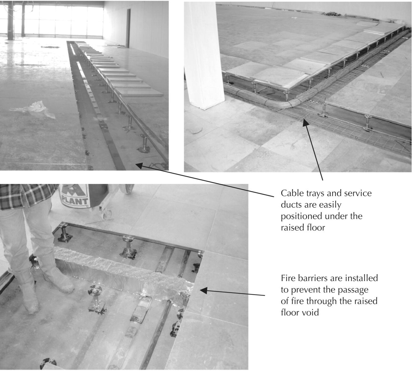
Photograph 10.2 Raised floors.
Example of pedestal and panel floor assembly
- 31 or 32 mm overall galvanised steel/chipboard sandwich panel 600 × 600 mm, which is placed on polypropylene cruciform locating lugs and sits at the top of the pedestal. The panel can be rested on or fixed to the pedestal.
- The pedestal is made of mild steel tube and base plate, with threaded components to allow for adjustment. Locking nuts are also used to hold the pedestals securely at the correct level.
- Pedestals are fixed with polyurethane or epoxy adhesive to sub‐floor at 600 mm centres or mechanically fixed (plug and screw or gun nailed) if the pedestals are over 600 mm high (deep void). As panels are square, pedestals are fixed on a grid based on the module sizes.
- Panels are often constructed from a 0.5 mm steel top and bottom with 30 mm chipboard sandwiched between, or 1 mm steel top and bottom for heavy loading. Other types of panel construction are also available.
- A typical floor depth is about 600 mm, but can be increased to over 2 m (using considerable support, framework).
- Fire barriers should be used under compartment walls and where necessary to prevent the cavity acting as a conduit for fire.
Maintenance
Raised floor cavities need to be regularly cleaned to remove dust and debris. The cavity should be vacuumed using static‐free tools and special air filters at least twice per year. Suction tools can be used to gain easy access into the cavity (Figure 10.2).
10.3 Suspended ceilings
Suspended ceilings are primarily used to provide an attractive finish to the ceiling, while at the same time concealing (and allowing access to) services. A suspended ceiling comprises a lightweight structural grid, which is supported by wire hangers attached to the underside of the structural floor, and into which lightweight tiles are positioned. The structural grid is based on a 600 × 600 mm module. Suspended ceilings may also be used in refurbishment projects to provide a level ceiling finish to areas of the building that differ in height.
Suspended ceilings not only provide an attractive, level ceiling finish, with convenient access to services when required (Photographs 10.3 and 10.4), but are also used to house a wide variety of equipment, which may include ventilation grilles, light fittings, fire sprinklers, detectors (e.g. smoke and heat), security cameras, movement sensors and alarms.

Photograph 10.3 Suspended ceiling.
(Source: courtesy of D. Highfield).

Photograph 10.4 Suspended ceilings: accommodation of services.
(Source: courtesy of G. Throup).
Functional requirements
The functional requirements (adapted from BS 8290: Part 1 1991 Suspended Ceilings Code of Practice for Design) include:
- Concealment of structure. To hide changes in the structure, beams, floors and ties, and to provide a level and attractive ceiling finish.
- Concealment of services. To create a clear cavity for services, hide services such as ducts, equipment and cables, and allow easy access for maintenance.
- Decorative appearance. The aesthetics of finishes are always important.
- Thermal insulation. Thermal insulation may be introduced if the ceiling is adjacent to the roof. It must be designed and positioned to prevent interstitial condensation.
- Acoustic control. Sound insulation and absorption. The two main aspects of acoustic control are absorption of a sound within an enclosed space and the reduction of sound passing through a material or structure. The measures necessary to control these two are different. Sound absorption is achieved by incorporating porous material of a low density in the ceiling. Sound insulation requires an impervious material of a very high density. Mineral wool, with its high density, is often placed on top of the ceiling grid.
- Fire control. Controlling the development and spread of a fire, containing a fully developed fire, and protecting the structure against damage or collapse. A fire‐resisting ceiling should not be confused with a fire‐protecting ceiling; different test methods and criteria apply. A fire‐protecting ceiling offers protection to the structural beams and floors. The term ‘fire protection’ implies that the ceiling can satisfy the stability, integrity and insulation requirements for a stated period. Sprinkler heads and systems may form part of the fire protection system.
- Control of condensation. Placing thermal insulation over a suspended ceiling can increase the risk of interstitial condensation. For guidance on controlling condensation, reference should be made to BS 5250 (Code of Practice for the Control of Condensation in Buildings) and BRE 143 (Thermal Insulation Avoiding Risks).
- Hygiene control. Smooth cleanable finishes may be required to facilitate a clean room.
- Ventilation. The services may form an integral part of the suspended ceiling unit. Where services are concealed within the ceiling, they may need additional support. Each piece of plant can be individually tied to the building structure.
- Heating, air conditioning, illumination. The luminaires may be surface mounted or independently supported from the structure. The ceiling may also be used to control the amount of light reflected and diffused into the room.
- Electrical earthing and bonding. The ceiling grid must be earthed. In the event of any electrical fault, the parts of the ceiling capable of carrying an electrical current are earthed and protected.
Ceiling assembly
A wide variety of ceiling systems are available (Figures 10.3 and 10.4 and Photographs 10.3 and 10.4). There are two primary components to a suspended ceiling, the ceiling tile and the support grid. Combined, the components provide a lightweight and level ceiling finish. The design life of the ceiling tiles tends to be anything up to 25 years, that of the support system around 50 years. The loading capacity of the system is sufficient to carry the weight of the system and associated equipment. Heavy fittings will require independent support from the underside of the structural floor. Manufacturers should also provide details of the air leakage (at 25 Pa), the fire rating (e.g. Class 0) and the combined weight of the system, which will vary slightly with the depth of the hangers. Acoustic performance of the system should also be provided.

Figure 10.3 Suspended ceiling.

Figure 10.4 Suspended ceiling grids.
Ceiling tiles
Ceiling tiles are manufactured to a nominal size of 600 × 600 mm. Tiles are made from gypsum, mineral wool, pressed lightweight steel or a lightweight material, such as particleboard, and usually have a paint finish. The majority of systems rely on a gravity fit, with the tile placed into the grid. In areas where wind uplift may be a problem (e.g. in entrance lobby areas), it is common to provide a more rigid fixing to avoid accidental lifting and damage to the tiles. Most manufacturers produce plain tiles as well as tiles with a variety of preformed apertures into which lights and sensors are placed. Installing perforated tiles can provide additional sound insulation.
Support grid
The support grid is made from lightweight wire hangers, fixed to the underside of the structural floor. These wire hangers support the lightweight modular grid into which the tiles are placed. Special fittings (edge details) are manufactured for intersections at structural columns and the walls. The support grid is set out and levelled using a laser level. The grid can be exposed, semi‐concealed and fully concealed (Figure 10.4 and Photograph 10.4).
Maintenance
Careless handling and repositioning within the grid may damage tiles. To maintain an attractive finish, damaged tiles will need to be replaced. Tiles may also become dusty and marked through careless handling; thus some cleaning may be required.
10.4 Internal partition walls
Internal partition walls are used to create discrete areas within large interior spaces. A wide variety of proprietary systems are available, which are designed for different uses and for different quality levels. Alternatively partition walls may be constructed as a framed structure (in timber or mild steel) or as a masonry wall (brick or block). In office developments, the emphasis tends to be on flexibility and future adaptability of the workspace, while in industrial units, emphasis tends to be more on durability and ability to withstand minor impacts.
The term ‘partition wall’ is used rather loosely in the construction sector to cover both loadbearing and non‐loadbearing internal walls. These have already been described in Barry’s Introduction to Construction of Buildings. In the context of this chapter, we have limited the description of partition walls to some of the more flexible and adaptable systems that are used in commercial developments.
Functional requirements
Partition walls may be free‐standing units positioned on the floor, tied to the structural floor, or tied to the structural floor and the ceiling structure. In buildings with a high roof (e.g. conversion schemes), it is not uncommon for the partition wall to be supported off the floor only and a suspended ceiling installed to create a sensible ceiling height in relation to the room proportions. Alternatively partition walls may be used to define space only, supported off the floor and without the need for ceilings. All partition wall systems need to be structurally stable and, especially in office space, easy to reposition without causing damage to floor or ceiling finishes.
Functional requirements are:
- Flexibility
- Adaptability
- Structural stability
Other performance requirements, which the partition wall may need to address, include:
- Fire resistance
- Resist the spread of fire
- Accommodate services
- Provide required acoustic and thermal insulation
- Transfer own weight and any fixtures and fittings (non‐loadbearing)
- Transfer building loads (loadbearing)
- Allow the passage of light
- Allow cross ventilation
- Demountability
Fire resistance
The partition may be required to prevent the passage of fire acting as a compartment wall. Blockwork with a plastered finish provides a good resistance to fire; for example, a 100 mm block wall finished with plaster easily offers 2 hours’ fire resistance, and a double skin plastered blockwork wall will achieve fire resistance of 4 hours. Timber stud and proprietary walls only offer half an hours’ fire resistance, unless they are specifically designed as a fire‐resisting structure. There are many fire‐resisting plasterboards that can be easily applied to stud walls in single, double and triple thicknesses. All joints must be effectively sealed with fire stops. Any gaps, services ducts, ventilation units, doors and windows provide weaknesses in fire‐resisting structures and should be addressed in the detailing. It may be possible for the fire to pass around the wall under raised floors or suspended ceilings; effective fire barriers should be provided under and above the wall, if it forms a compartment wall.
Fire‐resisting walls should be fire stopped at their perimeter, at junctions with other fire‐resisting walls, floors and ceilings, openings around doors, pipes and cables. Fire stopping materials include:
- Mineral wool
- Cement mortar
- Gypsum plaster
- Intumescent mastic or tape (intumescent strip)
- Proprietary sealing systems
Figure 10.5 provides an example of a fire‐resisting partition.
Figure 10.5 Fire‐resisting or acoustic metal stud partition wall.
Resist the spread of fire
The surface material should not allow flames to pass across it and should not fuel the fire. In public buildings, walls should be designed so that the risk of flame spreading across the surface is minimal. Compartment walls must have a low risk of spread of flame (Class 0).
Accommodate services
Allow for maintenance and repositioning of services. Some proprietary partitions are prefabricated with conduits, pipework or cables already positioned. Skirting boards and dado rails are often a good place to provide access for services. Conduits and channels run behind plastic, metal or wooden boards, and entry boxes are positioned to allow services to be installed. Alternatively, the services would need to be surface mounted.
With timber stud walls, timber grounds can be easily positioned to accommodate electrical plug sockets, pipework and other fittings. Steel and timber stud walls have become increasingly popular in flats and offices. However, when installing services within these walls, care should be taken to ensure that the acoustic and fire‐resisting properties of the wall are not compromised by the penetration of services through the plasterboard. Ideally, services should be surface mounted to avoid the problem. Alternatively sound‐resisting material, such as acoustic‐resisting plasterboard, should be positioned in the middle of the wall with timber or metal studs on either side of the panel, thus allowing services to be accommodated without affecting the sound‐resisting material (Figure 10.5).
With masonry walls, the services can be surface mounted or chased into the wall. Chasing should not exceed one‐third of the wall’s thickness vertically and one‐sixth horizontally. Chases in the wall will reduce the strength, acoustic properties and fire resistance. Care should be taken to ensure that these do not compromise the specified performance.
Provide required acoustic control
The degree of sound absorption and reflection in a room is particularly important in auditoriums, lecture theatres, concert halls, etc. Lightweight porous materials will help to absorb the sound and reduce reflection, whereas heavy, hard, smooth surfaces will reflect the sound. In an auditorium or lecture theatre, reflective surfaces should be used close to the source of the sound (e.g. position of the speaker) and absorbent materials should be used towards the back of the room, where noises reflecting would cause an echo.
Transfer own weight and any fixtures mounted on the wall
The ability of a partition wall to accept fixtures and fittings is often overlooked. Overloading a wall with shelves or other fittings may cause the wall itself to break or topple over, or the load of the fittings may simply pull the fittings out of the wall fabric. The wall materials must be capable of restraining the loads applied. Studs and other reinforcing materials may need to be positioned so that the wall can accommodate the load. The head of the wall will also need to be restrained if loads are anything other than minimal.
Transfer building loads (loadbearing)
While it is common to have large, flexible open spaces divided by non‐loadbearing, potentially demountable walls, it is often economical to have intermediate loadbearing supports, such as internal walls. The walls can be loadbearing, carrying loads from floors, beams and components above the wall down to the building’s foundations. By using intermediate loadbearing walls, the floor beams do not need to span as far, and the section and depth of each beam can be reduced. Smaller, shallower beams are less expensive per unit length than long, deep section beams.
Allow the passage of light
Light may be allowed to pass with or without vision through the material (usually glass). Windows and vision panels are easily introduced into stud and masonry walls. It is important that the windows are carefully selected and fitted so that they comply with the other performance criteria of the wall (e.g. fire resistance and acoustic properties).
Allow cross ventilation
Mechanical and natural ventilation ducts may be installed through the wall. If the wall is a compartment wall, these service ducts will need to be fitted with a fire stop that is capable of sealing the duct in the event of a fire.
Demountability of partition walls
To accommodate changes of use, large spaces are often divided using demountable partitions. In such situations the ease with which a wall can be dismantled, reassembled and repositioned is of considerable importance. Any non‐load bearing wall is demountable, but it may not be possible to re‐erect the structure using the same components.
Some patent partition walls have been designed so that they can be easily repositioned (e.g. folding concertina doors, sliding doors or walls), without the need for tools. Others are bolted, clipped or fixed into place but can be relatively easily repositioned with minimum disruption. Continuity of floor, wall and ceiling finishes may sometimes be compromised when partition walls are repositioned or removed.
Partition wall assembly
Partition walls are manufactured to a modular size. Systems are usually based on a lightweight steel stud system. Alternatively timber studs may be used (Figure 10.6). By using multiple layers of acoustic or gypsum fire‐resisting plasterboard and filling the studs with mineral wall, the fire‐resisting and sound‐reducing properties of the wall can be significantly increased.
Figure 10.6 Timber stud partition wall.
Often selected purely on economic grounds, different arrangements of brick, timber, concrete, steel and patent systems can be selected to provide the required finish, flexibility, acoustics and fire‐resisting properties, as illustrated in Figure 10.7.

Figure 10.7 Types of internal partition.