Previous chapters introduced the Raspberry Pi hardware, and you learned how to use Python to program it. You installed the operating system, configured it for your use, and set up remote access so that you can program the Pi without connecting a keyboard, mouse, and monitor directly to it. You learned the basic structure of a Python program, syntax, and enough about the language to start writing programs.
Next, you are going to learn how to use the Raspberry Pi’s GPIO interface to interact with the physical world. This is crucial for robotics because it’s how the processor detects what is happening around it and responds to outside stimuli. Without the capability to detect and act on the physical world, any kind of intelligent autonomy is not possible.
Raspberry Pi GPIO
There are several ways to connect to the Raspberry Pi. By far the simplest is through one of the USB ports built into the board. The USB ports provide four serial connections through which you can access outside components, such as the keyboard and mouse we used to set up the Pi. However, the USB port requires special hardware to convert the serial commands to the signals needed to operate the device. The Raspberry Pi has a more direct method of connecting to external devices: the GPIO header.

Raspberry Pi with 40-pin header
Although the Raspberry Pi is powered with a 5-volt USB micro adapter, the electronics are 3.3 volts. This means that you need to pay attention to the voltages that the sensors use.
There are two voltages supplied on the GPIO pins: 5V and 3.3V. Be careful which one you are using, especially if attempting to power the Pi through GPIO.
It is possible to power the Raspberry Pi through one of the 5V GPIO pins; however, circuit protection and regulation is not provided. If you supply too much voltage, or there is a current spike, the board may be damaged. If you must use the GPIO pins to power the board, be sure to provide an external regulator.
There are two numbering schemas for the GPIO header: board and BCM. This means that there are two different ways to reference the pins from your code; the one that you decide to use is generally up to you. You just have to remember which schema you chose to go with.
Pin Numbering
As I mentioned, there are two numbering schemas for the 40-pin header: board and BCM.
Board numbering simply numbers the pins sequentially. Pin 1 is the one closest to the micro SD card, and pin 2 is the adjacent pin closest to the outer edge of the Pi. The numbering continues this way, with odd-numbered pins on the inside row and even-numbered pins on the outside. Pin 40 is the pin on the edge of the board, near the USB ports.
BCM numbering is not nearly as straightforward. BCM stands for Broadcom, the manufacturer of the SoC (system on a chip) that drives the Pi. On the Raspberry Pi 2, the processor is the BCM2836; on the Raspberry Pi 3, it’s the BCM2837. BCM numbering refers to the pin numbers of the Broadcom chip, which can vary between versions. The BCM2836 and BCM2837 have the same pin-out, so there is no difference between the Pi 2 and Pi 3.
To make connecting electronic components to the 40-pin header, we will use the Adafruit T-Cobbler Plus and a breadboard. The T-Cobbler has pin information stenciled on the board for quick reference; however, the T-Cobbler uses BCM numbering. Thus, we will use BCM numbering.
Connecting to the Raspberry Pi
There are several ways to connect the pins from the header to other devices. The motor controller that we will use is an example of a board that sits directly on top of the header. In Raspberry Pi terminology, these boards are referred to as hats or plates .
Another option is to directly connect to the pins using jumpers. For many people, this is the preferred method during prototyping.

T-Cobbler mounted on the breadboard
One advantage of using the cobbler is that the pin breakouts are clearly marked. When we start building our circuits, it will be very easy to see exactly what you are hooking up. This also makes it easier to identify which pins are being used for your code. When you declare pin 21 as an output pin, you will know exactly which pin it is on the board.
Limitations of Raspberry Pi’s GPIO
There are a few things to keep in mind as you are working with GPIO.
First, the Raspberry Pi that we set up is not a real-time device. Debian Linux is a full operating system with many layers of abstraction from the hardware. This means that commands to the hardware are not direct. Rather, the commands are passed through several operations before and after the CPU sends them to the board. Python operates in another abstraction layer. Each of these layers introduces a certain degree of lag. It’s generally not perceivable to us, but it can make a huge difference in robot operations. There are distributions of Debian that are more real time, designed for industrial applications, but the standard Raspbian version that we are using is not one of these.
Second, there is no analog input on the Pi. Well, there is one, but it is shared with the serial port, which we will likely use later for something else. So, it’s better to accept that there are no analog input pins. You will see why this is important in Chapter 5.
Third, the Pi only has two PWM capable pins. PWM stands for pulse width modulation , which is how we send a varied signal to an external device. This means that there are only two pins on the header that can simulate an analog output. Both of these pins are also shared with the audio output of the Pi, which is not optimal.
The good news is there’s a simple solution for all of these issues, which is simply to introduce an external microcontroller that is in real time, offers multiple analog inputs, and provides more than two PWM outputs. We will use this with the Arduino in Chapter 5. The Arduino is basically a prototyping board for the AVR AT series of microcontrollers. These chips are directly connected to the hardware and do not have the layers of abstraction that you find in most SoC processors, like those on the Pi. There are other advantages to using an Arduino, which I discuss in Chapter 5.
Accessing GPIO with Python
Hardware is only part of the equation. We’ll use our new Python skills to program the behavior we want. In order to do that, we’ll use the RPi.GPIO library. You will recall from Chapter 3 that a library is a collection of classes and functions that provide additional functionality.
In robotics, a new piece of hardware, sensor, or other component frequently has a library to allow you to use it more easily. Sometimes the library is generic, such as RPi.GPIO; other times, the library is made for a specific device. For example, we will use a library specific to the motor controller board in Chapter 7. As you add more hardware to your robot, you frequently have to download the new libraries from the manufacturer’s website. You will see this in action when we start working with the motor controller.
The GPIO library provides objects and functions to access the GPIO pins. Raspbian comes with the library installed, so it should be ready to go. For more information on how to use the package, visit https://sourceforge.net/p/raspberry-gpio-python/wiki/BasicUsage/ .
To use the GPIO library, we need to do two things: import the package and then tell it which mode we’ll use to access the pins. As I discussed earlier, there are two modes—board and BCM—that essentially tell the system which numbering reference to use.
Board mode references the numbering on the P1 header of the Raspberry Pi. Since this numbering remains constant, for backward compatibility, you won’t need to change your pin numbering in your code, based on the board revision.
In contrast, BCM mode refers to the pin numbering from the Broadcom SoC, which means that on newer versions of the Pi, it is possible for the pin layout to change. Fortunately, this pin layout has not changed between the BCM2836 used in the Pi 2, and the BCM2837 used in the Pi3.
For our purposes, we’ll use BCM mode—simply because that is what is illustrated on the T-Cobbler.
Every program using the GPIO header includes the following two lines of code:
Simple Output: LED Example
The simplest example is the ubiquitous hardware version of “Hello World”—the blinking LED. Our first GPIO project is to connect an LED to the Pi and to use a Python script to make the LED blink. Let’s start by hooking up the circuit. To do this, you need a breadboard, the T-Cobbler, an LED, a 220ohm (Ω) resistor, and two short pieces of wire to use as jumpers.
Hooking Up the Circuit
- 1.Attach the T-Cobbler as shown in Figure 4-3. One row of pins should be on either side of the split in the board. The placement is up to you; however, I generally attach it such that the ribbon cable header is off the board. This allows maximum access to the breadboard.
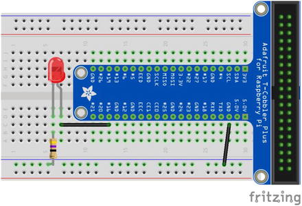 Figure 4-3
Circuit layout for the LED example
- 2.
Connect the 220Ω resistor between the ground rail and an empty 5-hole rail.
- 3.Connect the LED cathode to the same rail as the resistor. The cathode is the pin closest to the flat side of the LED. On some LEDs, this pin is shorter than the other pin (see Figure 4-4).
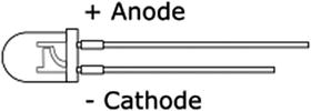 Figure 4-4
LED polarity
- 4.
Connect the LED anode to another empty 5-pin rail.
- 5.
Connect a jumper from the anode’s rail to the rail connected to pin 16 on the T-Cobbler.
- 6.
Connect a jumper from the ground rail that the LED is connected to and a rail connected to any of the ground pins of the T-Cobbler.
If you want to test the LED before moving on to the code, you can move the jumper from pin 16 to one of the 3.3V pins. If your Pi is powered on, the LED will illuminate. Make sure that you move the jumper back to pin 16 before continuing.
Writing the Code
The code for this project is very simple. It is written in Python 3. Although the code works in either version, one of the lines will not work in Python 2.7. Specifically, the print line at the end uses the end parameter, which is not compatible. If you are using Python 2.7, you will need to omit this parameter.
The end parameter replaces the default /n that is appended to each printed line, with a /r. The /r is a carriage return as opposed to the new line represented by /n. This means that the cursor returns to the beginning of the current line, and any new text overwrites the pervious characters. It does not clear the line first, however. So we append an arbitrary number of empty spaces to the end of the new text to ensure that all the previous text is completely removed.
The GPIO commands access system–level memory. All system-level commands must run with super user or root access. This means that you need to run Python with sudo or grant yourself permanent root permissions, which can be dangerous. Once we’ve written the code, we will execute in from the command. We have to make the file executable before we do this, but that is simple to do from the terminal.
To start, let’s create a new Python 3 file by using IDLE or on the terminal.
- 1.
Open IDLE for Python 3.
- 2.
Click New.
- 3.
Save the file as gpio_led.py in your project folder.
- 1.
Open the terminal window.
- 2.
Navigate to your project folder. On my Pi, it is
$ cd ~/TRG-RasPi-Robot/code
- 3.
Type touch gpio_led.py.
- 4.
Type idle3 gpio_led.py.
This opens the empty file in the IDLE IDE for Python 3.
- 5.
Once your file is created and you are in the IDLE editor, enter the following code:
# GPIO example blinking LED# Import the GPIO and time librariesimport RPi.GPIO as GPIOimport time# Set the GPIO mode to BCM and disable warningsGPIO.setmode(GPIO.BCM)GPIO.setwarnings(False)# Define pinsled = 16GPIO.setup(led,GPIO.OUT)# Make sure LED is offGPIO.output(led,False)# Begin Loopwhile True:# Turn LED onGPIO.output(led,True)# Wait 1 secondtime.sleep(1)# Turn LED offGPIO.output(led,False)# Wait 1 secondtime.sleep(1) - 6.
Save the file.
- 1.
Open a new terminal window and navigate to your project folder.
- 2.
Type chmod +x gpio_led.py.
This makes the file executable.
- 3.
To run the code, type sudo python3 gpio_led.py.
There you have it: a blinking LED. Hello world.
Pulse Width Modulation (PWM)
Even though there are only two PWM pins on the Pi’s GPIO header, and you likely won’t use them, it is useful to know how to control them properly. The two PWM pins on the board are 18 and 19. For this example, we’ll set up the LED to use pin 18 and pulse the LED.
Hooking Up the Circuit
- 1.
Move the jumper from pin 16 to pin 18.
Phew. Now that we’ve gotten through all of that, let’s code.
Writing the Code
Create a new Python 3 file.
- 1.
Open IDLE for Python 3.
- 2.
Click New.
- 3.
Save the file as gpio_pwm_led.py in your project folder.
- 1.
In the terminal window, navigate to your project folder. On my Pi, it is
$ cd ~/TRG-RasPi-Robot/code.
- 2.
Type touch gpio_pwm_led.py.
- 3.
Type idle3 gpio_pwm_led.py.
This opens the empty file in the IDLE IDE for Python 3.
- 4.
Once your file is created and you are in the IDLE editor, enter the following code:
# GPIO example blinking LED# Import the GPIO and time librariesimport RPi.GPIO as GPIOimport time# Set the GPIO mode to BCM and disable warningsGPIO.setmode(GPIO.BCM)GPIO.setwarnings(False)# Define pinspwmPin = 18GPIO.setup(pwmPin,GPIO.OUT)pwm = GPIO.PWM(pwmPin,100)# Make sure LED is offpwm.start(0)# Begin Loopwhile True:count = 1# begin while loop to brighten LEDwhile count < 100:# set duty cyclepwm.ChangeDutyCycle(count)# delay 1/100 of a secondtime.sleep(0.01)# increment countcount = count + 1# begin while loop to dim LEDwhile count > 1:pwm.ChangeDutyCycle(count)time.sleep(0.01)# set duty cyclepwm.ChangeDutyCycle(count)# delay 1/100 of a secondtime.sleep(0.01)# decrement countcount = count – 1 - 5.
Open a new terminal window and navigate to your project folder.
- 6.
Type chmod +x gpio_pwm_led.py to make the file executable.
- 7.
To run the code, type
sudo python3 gpio_pwm_led.py
Your LED should now be pulsing. To change the rate at which it pulses, change the value in the time.sleep() function calls.
Simple Input
Now that we’ve seen how easy it is to send out a signal, it’s time to get some information back into the Pi. We’ll do this through two examples. First, the push-button; in this example, the Pi is set up to take input from a simple push-button and indicate in the terminal when the button has been pushed. The second example uses a sonic rangefinder to read the distance to an object. The output will be displayed in the terminal.
Push-button Example
The simplest form of input is a push-button. You press a button, the circuit closes, and something happens. For our first input example, we will connect a push-button to the GPIO header.
There are essentially two ways to connect a push-button. You can set it up to start in a low state, which means that when the button is not pushed, there is no signal going to the pin, and the voltage on the pin is read as “low” by the processor. You can also connect it in a high state. In this configuration, the pin reads as high, or on, when the button is not pushed. When the button is pushed, the pin is brought to the low state.
You frequently hear the terms pulling high or pulling low. Pulling a pin high or low is the method that forces the pin into a high or a low state. In many applications, this is done by adding a resistor to the circuit.
A resistor connected between the logic pin and the voltage causes the pin to be in a high state. The pin is pulled high. The button is then connected to ground. When the button is pushed, the voltage flows through the button to ground, bypassing the pin. With no voltage going to the pin, it goes into a low state.
Conversely, connecting the resistor between the logic pin and ground, and then connecting the button between the pin and the voltage source, the pin is pulled down. While the button is open, any residual voltage in the pin is drawn to ground, leaving the pin in a low state. When the button is pushed, voltage is applied to the pin and it goes into a high state.
Pins are pulled high or low to assure that they are in the expected state when the button is pushed. It’s a way to explicitly tell the circuit how it is expected to behave, and it’s generally a good practice.
Fortunately, the Raspberry Pi has built-in circuitry to accommodate pulling a pin high or low. This means that we can pull a pin to the proper state through code, and we don’t have to worry about adding extra components.
For this exercise, let’s pull the pin high. When the button is pushed, the pin goes low and a message prints to the terminal window.
Hooking up the Circuit
Tactile push-button switch
4 male-to-male jumpers
- 1.Attach the T-Cobbler as shown in Figure 4-5. One row of pins should be on either side of the split in the board. The placement is up to you; however, I generally attach it so that the ribbon cable header is off the board. This allows maximum access to the breadboard.
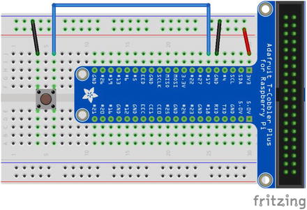 Figure 4-5
Push-button example circuit layout
- 2.
Connect a tactile push-button so that the pins bridge the gap in the center of the breadboard.
- 3.
Connect a jumper between the 3.3V pin and the voltage rail.
- 4.
Connect another jumper between the ground pin and the ground rail.
- 5.
Use another jumper to connect one side of the tactile switch to the ground rail.
- 6.
Use the remaining jumper to connect the other button pin to pin 17.
These tactile switches are double pole, single throw (DPST). This means that when the button is pushed, the two pins on one side of the breadboard gap are connected. The pins on the other side of the gap form a separate circuit. Be sure that the jumpers are going to pins on the same side of the divide.
Writing the Code
Create a new Python 3 file.
- 1.
Open IDLE for Python 3.
- 2.
Click New.
- 3.
Save the file as gpio_button.py in your project folder.
- 1.
Navigate to your project folder. On my Pi it is
$ cd ~/TRG-RasPi-Robot/code.
- 2.
Type touch gpio_button.py.
- 3.
Type idle3 gpio_button.py. This opens the empty file in the IDLE IDE for Python 3.
- 4.
Enter the following code:
# GPIO example using an NC-SR04 ultrasonic rangefinder# import the GPIO and time librariesimport RPi.GPIO as GPIO# Set the GPIO mode to BCM mode and disable warningsGPIO.setmode(GPIO.BCM)GPIO.setwarnings(False)# Define pinbtnPin = 20GPIO.setup(btnPin, GPIO.IN, pull_up_down = GPIO.PUD_UP)# Begin while loopwhile True:btnVal = GPIO.input(btnPin)# If the pin is low, print to terminalif (btnVal == false):print('Button pressed') - 5.
Open a new terminal window and navigate to your project folder.
- 6.
Type chmod +x gpio_button.py.
- 7.
To run the code, type
sudo python3 gpio_button.py
Sonic Rangefinder Example
For this example, let’s use the HC-SR04 ultrasonic sensor to determine the distance to an object. You’ll put the call into a loop that allows us to get constant distance readings. You’ll use the libraries used in the previous example to access the GPIO pins.
This exercise introduces you to one of the key factors to watch out for with the Pi and many other devices: voltage difference between the sensors and the pins. Many sensors are designed to work at 5 volts. The Pi, however, uses 3.3 volts in its logic. That means all of the I/O pins are designed to work with 3.3 volts. Applying a 5V signal to any of these pins can cause severe damage to your Pi. The Pi does provide a few 5V source pins, but we need to reduce the returning signal to 3.3 volts.
Hooking Up the Circuit
This time, the circuit is a bit more complicated. Really. Keep in mind that the sensor works on 5 volts. The Pi’s GPIO pins work on 3.3 volts. Feeding a 5V return signal into a 3.3V pin can damage the Pi. To keep that from happening, let’s add a simple voltage divider to the echo pin.


HC-SR04
1kΩ resistor
2kΩ resistor
You can use two 1kΩ resistors in series, or a more popular, similar resistor is the 2.2kΩ. That’s what we’ll use.
4 male-to-female jumpers
4 male-to-male jumpers
- 1.Attach the T-Cobbler, as shown in Figure 4-6. One row of pins should be on either side of the split in the board. The placement is up to you; however, I generally attach it so that the ribbon cable header is off the board. This allows maximum access to the breadboard.
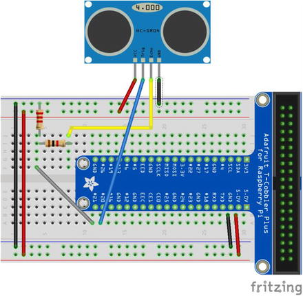 Figure 4-6
Sonic rangefinder example circuit layout
- 2.
Make sure that the ground jumper is secure between the ground pin and the ground rail.
- 3.
Add a jumper between one of the 5V pins and the power rail.
- 4.
Use a male-to-female jumper to connect the ground pin on the SR04 to the ground rail.
- 5.
Connect the VCC or 5V pin from the SR04 to the power rail.
- 6.
Connect the trig pin on the SR04 to pin 20 of the T-Cobbler.
- 7.
Connect the 2kΩ resistor from an empty 5-pin rail to the ground rail.
- 8.
Connect the 1kΩ resistor from the rail connected to the 2kΩ resistor to another empty 5-pin rail.
- 9.
Connect another jumper between the rail connected to the 2kΩ resistor and pin 21 on the T-Cobbler.
- 10.
Connect the SR04 echo pin to the rail that the other end of the 1kΩ resistor is connected to.
That completes the wiring. Now let’s get the code set up.
Writing the Code
The HC-SR04 ultrasonic rangefinder works by measuring the time it takes for an ultrasonic pulse to return to the sensor. We’ll send out a 10-microsecond pulse and then listen for the pulse to return. By measuring the length of the returned pulse, we can use a little math to calculate the distance in centimeters.
Distance is calculated as speed × time. It’s derived from the formula speed = distance ÷ time. At sea level, sound travels at a rate of 343m per second, or 34,300cm per second. Since we are actually measuring the time it takes for the pulse to reach its target and return, we really only need half of that value. Let’s working with the following formula:
Distance = 17,150 × time
The code simply sends out a 10μS pulse, measures the time it takes to return, calculates the estimated distance in centimeters, and displays it in the terminal window.
Create a new Python 3 file.
- 1.
Open IDLE for Python 3.
- 2.
Click New.
- 3.
Save the file as gpio_sr04.py in your project folder.
- 1.
Navigate to your project folder. On my Pi it is
$ cd ~/TRG-RasPi-Robot/code
- 2.
Type touch gpio_sr04.py.
- 3.
Type idle3 gpio_sr04.py. This opens the empty file in the IDLE IDE for Python 3.
- 4.
Enter the following code:
# GPIO example using an NC-SR04 ultrasonic rangefinder# import the GPIO and time librariesimport RPi.GPIO as GPIOimport time# Set the GPIO mode to BCM mode and disable warningsGPIO.setmode(GPIO.BCM)GPIO.setwarnings(False)# Define pinstrig = 20echo = 21GPIO.setup(trig,GPIO.OUT)GPIO.setup(echo,GPIO.IN)print("Measuring distance")# Begin while loopwhile True:# Set trigger pin low got 1/10 secondGPIO.output(trig,False)time.sleep(0.1)# Send a 10uS pulseGPIO.output(trig,True)time.sleep(0.00001)GPIO.output(trig,False)# Get the start and end times of the return pulsewhile GPIO.input(echo)==0:pulse_start = time.time()while GPIO.input(echo)==1:pulse_end = time.time()pulse_duration = pulse_end - pulse_start# Calculate the distance in centimetersdistance = pulse_duration * 17150distance = round(distance, 2)# Display the results. end = ' ' forces the output to the same lineprint("Distance: " + str(distance) + "cm ", end = ' ') - 5.
Open a new terminal window and navigate to your project folder.
- 6.
Type chmod +x gpio_sr04.py.
- 7.
To run the code, type
sudo python3 gpio_sr04.py
Summary
One of the great things about the Raspberry Pi is the GPIO header. The 40-pin header allows you to interface directly with sensors and other devices. In addition to the simple GPIO we used to connect to the LED, button, and ultrasonic sensor, there are pins with other specific functions. I suggest exploring some of these other functions. Pins marked SCL, SDA, MISO, and MOSI are serial connections that allow you to use advanced sensors, such as accelerometers and GPS.
To run your script, first make the file executable by using chmod +x <filename>.
Whenever you are running scripts that use the GPIO pins, you need to use sudo.
Pay careful attention to the voltages used by your sensors.
Although the header can supply 5 volts for devices, the logic pins are 3.3 volts. You will damage your Raspberry Pi if you don’t reduce the signal coming from the sensor.
A voltage splitting circuit—like the one built for the ultrasonic sensor—can be used to reduce 5V signals from sensors to 3.3 volts.
Premade boards called logic level shifters reduce the voltage.
The Raspberry Pi has no functionally useful analog pins.
It has only two PWM channels. Each of these is connected to two pins, so it may look like it has four usable PWM pins, but it really doesn’t.
In the next chapter, we connect an Arduino board to our Raspberry Pi. The Arduino is a microcontroller designed for IO. That is all it does, but it does it well. By combining these two boards, we not only overcome the Pi’s shortcomings, but also add other benefits.