In the last chapter, we built the Adafruit Motor HAT, an electronic device that allows you to control up to four DC motors with your Raspberry Pi. We also looked at a generic motor controller that we ran through the Arduino board. Now that you know how to get your robot to move, let’s start building it.
In this chapter, we will build our robot. Along the way, I’ll give some tips and pointers I’ve picked up in my builds. There are a lot of little things to consider when assembling a robot. You’ll encounter some odd scenarios that you hadn’t considered. The most overlooked is wiring and wire management. Things like order of operations and component placement are very important. Decisions made early in a build can cause complications later. Being mindful of these things can help keep you from having to disassemble your robot to correct an error that you made early on.
The build is broken into four separate exercises. We’ll start by building the Whippersnapper chassis kit. Then we’ll mount the electronics, which is followed by the wiring. Finally, we’ll look at mounting the ultrasonic sensors. In each exercise, I’ll point out some of the things to consider when working on your own build.
Assembling the Chassis
For this build, I chose to use a commercially available kit. The nice thing about kits is that a good kit has everything you need to get started. There are many options at many different price points and from many different manufacturers. Many of the low-cost kits, generally found online from foreign sellers, are less complete than others. Often, these are kits for popular devices but are assembled with little thought on how the parts go together. So, if you’re going to buy a kit, make sure that it’s got all the hardware and that the parts are designed to work together.
Choosing a Material
The materials are another thing to consider when selecting a chassis. A metal chassis is good. It tends to be more costly than a plastic chassis, but it also tends to be a lot more durable. In terms of plastic kits, remember that not all plastics are the same.
Acrylic is an inexpensive and convenient material to use; however, it is not the right material for most applications. Acrylic is brittle, inflexible, and scratches easily. When it breaks, it usually does so in sharp pieces. It is also wise to remember not to use acrylic in any kind of high-friction application because it tends to breakdown into course granules that amplify the friction.
If you’re going to use plastics, ABS is a better material to use. Like acrylic, ABS comes in sheets and is fairly inexpensive. Unlike acrylic, it is much more durable. It doesn’t crack or break as easily, and it is more scratch resistant. ABS is drillable and easier to work with than acrylic is.
Another option is polystyrene. Styrene is the material used for plastic model kits. So, if you’re familiar with working with these kits, then styrene is an easy choice. It is more flexible than either acrylic or ABS. It tends to be a little more expensive than the others are, but it is easy to work with.
The Whippersnapper
The Whippersnapper is a commercial kit made with lasercut ABS sheets. It is part of the Runt Rover line from Actobotics, manufactured by ServoCity. I have worked with several kits from the Actobotics line, and I know them to be well-designed, quality products. In addition to the robot kits, they produce a broad line of parts that are designed to work together.
All of these things contributed to the selection of the Whippersnapper (see Figure 7-1) for the base of this project. It doesn’t hurt that it’s a good-looking chassis with space to hold all the electronics and leave some room to grow.

All the Whippersnapper parts
- 1.Attach the center support to one of the sides. Make sure that the course side is facing out. Take note of the tabs on the center support. The single pair of tabs attaches to the bottom plate (see Figure 7-2).
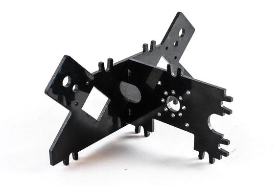 Figure 7-2
Center support attached to an outer plate
- 2.
Attach the second side plate to the center support. Again, make sure that the course side is on the outside of the robot.
- 3.Snap the top plate to the assembly. There are six sets of tabs that snap to the top plate (see Figure 7-3).
 Figure 7-3
Top plate added
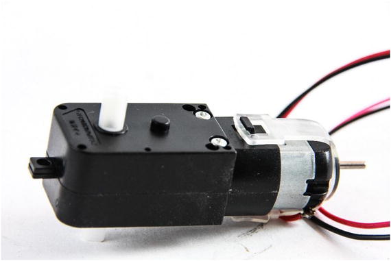
Motor with tab
- 1.
Mount the motor so that the shaft goes through the lower hole and the peg goes into the second one.
- 2.Use two screws and nuts to hold the motor in place (see Figure 7-5). Although not included in the kit, some #4 split lock washers would be good to use here. If you don’t have any, use Loctite Threadlocker Blue on the nuts. Without something to lock them into place, the nuts will rattle off.
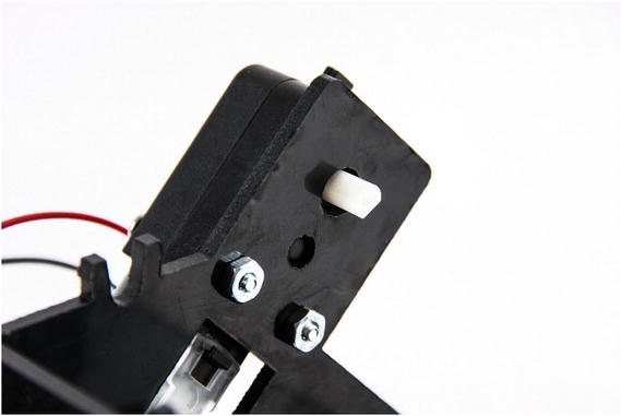 Figure 7-5
Mounted motor
- 3.Repeat the process for each of the three remaining motors (see Figure 7-6).
 Figure 7-6
All motors mounted
- 4.Flip the chassis over and attach the bottom plate. There are five sets of tabs holding the bottom plate on (see Figure 7-7).
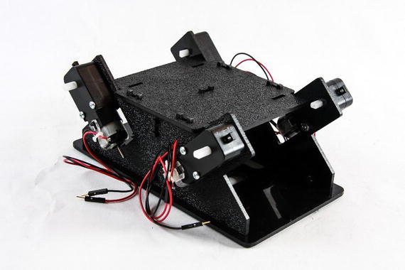 Figure 7-7
Bottom plate added
- 5.Feed the wires for each motor into the chassis through the hole behind the motor (see Figure 7-8). This bit of housekeeping keeps the wires from getting tangled in the wheels or caught onto something.
 Figure 7-8
Motor wires fed through the hole behind the motor
- 6.
Attach the electronics clips to the top plate. These clips will be used for holding the Raspberry Pi.
- 7.
Feed the wires for the front motors through the hole in the center support plate.

The completed Whippersnapper
Mounting the Electronics
Next, we’ll mount the electronics to the chassis. Starting with the Raspberry Pi, we’ll attach each component, with the Arduino and the breadboard mounted toward the front.
- 1.Snap the Raspberry Pi into the clips on the top plate (see Figure 7-10). The Pi should be held firmly in place by the top barbs.
 Figure 7-10
Raspberry Pi mounted in the clips
The tabs that hold the chassis together (see Figure 7-11) make mounting the Arduino and breadboard a challenge. This is one reason I like to use foam mounting tape—it provides some padding. To clear the tabs, we’ll need to double up on the tape. Figure 7-11
Clip protruding from the top plate
- 2.Stack two pieces of foam tape on top of each other and place them on the top plate. Use a second set of stacked foam tape to form a T (see Figure 7-12). This adds stability.
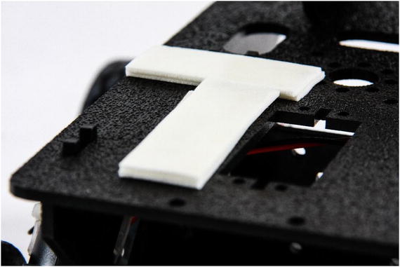 Figure 7-12
Double layer of mounting tape for the breadboard
- 3.Remove the protective paper from the bottom of the breadboard and press the breadboard firmly into the T-shaped tape on the top plate (see Figure 7-13).
 Figure 7-13
Mounted breadboard . Note that the T-cobbler has been moved forward to allow room for the power pack.
- 4.Repeat the procedure for the Arduino (see Figure 7-14).
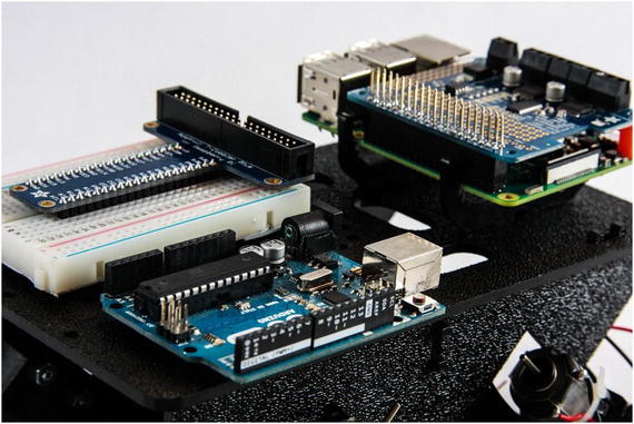 Figure 7-14
Arduino mounted on a double layer of mounting tape
When mounting the Arduino, remember to leave room for the USB cable. I offset the Arduino from the center so that the USB plug is clear of the Raspberry Pi (see Figure 7-15). Figure 7-15
Leaving clearance for the USB cable
- 5.
Mount the 4 AA battery holder inside the chassis in the back. Be sure to mount it in such a way that it allows access to the batteries and the power switch, if applicable. I used foam mounting tape to hold mine in place.
- 6.
Find a place to securely mount the 5V power bank. I find that the space between the breadboard and the Raspberry Pi works well for the small power banks that I use. Your placement will be determined by the form factor of your power bank.
With the electronics in place, it’s time to start wiring the parts together.
Wiring
It would be inappropriate to try to write this part as step-by-step instructions. How you wire your robot is entirely up to you. Each robot is different. Wiring is determined by component placement, the cables that you use, and personal preference. Instead, I’ll walk you through how I wired my robot and the thought process behind my decisions, and include considerations for your project.
I prefer to keep my cables a tidy as possible. Some people put little thought into how they run the wires. I’ve seen some tangled messes under the covers of some robots. It’s important to me to be able to access the parts easily, and this includes the wires and cables.
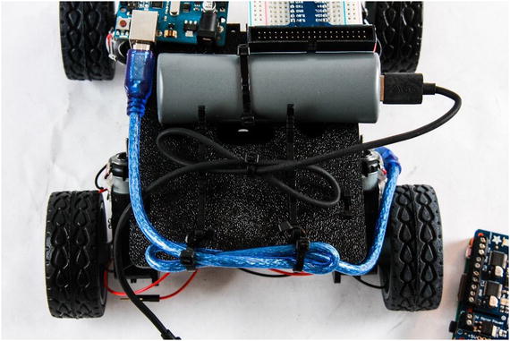
USB cables bundled for tidiness
Next, I connect the wires from the motors to the Motor HAT. The Motor HAT has four outputs for DC motors. There are four motors. I could attach the motors in pairs to two different outputs: one for the left side and one for the right; however, the small, inexpensive motors tend not to be very consistent in speed. Even though two motors receive the same signal, there is no guarantee that they will turn at the same rate. Being able to adjust the speed of each motor independently is a nice feature that I take advantage of. So, each motor has its own output (see Figure 7-17).

Motor and external battery pack wires connected to the Motor HAT
Once the motors are connected, I connect the power. When you connect yours, pay attention to the polarity. As a standard, red is positive and black is negative. Since my battery pack is modified, the wires are not red and black. I used a voltmeter to determine the polarity of the wires and connect them appropriately.

Ribbon cable attaches the T-cobbler to the Pi. Note the white stripe .
Mounting Sensors
This is where assembling the robot takes the most creativity. Most chassis do not come with mounting hardware for sensors. If they do, they are for specific sensors that you may not use.
There are a lot of different approaches for mounting sensors. I find simply being prepared with a number of different materials tends to work well for me.
When I was growing up, I had an Erector Set . If you’re not familiar with Erector, they produce a construction toy that includes a number of metal parts: beams, brackets, screws, nuts, pulleys, belts, and so forth. I spent hours building trucks, tractors, planes, and yes, even in the 1980s, robots. Imagine my delight when looking for some generic parts for use in a project, I came across an Erector Set in my local hobby store. I was even more delighted when I discovered that one of the local big-box hardware stores sells individual parts in their miscellaneous parts bins.
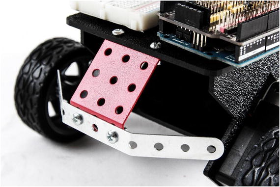
A bracket and beam from the Erector Set. The beam is bent to provide angles for the sensors.
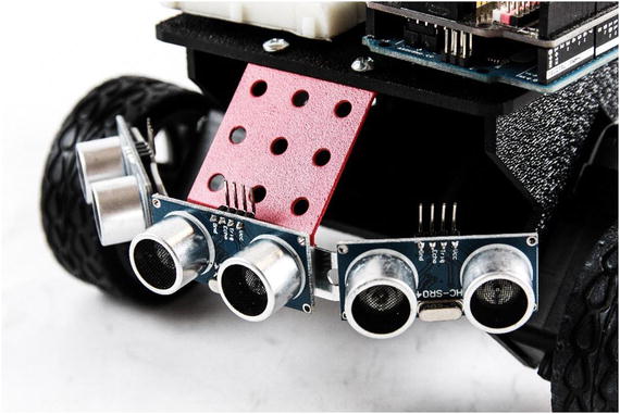
Ultrasonic sensors mounted
One thing I have learned is not to trust mounting tape alone for holding sensors, especially to metal. In the past, the tape has come loose, leading to a faulty sensor. The solution is my other favorite go-to: zip ties. The tape holds the sensor in place and provides insulation; however, the zip ties add security and strength. At this point, I’m pretty sure that things aren’t going anywhere.

Ultrasonic rangefinders secured with zip ties and wired to Arduino
The Finished Robot
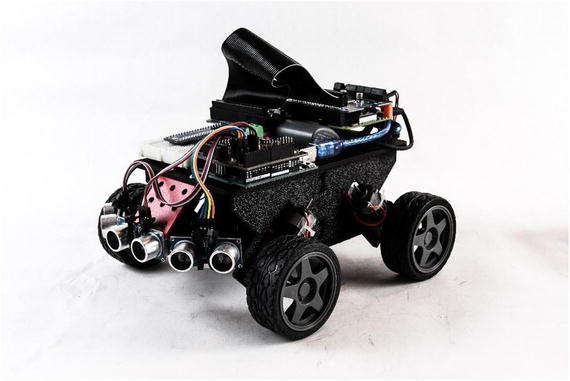
The finished Whippersnapper with electronics
Making the Robot Mobile
At the moment, we have a very nice collection of parts. Without the proper software, we don’t really have a robot. Next, I outline what we want the robot to do. We’ll turn that into behaviors, and those, in turn, into the code needed to bring the little robot to life.
The Plan
In previous chapters, we worked with examples that illustrated various topics. Since this is our first application for the working robot, let’s take a moment to outline what we want the robot to do.
This plan is based on the robot that I built earlier in this chapter. It assumes that there are three ultrasonic sensors and four motors that operate independently. The motors are controlled through the Motor HAT mounted on the Pi. The sensors are operated through the Arduino.
Sensors
As mentioned, we will operate three ultrasonic sensors. The sensors are connected to the Arduino through a sensor shield. Since we are using serial to communicate with the Pi, we cannot use pins 0 and 1. These are the pins used by the serial port. So, our first sensor, the middle, is on pins 2 and 3; the left sensor is on pins 4 and 5; and the right sensor is on pins 6 and 7.
The sensors are triggered in sequence, starting with the middle, followed by the left, and then the right. Each sensor waits until the previous one is done before triggering. The results are sent back to the Pi in half-second intervals as a string of floats representing the distance from each sensor in centimeters.
Motors
The motors are connected to the Motor HAT on the Raspberry Pi. Each motor is connected to one of the four motor channels on the controller. Motor 1, the front left motor, is connected to M1. Motor 2, the back left motor, is connected to M2. Motor 3, the front right motor, is on M3. And, motor 4, the back right motor, is on M4.
The robot drives using differential steering, also called tank drive or skid steering . To do this, the left motors drive together and the right ones drive together. I refer to them as left and right channels. So, the same commands are sent to M1 and M2. Likewise, M3 and M4 receive shared commands.
The code has multipliers for each motor. The multipliers are applied to each respective motor to compensate for differences in speed. The implication is that we need to allow a buffer to accommodate this difference. So, the top speed is set to a value of 200 out of 255. Initially, the multipliers are set to 1. You need to adjust your multipliers to fit your robot.
Behavior
The robot is a simple random roamer. It drives in a straight line until it detects an obstacle. It then adjusts its course to avoid striking the obstacle. This is not intended to be a particularly sophisticated solution, but it illustrates some basics in robot operation.
It drives forward.
If it detects an object to its left, it turns right.
If it detects an object to its right, it turns left.
If it detects an object directly in front of it, it stops and turns in the direction with the largest distance available.
If both directions have an equal distance, or both side sensors are beyond the cutoff value, the robot turns in a random direction for a predetermined time before continuing.
This behavior is somewhat basic, but it should provide a robot that wanders about the house autonomously.
The Code
The code is broken into two parts: for the Arduino and for the Pi. On the Arduino, all we care about is operating the sensors and relaying the readings back to the Pi at a predetermined interval. In this case, every 500 milliseconds, or half a second.
The Raspberry Pi uses the incoming data to execute the behavior. It reads from the serial port and parses the data into variables. These variables are used by the Pi to determine the next course of action. This action is translated into instructions for the motors, which are then sent to the motor controller to execute.
Arduino Code
- 1.
Open a new sketch in the Arduino IDE.
- 2.
Save the sketch as robot_sensors.
- 3.
Enter the following code:
int trigMid = 2;int echoMid = 3;int trigLeft = 4;int echoLeft = 5;int trigRight = 6;int echoRight = 7;float distMid = 0.0;float distLeft = 0.0;float distRight = 0.0;String serialString;void setup() {// set the pinModes for the sensorspinMode(trigMid, OUTPUT);pinMode(echoMid, INPUT);pinMode(trigLeft, OUTPUT);pinMode(echoLeft, INPUT);pinMode(trigRight, OUTPUT);pinMode(echoRight, INPUT);// set trig pins to low;digitalWrite(trigMid,LOW);digitalWrite(trigLeft,LOW);digitalWrite(trigRight,LOW);// starting serialSerial.begin(115200);}// function to operate the sensors// returns distance in centimetersfloat ping(int trigPin, int echoPin){// Private variables, not available// outside the functionint duration = 0;float distance = 0.0;// operate sensordigitalWrite(trigPin, HIGH);delayMicroseconds(10);digitalWrite(trigPin, LOW);// get results and calculate distanceduration = pulseIn(echoPin, HIGH);distance = duration/58.2;// return the resultsreturn distance;}void loop() {// get the distance for each sensordistMid = ping(trigMid, echoMid);distLeft = ping(trigLeft, echoLeft);distRight = ping(trigRight, echoRight);// write the results to the serial portSerial.print(distMid); Serial.print(",");Serial.print(distLeft); Serial.print(",");Serial.println(distRight);// wait 500 milliseconds before loopingdelay(500);} - 4.
Save the sketch and upload it to the Arduino.
The Arduino should now be pinging away, but since there is nothing listening, we don’t really know yet. Next, we’ll write the code for the Raspberry Pi.
Raspberry Pi Code
- 1.
Open IDLE for Python 2.7. Remember, the Adafruit library does not work yet in Python 3.
- 2.
Create a new file.
- 3.
Save it as pi_roamer_01.py.
- 4.
Enter the following code. I step through each portion to make sure that you have a solid idea of what is happening along the way.
- 5.
Import the libraries that you need.
import serialimport timeimport randomfrom Adafruit_MotorHAT import Adafruit_MotorHAT as amhatfrom Adafruit_MotorHAT import Adafruit_DCMotor as adamo - 6.
Create the motor variables and open the serial port. The Arduino is set up to run at a higher baud rate, so the Pi also needs to run at a higher baud.
# create motor objectsmotHAT = amhat(addr=0x60)mot1 = motHAT.getMotor(1)mot2 = motHAT.getMotor(2)mot3 = motHAT.getMotor(3)mot4 = motHAT.getMotor(4)# open serial portser = serial.Serial('/dev/ttyACM0', 115200) - 7.
Create the variables needed. Many of them are floats because we are working with decimals.
# create variables# sensorsdistMid = 0.0distLeft = 0.0distRight = 0.0# motor multipliersm1Mult = 1.0m2Mult = 1.0m3Mult = 1.0m4Mult = 1.0# distance thresholddistThresh = 12.0distCutOff = 30.0 - 8.
Set up the variables needed to manage the motors.
You’ll note that I have created a number of default values, and then assigned those values to other variables. The leftSpeed, rightSpeed, and driveTime variables should be the only ones that we actually change in code. The rest are to provide consistency throughout the program. If you want to change the default speed, you can simply change speedDef, and the change is applied everywhere.
# speedsspeedDef = 200leftSpeed = speedDefrightSpeed = speedDefturnTime = 1.0defTime = 0.1driveTime = defTime - 9.
Create the drive function. It is called from two places within the main body of the program. Because there is a lot of work involved, it is better to breakout the code into a separate function block.
def driveMotors(leftChnl = speedDef, rightChnl = speedDef, duration = defTime):# determine the speed of each motor by multiplying# the channel by the motors multiplierm1Speed = leftChnl * m1Multm2Speed = leftChnl * m2Multm3Speed = rightChnl * m3Multm4Speed = rightChnl * m4Mult# set each motor speed. Since the speed can be a# negative number, we take the absolute valuemot1.setSpeed(abs(int(m1Speed)))mot2.setSpeed(abs(int(m2Speed)))mot3.setSpeed(abs(int(m3Speed)))mot4.setSpeed(abs(int(m4Speed)))# run the motors. if the channel is negative, run# reverse. else run forwardif(leftChnl < 0):mot1.run(amhat.BACKWARD)mot2.run(amhat.BACKWARD)else:mot1.run(amhat.FORWARD)mot2.run(amhat.FORWARD)if (rightChnl > 0):mot3.run(amhat.BACKWARD)mot4.run(amhat.BACKWARD)else:mot3.run(amhat.FORWARD)mot4.run(amhat.FORWARD)# wait for durationtime.sleep(duration) - 10.
Begin the main block of the program by wrapping the code in a try block. This allows us to cleanly exit the program. Without it and the corresponding except block, the motors would continue to execute the last command they received.
try:while 1: - 11.
Continue the main block by reading the serial port and parsing the received string
# read the serial portval = ser.readline().decode('utf=8')print val# parse the serial stringparsed = val.split(',')parsed = [x.rstrip() for x in parsed]# only assign new values if there are# three or more availableif(len(parsed)>2):distMid = float(parsed[0] + str(0))distLeft = float(parsed[1] + str(0))distRight = float(parsed[2] + str(0)) - 12.
Enter the logic code. This is the code that executes the behavior outlined earlier.
Note that the midsensor block (the one that executes a stop and turn) is written outside the left and right obstacle avoidance code.
This is done because we want this logic to be evaluated regardless of the outcome of the left and right code. By including it after the other code, the midcode overwrites any of the values that the left/right code created.
# apply cutoff distanceif(distMid > distCutOff):distMid = distCutOffif(distLeft > distCutOff):distLeft = distCutOffif(distRight > distCutOff):distRight = distCutOff# reset driveTimedriveTime = defTime# if obstacle to left, steer right by increasing# leftSpeed and running rightSpeed negative defSpeed# if obstacle to right, steer to left by increasing# rightSpeed and running leftSpeed negativeif(distLeft <= distThresh):leftSpeed = speedDefrightSpeed = -speedDefelif (distRight <= distThresh):leftSpeed = -speedDefrightSpeed = speedDefelse:leftSpeed = speedDefrightSpeed = speedDef# if obstacle dead ahead, stop then turn toward most# open direction. if both directions open, turn randomif(distMid <= distThresh):# stopleftSpeed = 0rightSpeed = 0driveMotors(leftSpeed, rightSpeed, 1)time.sleep(1)leftSpeed = -150rightSpeed = -150driveMotors(leftSpeed, rightSpeed, 1)# determine preferred direction. if distLeft ># distRight, turn left. if distRight > distLeft,# turn right. if equal, turn randomdirPref = distRight - distLeftif(dirPref == 0):dirPref = random.random()if(dirPref < 0):leftSpeed = -speedDefrightSpeed = speedDefelif(dirPref > 0):leftSpeed = speedDefrightSpeed = -speedDefdriveTime = turnTime - 13.
Call the driveMotors function that we created earlier.
# drive the motorsdriveMotors(leftSpeed, rightSpeed, driveTime) - 14.
Flush any bytes still in the serial buffer.
ser.flushInput() - 15.
Enter the except block. It allows us to shut off the motors when we click Ctrl-C before we exit the program.
except KeyboardInterrupt:mot1.run(amhat.RELEASE)mot2.run(amhat.RELEASE)mot3.run(amhat.RELEASE)mot4.run(amhat.RELEASE) - 16.
Save the file.
- 17.
Press F5 to run the program.
When you’re done watching your little robot roam around the room, press Ctrl-C to end the program.
Congratulations. You’ve just built and programmed your first Raspberry Pi–powered robot.
We did a lot in this program—although there was really nothing that you hadn’t seen before. In the first part of the program, we imported the libraries that we need and created the motor objects. In the next section, we defined all of our variables. An important part of the program is the function that we created after the variables. In this function we drive the motors. The motor speeds and drive time are passed as parameters of the function which are used to set the speed of each motor. We use the sign of the speed to determine the motor direction. After that, we started our main block by wrapping it in a try block. We then entered the while loop, which allows the program to repeat indefinitely.
Within the while loop, we start by reading the serial string, and then we parse it to extract the three float values. The algorithm for converting the string to a float is a little different from what we used to convert to an integer. More specifically, we did not have to divide the result by 10. Adding a 0 to the end of a decimal does not change the value, so we can use it as it is converted.
The distance measurements determine the robot’s next action. The if/elsif/else block evaluates the sensor values. If either the left or the right sensor detects an obstacle within the predefined threshold, the robot turns in the opposite direction. If there is no obstacle detected, the robot continues forward. A separate if block determines if an obstacle is directly in front of the robot. If there is an obstacle, the robot stops and then turns. It uses the left and right sensor values to determine which way to go. If a direction cannot be determined, the robot turns in a random direction.
All of this takes time , during which the Arduino is happily sending serial strings and filling the Pi’s buffer. These strings must be purged before continuing. We use the flushInput() method of the serial object to do this. This way, we are working with only the most recent information.
Finally, we use the except block to capture the keyboard interrupt command. When it is received, the motors are released, stopping them. Then the program exits.
Summary
This chapter was about bringing together everything we learned so far into a working robot. We assembled the robot chassis kit and mounted all the electronics. Once everything was mounted to the robot, we wrote a program to run the robot. It was a fairly simple roaming program. When you run it, your new robot should wander about the room with varied success, depending on how crowded with furniture the room is.
In the next chapters, we work on improving the robot—adding more sensors, improving the logic, and adding some higher-level functionality. Specifically, we’ll be adding a camera and learning how to use OpenCV to track colors and chase a ball.