Chapter 16
Drawing with Quartz and OpenGL
Every application we've built so far has been constructed from views and controls that are part of the UIKit framework. You can do a lot with the UIKit stock components, and a great many applications can be constructed using only these objects. Some applications, however, can't be fully realized without going beyond what the UIKit stock components offer.
Sometimes, an application needs to be able to do custom drawing. Fortunately, we have not one, but two separate libraries we can call on for our drawing needs:
- Quartz 2D, which is part of the Core Graphics framework
- OpenGL ES, which is a cross-platform graphics library
OpenGL ES is a slimmed-down version of another cross-platform graphic library called OpenGL. OpenGL ES is a subset of OpenGL, designed specifically for embedded systems (hence the letters ES), such as the iPhone, iPad, and iPod touch.
In this chapter, we'll explore these powerful graphics environments. We'll build sample applications in both, and give you a sense of which environment to use and when.
Two Views of a Graphical World
Although Quartz 2D and OpenGL ES overlap a lot in terms of what you can accomplish with them, there are distinct differences between them.
Quartz 2D is a set of functions, datatypes, and objects designed to let you draw directly into a view or an image in memory. Quartz 2D treats the view or image that is being drawn into as a virtual canvas. It follows what's called a painter's model, which is just a fancy way of saying that the drawing commands are applied in much the same way as paint is applied to a canvas.
If a painter paints an entire canvas red, and then paints the bottom half of the canvas blue, the canvas will be half red and half either blue or purple (blue if the paint is opaque; purple if the paint is semitransparent). Quartz 2D's virtual canvas works the same way. If you paint the whole view red, and then paint the bottom half of the view blue, you'll have a view that's half red and half either blue or purple, depending on whether the second drawing action was fully opaque or partially transparent. Each drawing action is applied to the canvas on top of any previous drawing actions.
On the other hand, OpenGL ES is implemented as a state machine. This concept is somewhat more difficult to grasp, because it doesn't resolve to a simple metaphor like painting on a virtual canvas. Instead of letting you take actions that directly impact a view, window, or image, OpenGL ES maintains a virtual three-dimensional world. As you add objects to that world, OpenGL ES keeps track of the state of all objects.
Instead of a virtual canvas, OpenGL ES gives you a virtual window into its world. You add objects to the world and define the location of your virtual window with respect to the world. OpenGL ES then draws what you can see through that window based on the way it is configured and where the various objects are in relation to each other. This concept is a bit abstract, but it will make more sense when we build our OpenGL ES drawing application later in this chapter.
Quartz 2D provides a variety of line, shape, and image drawing functions. Though easy to use, Quartz 2D is limited to two-dimensional drawing. Although many Quartz 2D functions do result in drawing that takes advantage of hardware acceleration, there is no guarantee that any particular action you take in Quartz 2D will be accelerated.
OpenGL ES, though considerably more complex and conceptually more difficult, offers a lot more power than Quartz 2D. It has tools for both two-dimensional and three-dimensional drawing, and is specifically designed to take full advantage of hardware acceleration. OpenGL ES is also extremely well suited to writing games and other complex, graphically intensive programs.
Now that you have a general idea of the two drawing libraries, let's try them out. We'll start with the basics of how Quartz 2D works, and then build a simple drawing application with it. Then we'll re-create the same application using OpenGL ES.
The Quartz 2D Approach to Drawing
When using Quartz 2D (Quartz for short), you'll usually add the drawing code to the view doing the drawing. For example, you might create a subclass of UIView and add Quartz function calls to that class's drawRect: method. The drawRect: method is part of the UIView class definition and is called every time a view needs to redraw itself. If you insert your Quartz code in drawRect:, that code will be called, and then the view will redraw itself.
Quartz 2D's Graphics Contexts
In Quartz, as in the rest of Core Graphics, drawing happens in a graphics context, usually referred to just as a context. Every view has an associated context. You retrieve the current context, use that context to make various Quartz drawing calls, and let the context worry about rendering your drawing onto the view.
This line of code retrieves the current context:
CGContextRef context = UIGraphicsGetCurrentContext();
NOTE: Notice that we're using Core Graphics C functions, rather than Objective-C objects, to do our drawing. Both Core Graphics and OpenGL are C-based APIs, so most of the code we write in this part of the chapter will consist of C function calls.
Once you've defined your graphics context, you can draw into it by passing the context to a variety of Core Graphics drawing functions. For example, this sequence will create a path consisting of a 4-pixel-wide line in the context, and then draw that line:
CGContextSetLineWidth(context, 4.0);

CGContextSetStrokeColorWithColor(context, [UIColor redColor].CGColor);

CGContextMoveToPoint(context, 10.0f, 10.0f);

CGContextAddLineToPoint(context, 20.0f, 20.0f);

CGContextStrokePath(context);
The first call specifies that lines used to create the current path should be drawn 4 pixels wide. Think of this as selecting the size of the brush you're about to paint with. Until you call this function again with a different number, all lines will have a width of four lines when drawn. We then specify that the stroke color should be red. In Core Graphics, two colors are associated with drawing actions:
- The stroke color is used in drawing lines and for the outline of shapes.
- The fill color is used to fill in shapes.
A context has a sort of invisible pen associated with it that does the line drawing. As drawing commands are executed, the movements of this pen form a path. When you call CGContextMoveToPoint(), you move the end point of the current path to that location, without actually drawing anything. Whatever operation comes next, it will do its work relative to the point to which you moved the pen. In the earlier example, for instance, we first moved the pen to (10, 10). The next function call drew a line from the current pen location (10, 10) to the specified location (20, 20), which became the new pen location.
When you draw in Core Graphics, you're not drawing anything you can actually see. You're creating a path, which can be a shape, a line, or some other object, but it contains no color or other features to make it visible. It's like writing in invisible ink. Until you do something to make it visible, your path can't be seen. So, the next step is to tell Quartz to draw the line using CGContextStrokePath(). This function will use the line width and the stroke color we set earlier to actually color (or “paint”) the path and make it visible.
The Coordinate System
In the previous chunk of code, we passed a pair of floating-point numbers as parameters to CGContextMoveToPoint() and CGContextLineToPoint(). These numbers represent positions in the Core Graphics coordinate system. Locations in this coordinate system are denoted by their x and y coordinates, which we usually represent as (x, y). The upper-left corner of the context is (0, 0). As you move down, y increases. As you move to the right, x increases.
In the previous code snippet, we drew a diagonal line from (10, 10) to (20, 20), which would look like the one shown in Figure 16–1.
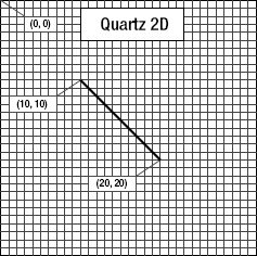
Figure 16–1. Drawing a line using Quartz 2D's coordinate system
The coordinate system is one of the gotchas in drawing with Quartz, because Quartz's coordinate system is flipped from what many graphics libraries use and from the traditional Cartesian coordinate system (introduced by René Descartes in the seventeenth century). In OpenGL ES, for example, (0, 0) is in the lower-left corner, and as the y coordinate increases, you move toward the top of the context or view, as shown in Figure 16–2. When working with OpenGL, you must translate the position from the view's coordinate system to OpenGL's coordinate system. That's easy enough to do, as you'll see when we work with OpenGL ES later in the chapter.
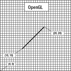
Figure 16–2. In many graphics libraries, including OpenGL, drawing from (10, 10) to (20, 20) would produce a line that looks like this instead of the line in Figure 16–1.
To specify a point in the coordinate system, some Quartz functions require two floating-point numbers as parameters. Other Quartz functions ask for the point to be embedded in a CGPoint, a struct that holds two floating-point values: x and y. To describe the size of a view or other object, Quartz uses CGSize, a struct that also holds two floating-point values: width and height. Quartz also declares a datatype called CGRect, which is used to define a rectangle in the coordinate system. A CGRect contains two elements: a CGPoint called origin, which identifies the top left of the rectangle, and a CGSize called size, which identifies the width and height of the rectangle.
Specifying Colors
An important part of drawing is color, so understanding the way colors work on iOS is critical. This is one of the areas where the UIKit does provide an Objective-C class: UIColor. You can't use a UIColor object directly in Core Graphic calls, but since UIColor is just a wrapper around CGColor (which is what the Core Graphic functions require), you can retrieve a CGColor reference from a UIColor instance by using its CGColor property, as we showed earlier, in this code snippet:
CGContextSetStrokeColorWithColor(context, [UIColor redColor].CGColor);
We created a UIColor instance using a convenience method called redColor, and then retrieved its CGColor property and passed that into the function.
A Bit of Color Theory for Your iOS Device's Display
In modern computer graphics, a common way to represent colors is to use four components: red, green, blue, and alpha. In Quartz, each of these values is represented as CGFloat (which is a 4-byte floating-point value, the same as float). These values should always contain a value between 0.0 and 1.0.
NOTE: A floating-point value that is expected to be in the range 0.0 to 1.0 is often referred to as a clamped floating-point variable, or sometimes just a clamp.
The red, green, and blue components are fairly easy to understand, as they represent the additive primary colors, or the RGB color model (see Figure 16–3). If you add together light of these three colors in equal proportions, the result will appear to the eye as either white or a shade of gray, depending on the intensity of the light mixed. Combining the three additive primaries in different proportions gives you a range of different colors, referred to as a gamut.
In grade school, you probably learned that the primary colors are red, yellow, and blue. These primaries, which are known as the historical subtractive primaries, or the RYB color model, have little application in modern color theory and are almost never used in computer graphics. The color gamut of the RYB color model is much more limited than the RGB color model, and it also doesn't lend itself easily to mathematical definition. As much as we hate to tell you that your wonderful third-grade art teacher, Mrs. Smedlee, was wrong about anything, well, in the context of computer graphics, she was. For our purposes, the primary colors are red, green, and blue, not red, yellow, and blue.

Figure 16–3. A simple representation of the additive primary colors that make up the RGB color model
In addition to red, green, and blue, both Quartz and OpenGL ES use another color component, called alpha, which represents how transparent a color is. When drawing one color on top of another color, alpha is used to determine the final color that is drawn. With an alpha of 1.0, the drawn color is 100% opaque and obscures any colors beneath it. With any value less than 1.0, the colors below will show through and mix with the color above. When an alpha component is used, the color model is sometimes referred to as the RGBA color model, although technically speaking, the alpha isn't really part of the color; it just defines how the color will interact with other colors when it is drawn.
Other Color Models
Although the RGB model is the most commonly used in computer graphics, it is not the only color model. Several others are in use, including the following:
- Hue, saturation, value (HSV)
- Hue, saturation, lightness (HSL)
- Cyan, magenta, yellow, key (CMYK), which is used in four-color offset printing
- Grayscale
To make matters even more confusing, there are different versions of some of these models, including several variants of the RGB color space.
Fortunately, for most operations, we don't need to worry about the color model that is being used. We can just pass CGColor from our UIColor object, and in most cases, Core Graphics will handle any necessary conversions. If you use UIColor or CGColor when working with OpenGL ES, it's important to keep in mind that they support other color models, because OpenGL ES requires colors to be specified in RGBA.
Color Convenience Methods
UIColor has a large number of convenience methods that return UIColor objects initialized to a specific color. In our previous code sample, we used the redColor method to initialize a color to red.
Fortunately, the UIColor instances created by most of these convenience methods all use the RGBA color model. The only exceptions are the predefined UIColors that represent grayscale values—such as blackColor, whiteColor, and darkGrayColor—which are defined only in terms of white level and alpha. In our examples here, we're not using those, so we can assume RGBA for now.
If you need more control over color, instead of using one of those convenience methods based on the name of the color, you can create a color by specifying all four of the components. Here's an example:
return [UIColor colorWithRed:1.0f green:0.0f blue:0.0f alpha:1.0f];
Drawing Images in Context
Quartz allows you to draw images directly into a context. This is another example of an Objective-C class (UIImage) that you can use as an alternative to working with a Core Graphics data structure (CGImage). The UIImage class contains methods to draw its image into the current context. You'll need to identify where the image should appear in the context using either of the following techniques:
- By specifying a
CGPointto identify the image's upper-left corner - By specifying a
CGRectto frame the image, resized to fit the frame, if necessary
You can draw a UIImage into the current context like so:
CGPoint drawPoint = CGPointMake(100.0f, 100.0f);

[image drawAtPoint:drawPoint];
Drawing Shapes: Polygons, Lines, and Curves
Quartz provides a number of functions to make it easier to create complex shapes. To draw a rectangle or a polygon, you don't need to calculate angles, draw lines, or do any math at all. You can just call a Quartz function to do the work for you. For example, to draw an ellipse, you define the rectangle into which the ellipse needs to fit and let Core Graphics do the work:
CGRect theRect = CGMakeRect(0,0,100,100);

CGContextAddEllipseInRect(context, theRect);

CGContextDrawPath(context, kCGPathFillStroke);
You use similar methods for rectangles. Quartz also provides methods that let you create more complex shapes, such as arcs and Bezier paths.
NOTE: We won't be working with complex shapes in this chapter's examples. To learn more about arcs and Bezier paths in Quartz, check out the Quartz 2D Programming Guide in the iOS Dev Center at http://developer.apple.com/documentation/GraphicsImaging/Conceptual/drawingwithquartz2d/ or in Xcode's online documentation.
Quartz 2D Tool Sampler: Patterns, Gradients, and Dash Patterns
Although not as expansive as OpenGL ES, Quartz does offer quite an impressive array of tools. For example, Quartz supports filling polygons with gradients, not just solid colors, and an assortment of dash patterns in addition to solid lines. Take a look at the screenshots in Figure 16–4, which are from Apple's QuartzDemo sample code, to see a sampling of what Quartz can do for you.
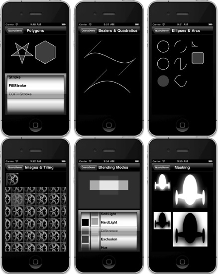
Figure 16–4. Some examples of what Quartz 2D can do, from the QuartzDemo sample project provided by Apple
Now that you have a basic understanding of how Quartz works and what it is capable of doing, let's try it out.
The QuartzFun Application
Our next application is a simple drawing program (see Figure 16–5). We're going to build this application twice: now using Quartz, and later using OpenGL ES. This will give you a real feel for the difference between the two environments.
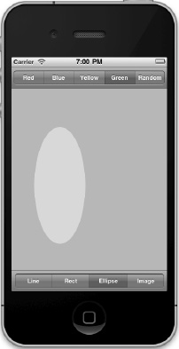
Figure 16–5. Our chapter's simple drawing application in action
The application features a bar across the top and one across the bottom, each with a segmented control. The control at the top lets you change the drawing color, and the one at the bottom lets you change the shape to be drawn. When you touch and drag, the selected shape will be drawn in the selected color. To minimize the application's complexity, only one shape will be drawn at a time.
Setting Up the QuartzFun Application
In Xcode, create a new iPhone project using the Single View Application template (with ARC but not using storyboards) and call it QuartzFun. The template has already provided us with an application delegate and a view controller. We're going to be executing our custom drawing in a custom view, so we need to also create a subclass of UIView where we'll do the drawing by overriding the drawRect: method.
With the QuartzFun folder selected (the folder that currently contains the app delegate and view controller files), press ![]() N to bring up the new file assistant, and then select Objective-C class from the Cocoa Touch section. Name the new class BIDQuartzFunView and make it a subclass of UIView.
N to bring up the new file assistant, and then select Objective-C class from the Cocoa Touch section. Name the new class BIDQuartzFunView and make it a subclass of UIView.
We're going to define some constants, as we've done in previous projects, but this time, our constants will be needed by more than one class. We'll create a header file just for the constants.
Select the QuartzFun group again and press ![]() N to bring up the new file assistant. Select the Header File template from the C and C++ heading, and name the file BIDConstants.h.
N to bring up the new file assistant. Select the Header File template from the C and C++ heading, and name the file BIDConstants.h.
We have two more files to go. If you look at Figure 16–5, you can see that we offer an option to select a random color. UIColor doesn't have a method to return a random color, so we'll need to write code to do that. We could put that code into our controller class, but because we're savvy Objective-C programmers, we'll put it into a category on UIColor.
Again, select the QuartzFun folder and press ![]() N to bring up the new file assistant. Select the Objective-C category from the Cocoa Touch heading and hit Next. When prompted, name the category BIDRandom and make it a Category on UIColor. Click Next, and save the file into your project folder.
N to bring up the new file assistant. Select the Objective-C category from the Cocoa Touch heading and hit Next. When prompted, name the category BIDRandom and make it a Category on UIColor. Click Next, and save the file into your project folder.
You should now have a new pair of files named UIColor+BIDRandom.h and UIColor+BIDRandom.m for your category.
Creating a Random Color
Let's tackle the category first. Add the following line to UIColor+BIDRandom.h:
#import <UIKit/UIKit.h>


@interface UIColor (BIDRandom)

+ (UIColor *)randomColor;

@end
Now, switch over to UIColor+BIDRandom.m, and add this code:
#import "UIColor+BIDRandom.h"


@implementation UIColor (BIDRandom)

+ (UIColor *)randomColor {

    static BOOL seeded = NO;

    if (!seeded) {

        seeded = YES;

        srandom(time(NULL));

    }

    CGFloat red = (CGFloat)random() / (CGFloat)RAND_MAX;

    CGFloat blue = (CGFloat)random() / (CGFloat)RAND_MAX;

    CGFloat green = (CGFloat)random() / (CGFloat)RAND_MAX;

    return [UIColor colorWithRed:red green:green blue:blue alpha:1.0f];

}

@end
This is fairly straightforward. We declare a static variable that tells us if this is the first time through the method. The first time this method is called during an application's run, we will seed the random-number generator. Doing this here means we don't need to rely on the application doing it somewhere else, and as a result, we can reuse this category in other iOS projects.
Once we've made sure the random-number generator is seeded, we generate three random CGFloats with a value between 0.0 and 1.0, and use those three values to create a new color. We set alpha to 1.0 so that all generated colors will be opaque.
Defining Application Constants
Next, we'll define constants for each of the options that the user can select using the segmented controllers. Single-click BIDConstants.h, and add the following code:
#ifndef QuartzFun_BIDConstants_h

#define QuartzFun_BIDConstants_h


typedef enum {

    kLineShape = 0,

    kRectShape,

    kEllipseShape,

    kImageShape

} ShapeType;


typedef enum {

    kRedColorTab = 0,

    kBlueColorTab,

    kYellowColorTab,

    kGreenColorTab,

    kRandomColorTab

} ColorTabIndex;


#define degreesToRadian(x) (M_PI * (x) / 180.0)


#endif
To make our code more readable, we've declared two enumeration types using typedef. One will represent the shape options available in our application; the other will represent the various color options available. The values these constants hold will correspond to segments on the two segmented controllers we'll create in our application.
NOTE: Just in case you haven't seen this form before, the purpose of the #ifndef compiler directive is to first test if QuartzFun_BIDConstants_h is defined and, if not, to define it. Why not just put in the #define? This way, if a .h file is included more than once, either directly or via other .h files, the directive won't be duplicated.
Implementing the QuartzFunView Skeleton
Since we're going to do our drawing in a subclass of UIView, let's set up that class with everything it needs except for the actual code to do the drawing, which we'll add later. Single-click BIDQuartzFunView.h, and add the following code:
#import <UIKit/UIKit.h>

#import "BIDConstants.h"


@interface BIDQuartzFunView : UIView

@property (nonatomic) CGPoint firstTouch;

@property (nonatomic) CGPoint lastTouch;

@property (strong, nonatomic) UIColor *currentColor;

@property (nonatomic) ShapeType shapeType;

@property (nonatomic, strong) UIImage *drawImage;

@property (nonatomic) BOOL useRandomColor;

@end
First, we import the BIDConstants.h header we just created so we can make use of our enumeration values. We then declare our properties. The first two will track the user's finger as it drags across the screen. We'll store the location where the user first touches the screen in firstTouch. We'll store the location of the user's finger while dragging and when the drag ends in lastTouch. Our drawing code will use these two variables to determine where to draw the requested shape.
Next, we define a color to hold the user's color selection and a ShapeType to keep track of the shape the user wants to draw. After that is a UIImage property that will hold the image to be drawn on the screen when the user selects the rightmost toolbar item on the bottom toolbar (see Figure 16–6). The last property is a Boolean that will be used to keep track of whether the user is requesting a random color.
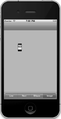
Figure 16–6. When drawing a UIImage to the screen, notice that the color control disappears. Can you tell which app is running on the tiny iPhone?
Switch to BIDQuartzFunView.m. We have several changes we need to make in this file. First, we're going to need access to the randomColor category method we wrote earlier in the chapter, at the top of the file. We'll also need to synthesize our properties. So add these lines directly below the existing import statement:
#import "UIColor+BIDRandom.h"


and add this one right after the @implementation declaration:


@synthesize firstTouch, lastTouch, currentColor, drawImage, useRandomColor, shapeType;
The template gave us a method called initWithFrame:, but we won't be using that. Keep in mind that object instances in nibs are stored as archived objects, which is the same mechanism we used in Chapter 13 to archive and load our objects to disk. As a result, when an object instance is loaded from a nib, neither init nor initWithFrame: is ever called. Instead, initWithCoder: is used, so this is where we need to add any initialization code. In our case, we'll set the initial color value to red, initialize useRandomColor to NO, and load the image file that we're going to draw later in the chapter. Delete the existing stub implementation of initWithFrame:, and replace it with the following method:
- (id)initWithCoder:(NSCoder*)coder {


    if (self = [super initWithCoder:coder]) {

        currentColor = [UIColor redColor];

        useRandomColor = NO;

        self.drawImage = [UIImage imageNamed:@"iphone.png"] ;

    }

    return self;

}
After initWithCoder:, we need to add a few more methods to respond to the user's touches. Insert the following three methods after initWithCoder:.
#pragma mark - Touch Handling


- (void)touchesBegan:(NSSet *)touches withEvent:(UIEvent *)event {

    if (useRandomColor) {

        self.currentColor = [UIColor randomColor];

    }

    UITouch *touch = [touches anyObject];

    firstTouch = [touch locationInView:self];

    lastTouch = [touch locationInView:self];

    [self setNeedsDisplay];

}


- (void)touchesEnded:(NSSet *)touches withEvent:(UIEvent *)event {

    UITouch *touch = [touches anyObject];

    lastTouch = [touch locationInView:self];


    [self setNeedsDisplay];

}


- (void)touchesMoved:(NSSet *)touches withEvent:(UIEvent *)event {

    UITouch *touch = [touches anyObject];

    lastTouch = [touch locationInView:self];


    [self setNeedsDisplay];

}
These three methods are inherited from UIView (but actually declared in UIView's parent UIResponder). They can be overridden to find out where the user is touching the screen. They work as follows:
touchesBegan:withEvent:is called when the user's finger first touches the screen. In that method, we change the color if the user has selected a random color using the newrandomColormethod we added toUIColorearlier. After that, we store the current location so that we know where the user first touched the screen, and we indicate that our view needs to be redrawn by callingsetNeedsDisplayonself.touchesMoved:withEvent:is continuously called while the user is dragging a finger on the screen. All we do here is store the new location inlastTouchand indicate that the screen needs to be redrawn.touchesEnded:withEvent:is called when the user lifts that finger off the screen. Just as in thetouchesMoved:withEvent:method, all we do is store the final location in thelastTouchvariable and indicate that the view needs to be redrawn.
Don't worry if you don't fully grok the rest of the code here. We'll get into the details of working with touches and the specifics of the touchesBegan:withEvent:, touchesMoved:withEvent:, and touchesEnded:withEvent: methods in Chapter 17.
We'll come back to this class once we have our application skeleton up and running. That drawRect: method, which is currently commented out, is where we will do this application's real work, and we haven't written that yet. Let's finish setting up the application before we add our drawing code.
Creating and Connecting Outlets and Actions
Before we can start drawing, we need to add the segmented controls to our nib, and then hook up the actions and outlets. Single-click BIDViewController.xib to edit the file.
The first order of business is to change the class of the view. Single-click the View icon in the dock and press ![]()
![]() 3 to bring up the identity inspector. Change the class from UIView to BIDQuartzFunView.
3 to bring up the identity inspector. Change the class from UIView to BIDQuartzFunView.
Select the newly renamed QuartzFunView icon and look for a Navigation Bar in the library. Make sure you are grabbing a Navigation Bar, not a Navigation Controller. We want the bar that goes at the top of the view. Place the navigation bar snugly against the top of the view, just beneath the status bar.
Next, look for a Segmented Control in the library, and drag that directly on top of the navigation bar. Drop it in the center of the navigation bar, not on the left or right side (see Figure 16–7).
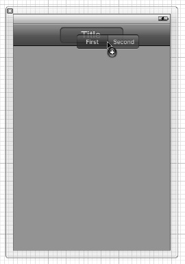
Figure 16–7. Dragging out a segmented control, being sure to drop it on top of the navigation bar
Once you drop the control, it should stay selected. Grab one of the resize dots on either side of the segmented control and resize it so that it takes up the entire width of the navigation bar. You don't get any blue guidelines, but Interface Builder won't let you make the bar any bigger than you want it in this case, so just drag until it won't expand any farther.
With the segmented control still selected, bring up the attributes inspector, and change the number of segments from 2 to 5. Double-click each segment in turn, changing its label to (from left to right) Red, Blue, Yellow, Green, and Random, in that order. At this point, your view should look like Figure 16–8.
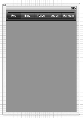
Figure 16–8. The completed navigation bar
Bring up the assistant editor, if it's not already open, and select BIDViewController.h from the jump bar. Now, control-drag from the segmented control in the dock to the BIDViewController.h file on the right. When your cursor is between the @interface and @end declarations, release the mouse to create a new outlet. Name the new outlet colorControl, and leave all the other options at their default values. Make sure you are dragging from the segmented control, not from the navigation bar or navigation item.
Next, let's add an action. Control-drag once again from the same segmented control over to the header file, directly above the @end declaration. This time, insert an action called changeColor:. The popup should default to using the Value Changed event, which is what we want.
Now, look for a Toolbar in the library (not a Navigation Bar), and drag one of those over, snug to the bottom of the view window. The toolbar from the library has a button on it that we don't need, so select the button and press the delete key on your keyboard. The button should disappear, leaving a blank toolbar in its stead.
With the toolbar in place, grab another Segmented Control, and drop it onto the toolbar (see Figure 16–9).
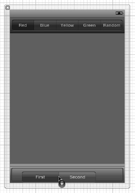
Figure 16–9. The view, showing a toolbar at the bottom of the window with a segmented control dropped onto the toolbar
As it turns out, segmented controls are a bit harder to center in a toolbar than in a navigation bar, so we'll bring in a little help. Drag a Flexible Space Bar Button Item from the library onto the toolbar, to the left of our segmented control. Next, drag a second Flexible Space Bar Button Item onto the toolbar, to the right of our segmented control (see Figure 16–10). These items will keep the segmented control centered in the toolbar as we resize it.
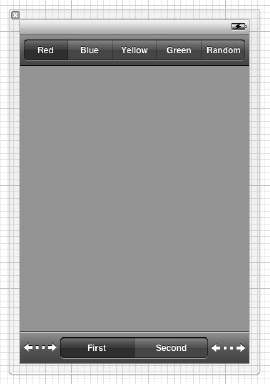
Figure 16–10. The segmented control after we dropped the Flexible Space Bar Button Item on either side. Note that we have not yet resized the segmented control to fill the toolbar.
It's time to resize the segmented control. In the dock, select the middle of the three Bar Button Items, the one with the Segmented Control as a subitem. A resize handle should appear on the left side of the segmented control in the editing area. Drag that handle to resize the segmented control, and resize it so it fills the toolbar, leaving just a bit of space to the left and right. Interface Builder won't give you guidelines or prevent you from making the segmented control wider than the toolbar, as it did with the navigation bar, so you'll need to be a little careful to resize the segmented control to the correct size.
Next, select the Segmented Control in the dock, bring up the attributes inspector, and change the number of segments from 2 to 4. Then double-click each segment and change the titles of the four segments to Line, Rect, Ellipse, and Image, in that order.
Once you've done that, be sure the Segmented Control is selected in the dock, and then control-drag from the segmented control over to BIDViewController.h to create another action. Change the connection type to Action, and name this new action changeShape:.
Our next task is to implement our action methods.
Implementing the Action Methods
Save the nib and feel free to close the assistant editor. Now, single-click BIDViewController.m. The first thing we need to do is to import our constants file so that we have access to our enumeration values. We'll also be interacting with our custom view, so we need to import its header as well. At the top of the file, immediately below the existing import statement, add the following lines of code:
#import "BIDConstants.h"

#import "BIDQuartzFunView.h"
Next, look for the stub implementation of changeColor: that Xcode created for you, and add the following code to it:
- (IBAction)changeColor:(id)sender {

    UISegmentedControl *control = sender;

    NSInteger index = [control selectedSegmentIndex];


    BIDQuartzFunView *quartzView = (BIDQuartzFunView *)self.view;


    switch (index) {

        case kRedColorTab:

            quartzView.currentColor = [UIColor redColor];

            quartzView.useRandomColor = NO;

            break;

        case kBlueColorTab:

            quartzView.currentColor = [UIColor blueColor];

            quartzView.useRandomColor = NO;

            break;

        case kYellowColorTab:

            quartzView.currentColor = [UIColor yellowColor];

            quartzView.useRandomColor = NO;

            break;

        case kGreenColorTab:

            quartzView.currentColor = [UIColor greenColor];

            quartzView.useRandomColor = NO;

            break;

        case kRandomColorTab:

            quartzView.useRandomColor = YES;

            break;

        default:

            break;

    }

}
This is pretty straightforward. We simply look at which segment was selected and create a new color based on that selection to serve as our current drawing color. In order to keep the compiler happy, we cast view, which is declared as an instance of UIView in our superclass, to QuartzFunView. After that, we set the currentColor property so that our class knows which color to use when drawing, except when a random color is selected. When a random color is chosen, it will look at the useRandomColor property, so we also set that to the appropriate value for each selection. Since all the drawing code will be in the view itself, we don't need to do anything else in this method.
Next, look for the existing implementation of changeShape:, and add the following code to it:
- (IBAction)changeShape:(id)sender {

    UISegmentedControl *control = sender;

    [(BIDQuartzFunView *)self.view setShapeType:[control

                                              selectedSegmentIndex]];


    if ([control selectedSegmentIndex] == kImageShape)

        colorControl.hidden = YES;

    else

        colorControl.hidden = NO;

}
In this method, all we do is set the shape type based on the selected segment of the control. Do you recall the ShapeType enum? The four elements of the enum correspond to the four toolbar segments at the bottom of the application view. We set the shape to be the same as the currently selected segment, and we hide and unhide the colorControl based on whether the Image segment was selected
NOTE: You may have wondered why we put a navigation bar at the top of the view and a toolbar at the bottom of the view. According to the Human Interface Guidelines published by Apple, navigation bars were specifically designed to be placed at the top of the screen and toolbars are designed for the bottom. If you read the descriptions of the Toolbar and Navigation Bar in Interface Builder's library window, you'll see this design intention spelled out.
Make sure that everything is in order by compiling and running your app. You won't be able to draw shapes on the screen yet, but the segmented controls should work, and when you tap the Image segment in the bottom control, the color controls should disappear.
Now that we have everything working, let's do some drawing.
Adding Quartz 2D Drawing Code
We're ready to add the code that does the drawing. We'll draw a line, some shapes, and an image. We're going to work incrementally, adding a small amount of code, and then running the app to see what that code does.
Drawing the Line
Let's do the simplest drawing option first: drawing a single line. Select BIDQuartzFunView.m, and replace the commented-out drawRect: method with this one:
- (void)drawRect:(CGRect)rect {

    CGContextRef context = UIGraphicsGetCurrentContext();


    CGContextSetLineWidth(context, 2.0);

    CGContextSetStrokeColorWithColor(context, currentColor.CGColor);


    switch (shapeType) {

        case kLineShape:

            CGContextMoveToPoint(context, firstTouch.x, firstTouch.y);

            CGContextAddLineToPoint(context, lastTouch.x, lastTouch.y);

            CGContextStrokePath(context);

            break;

        case kRectShape:

            break;

        case kEllipseShape:

            break;

        case kImageShape:

            break;

        default:

            break;

    }

}
We start things off by retrieving a reference to the current context so we know where to draw.
CGContextRef context = UIGraphicsGetCurrentContext();
Next, we set the line width to 2.0, which means that any line that we stroke will be 2 pixels wide.
CGContextSetLineWidth(context, 2.0);
After that, we set the color for stroking lines. Since UIColor has a CGColor property, which is what this method needs, we use that property of our currentColor property to pass the correct color on to this function.
CGContextSetStrokeColorWithColor(context, currentColor.CGColor);
We use a switch to jump to the appropriate code for each shape type. As we mentioned earlier, we'll start off with the code to handle kLineShape, get that working, and then we'll add code for each shape in turn as we make our way through this example.
    switch (shapeType) {

        case kLineShape:
To draw a line, we tell the graphics context to create a path starting at the first place the user touched. Remember that we stored that value in the touchesBegan: method, so it will always reflect the starting point of the most recent touch or drag.
CGContextMoveToPoint(context, firstTouch.x, firstTouch.y);
Next, we draw a line from that spot to the last spot the user touched. If the user's finger is still in contact with the screen, lastTouch contains Mr. Finger's current location. If the user is no longer touching the screen, lastTouch contains the location of the user's finger when it was lifted off the screen.
Then we stroke the path. This function will stroke the line we just drew using the color and width we set earlier:
CGContextStrokePath(context);
After that, we finish the switch statement.
           break;

       case kRectShape:

           break;

       case kEllipseShape:

           break;

       case kImageShape:

           break;

       default:

           break;

    }
And that's it for now. At this point, you should be able to compile and run the app once more. The Rect, Ellipse, and Shape options won't work, but you should be able to draw lines just fine using any of the color choices (see Figure 16–11).
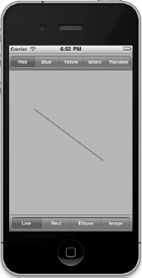
Figure 16–11. The line-drawing part of our application is now complete. Here, we are drawing using the color red.
Drawing the Rectangle and Ellipse
Let's write the code to draw the rectangle and the ellipse at the same time, since Quartz implements both of these objects in basically the same way. Add the following bold code to your existing drawRect: method:
- (void)drawRect:(CGRect)rect {

    CGContextRef context = UIGraphicsGetCurrentContext();


    CGContextSetLineWidth(context, 2.0);

    CGContextSetStrokeColorWithColor(context, currentColor.CGColor);


    CGContextSetFillColorWithColor(context, currentColor.CGColor);

    CGRect currentRect = CGRectMake(firstTouch.x,

                                    firstTouch.y,

                                    lastTouch.x - firstTouch.x,

                                    lastTouch.y - firstTouch.y);


    switch (shapeType) {

        case kLineShape:

            CGContextMoveToPoint(context, firstTouch.x, firstTouch.y);

            CGContextAddLineToPoint(context, lastTouch.x, lastTouch.y);

            CGContextStrokePath(context);

            break;

        case kRectShape:

            CGContextAddRect(context, currentRect);

            CGContextDrawPath(context, kCGPathFillStroke);

            break;

        case kEllipseShape:

            CGContextAddEllipseInRect(context, currentRect);

            CGContextDrawPath(context, kCGPathFillStroke);

            break;

        case kImageShape:

            break;

        default:

            break;

    }

}
Because we want to paint both the ellipse and the rectangle in a solid color, we add a call to set the fill color using currentColor.
CGContextSetFillColorWithColor(context, currentColor.CGColor);
Next, we declare a CGRect variable. We do this here because both the rectangle and ellipse are drawn based on a rect. We'll use currentRect to hold the rectangle described by the user's drag. Remember that a CGRect has two members: size and origin. A function called CGRectMake() lets us create a CGRect by specifying the x, y, width, and height values, so we use that to make our rectangle.
The code to create the rectangle is pretty straightforward. We use the point stored in firstTouch to create the origin. Then we figure out the size by getting the difference between the two x values and the two y values. Note that depending on the direction of the drag, one or both size values may end up with negative numbers, but that's OK. A CGRect with a negative size will simply be rendered in the opposite direction of its origin point (to the left for a negative width; upward for a negative height).
    CGRect currentRect = CGRectMake(firstTouch.x,

                                    firstTouch.y,

                                    lastTouch.x - firstTouch.x,

                                    lastTouch.y - firstTouch.y);
Once we have this rectangle defined, drawing either a rectangle or an ellipse is as easy as calling two functions: one to draw the rectangle or ellipse in the CGRect we defined, and the other to stroke and fill it.
        case kRectShape:

            CGContextAddRect(context, currentRect);

            CGContextDrawPath(context, kCGPathFillStroke);

            break;

        case kEllipseShape:

            CGContextAddEllipseInRect(context, currentRect);

            CGContextDrawPath(context, kCGPathFillStroke);

            break;
Compile and run your application. Try out the Rect and Ellipse tools to see how you like them. Don't forget to change colors, including using a random color.
Drawing the Image
For our last trick, let's draw an image. The 16 - QuartzFun folder contains an image named iphone.png that you can add to your Supporting Files folder, or you can use any .png file you prefer, as long as you remember to change the file name in your code to point to that image.
Add the following code to your drawRect: method:
- (void)drawRect:(CGRect)rect {


    CGContextRef context = UIGraphicsGetCurrentContext();


    CGContextSetLineWidth(context, 2.0);

    CGContextSetStrokeColorWithColor(context, currentColor.CGColor);


    CGContextSetFillColorWithColor(context, currentColor.CGColor);

    CGRect currentRect = CGRectMake(firstTouch.x,

                                    firstTouch.y,

                                    lastTouch.x - firstTouch.x,

                                    lastTouch.y - firstTouch.y);


    switch (shapeType) {

        case kLineShape:

            CGContextMoveToPoint(context, firstTouch.x, firstTouch.y);

            CGContextAddLineToPoint(context, lastTouch.x, lastTouch.y);

            CGContextStrokePath(context);

            break;

        case kRectShape:

            CGContextAddRect(context, currentRect);

            CGContextDrawPath(context, kCGPathFillStroke);

            break;

        case kEllipseShape:
            CGContextAddEllipseInRect(context, currentRect);

            CGContextDrawPath(context, kCGPathFillStroke);

            break;

        case kImageShape:{

            CGFloat horizontalOffset = drawImage.size.width / 2;

            CGFloat verticalOffset = drawImage.size.height / 2;

            CGPoint drawPoint = CGPointMake(lastTouch.x - horizontalOffset,

                                            lastTouch.y - verticalOffset);

            [drawImage drawAtPoint:drawPoint];

            break;

        }

        default:

            break;

    }

}
NOTE: Notice that in the switch statement, we added curly braces around the code under case kImageShape:. The compiler has a problem with variables declared in the first line after a case statement. These curly braces are our way of telling the compiler to stop complaining. We could also have declared horizontalOffset before the switch statement, but this approach keeps the related code together.
First, we calculate the center of the image, since we want the image drawn centered on the point where the user last touched. Without this adjustment, the image would be drawn with the upper-left corner at the user's finger, also a valid option. We then make a new CGPoint by subtracting these offsets from the x and y values in lastTouch.
CGFloat horizontalOffset = drawImage.size.width / 2;

CGFloat verticalOffset = drawImage.size.height / 2;

CGPoint drawPoint = CGPointMake(lastTouch.x - horizontalOffset,

                             lastTouch.y - verticalOffset);
Now, we tell the image to draw itself. This line of code will do the trick:
[drawImage drawAtPoint:drawPoint];
Optimizing the QuartzFun Application
Our application does what we want, but we should consider a bit of optimization. In our little application, you won't notice a slowdown, but in a more complex application, running on a slower processor, you might see some lag.
The problem occurs in BIDQuartzFunView.m, in the methods touchesMoved: and touchesEnded:. Both methods include this line of code:
[self setNeedsDisplay];
Obviously, this is how we tell our view that something has changed and it needs to redraw itself. This code works, but it causes the entire view to be erased and redrawn, even if only a tiny bit changed. We do want to erase the screen when we get ready to drag out a new shape, but we don't want to clear the screen several times a second as we drag out our shape.
Rather than forcing the entire view to be redrawn many times during our drag, we can use setNeedsDisplayInRect: instead. setNeedsDisplayInRect: is a UIView method that marks just one rectangular portion of a view's region as needing redisplay. By using this method, we can be more efficient by marking only the part of the view that is affected by the current drawing operation as needing to be redrawn.
We need to redraw not just the rectangle between firstTouch and lastTouch, but any part of the screen encompassed by the current drag. If the user touched the screen and then scribbled all over, but we redrew only the section between firstTouch and lastTouch, we would leave a lot of stuff drawn on the screen that we don't want to remain.
The solution is to keep track of the entire area that has been affected by a particular drag in a CGRect instance variable. In touchesBegan:, we reset that instance variable to just the point where the user touched. Then in touchesMoved: and touchesEnded:, we use a Core Graphics function to get the union of the current rectangle and the stored rectangle, and we store the resulting rectangle. We also use it to specify which part of the view needs to be redrawn. This approach gives us a running total of the area impacted by the current drag.
Now, we'll calculate the current rectangle in the drawRect: method for use in drawing the ellipse and rectangle shapes. We'll move that calculation into a new method so that it can be used in all three places without repeating code. Ready? Let's do it.
Make the following changes to BIDQuartzFunView.h:
#import <UIKit/UIKit.h>

#import "BIDConstants.h"


@interface BIDQuartzFunView : UIView

@property (nonatomic) CGPoint firstTouch;

@property (nonatomic) CGPoint lastTouch;

@property (nonatomic, strong) UIColor *currentColor;

@property (nonatomic) ShapeType shapeType;

@property (nonatomic, strong) UIImage *drawImage;

@property (nonatomic) BOOL useRandomColor;

@property (readonly) CGRect currentRect;

@property CGRect redrawRect;

@end
We declare a CGRect called redrawRect that we will use to keep track of the area that needs to be redrawn. We also declare a read-only property called currentRect, which will return that rectangle that we were previously calculating in drawRect:.
Switch over to BIDQuartzFunView.m, and insert the following code at the top of the file, after the existing @synthesize statement:
@synthesize redrawRect, currentRect;


- (CGRect)currentRect {

    return CGRectMake (firstTouch.x,
                       firstTouch.y,

                       lastTouch.x - firstTouch.x,

                       lastTouch.y - firstTouch.y);

}
Now, in the drawRect: method, change all references to currentRect to self.currentRect so that the code uses that new accessor we just created. Then delete the lines of code where we calculated currentRect.
- (void)drawRect:(CGRect)rect {

    CGContextRef context = UIGraphicsGetCurrentContext();


    CGContextSetLineWidth(context, 2.0);

    CGContextSetStrokeColorWithColor(context, currentColor.CGColor);


    CGContextSetFillColorWithColor(context, currentColor.CGColor);

    CGRect currentRect = CGRectMake(firstTouch.x,

                                    firstTouch.y,

                                    lastTouch.x - firstTouch.x,

                                    lastTouch.y - firstTouch.y);


    switch (shapeType) {

        case kLineShape:

            CGContextMoveToPoint(context, firstTouch.x, firstTouch.y);

            CGContextAddLineToPoint(context, lastTouch.x, lastTouch.y);

            CGContextStrokePath(context);

            break;

        case kRectShape:

CGContextAddRect(context, self.currentRect);
CGContextDrawPath(context, kCGPathFillStroke);
break;
case kEllipseShape:
CGContextAddEllipseInRect(context, self.currentRect);
CGContextDrawPath(context, kCGPathFillStroke);
break;
case kImageShape:{
CGFloat horizontalOffset = drawImage.size.width / 2;
CGFloat verticalOffset = drawImage.size.height / 2;
CGPoint drawPoint = CGPointMake(lastTouch.x - horizontalOffset,
lastTouch.y - verticalOffset);
[drawImage drawAtPoint:drawPoint];
break;
}
default:
break;
}
}
We also need to make some changes to touchesEnded:withEvent: and touchesMoved:withEvent:. We will recalculate the space impacted by the current operation and use that to indicate that only a portion of our view needs to be redrawn. Replace the existing touchesEnded: and touchesMoved: methods with these new versions:
-  (void)touchesEnded:(NSSet *)touches withEvent:(UIEvent *)event {

    UITouch *touch = [touches anyObject];

    lastTouch = [touch locationInView:self];
    if (shapeType == kImageShape) {

        CGFloat horizontalOffset = drawImage.size.width / 2;

        CGFloat verticalOffset = drawImage.size.height / 2;

        redrawRect = CGRectUnion(redrawRect,

                                 CGRectMake(lastTouch.x - horizontalOffset,

                                            lastTouch.y - verticalOffset,

                                            drawImage.size.width,

                                            drawImage.size.height));

    }

    else

        redrawRect = CGRectUnion(redrawRect, self.currentRect);

    redrawRect = CGRectInset(redrawRect, -2.0, -2.0);

    [self setNeedsDisplayInRect:redrawRect];

}


-  (void)touchesMoved:(NSSet *)touches withEvent:(UIEvent *)event {

    UITouch *touch = [touches anyObject];

    lastTouch = [touch locationInView:self];


    if (shapeType == kImageShape) {

        CGFloat horizontalOffset = drawImage.size.width / 2;

        CGFloat verticalOffset = drawImage.size.height / 2;

        redrawRect = CGRectUnion(redrawRect,

                                 CGRectMake(lastTouch.x - horizontalOffset,

                                            lastTouch.y - verticalOffset,

                                            drawImage.size.width,

                                            drawImage.size.height));

    }

    redrawRect = CGRectUnion(redrawRect, self.currentRect);

    [self setNeedsDisplayInRect:redrawRect];

}
With only a few additional lines of code, we reduced the amount of work necessary to redraw our view by getting rid of the need to erase and redraw any portion of the view that hasn't been affected by the current drag. Being kind to your iOS device's precious processor cycles like this can make a big difference in the performance of your applications, especially as they get more complex.
NOTE: If you're interested in a more in-depth exploration of Quartz 2D topics, you might want to take a look at Beginning iPad Development for iPhone Developers: Mastering the iPad SDK by Jack Nutting, Dave Wooldridge, and David Mark (Apress, 2010), which covers a lot of Quartz 2D drawing. All the drawing code and explanations in that book apply to the iPhone as well as the iPad.
The GLFun Application
As explained earlier in the chapter, OpenGL ES and Quartz take fundamentally different approaches to drawing. A detailed introduction to OpenGL ES would be a book in and of itself, so we're not going to attempt that here. Instead, we'll re-create our Quartz application using OpenGL ES, just to give you a sense of the basics and some sample code you can use to kick-start your own OpenGL ES applications.
Let's get started with our application.
TIP: If you want to create a full-screen OpenGL ES application, you don't need to build it manually. Xcode has a template you can use. It sets up the screen and the buffers for you, and even puts some sample drawing and animation code into the class, so you can see where to put your code. If you want to try this out after you finish up GLFun, create a new iOS application, and choose the OpenGL ES Application template.
Setting Up the GLFun Application
Almost everything we do in this new app is identical to QuartzFun, with the exception of the drawing code. Since the drawing code is contained in a single class (BIDQuartzFunView), we can just copy the existing application and replace that view with a new view. That will save us from needing to redo all the work necessary to get the application up and running.
Close the QuartzFun Xcode project, and in the Finder, make a copy of the project folder. Rename the copy GLFun (do not rename the project in the Finder—just rename it in the enclosing folder), and then double-click the folder to open it and double-click QuartzFun.xcodeproj to open that file.
Once QuartzFun.xcodeproj is opened, you'll notice that the top of the project navigator still says QuartzFun. Single-click directly on the name QuartzFun at the very top of the project navigator, wait about a second, and then single-click it again. When the name becomes editable, change it to GLFun, and then hit return to commit the change. The timing on the project rename is a little tricky, so it may take you more than one try to get this to work.
Once you change the project name, you'll be prompted with a sheet asking you if you want to rename its contents. Click the Rename button, and it will go through and rename all the component parts of your project to match the new name. It will prompt you to take a snapshot before doing so. Snapshots are like backups of a project at a given point in time, and Xcode will often ask you to make one before doing something that's potentially disruptive.
Now we've renamed everything except for the group called QuartzFun that contains all of our source code files. You can rename that using the same trick. Single-click, pause, single-click again, and you can change QuartzFun to GLFun.
Before we proceed, you'll need to add a few more files to your project. In the 16 - GLFun folder, you'll find four files named Texture2D.h, Texture2D.m, OpenGLES2DView.h, and OpenGLES2DView.m. The code in the first two files was written by Apple to make drawing images in OpenGL ES much easier than it otherwise would be. The second pair of files is a class we've provided based on sample code from Apple that configures OpenGL ES to do two-dimensional drawing (in other words, we've done the necessary configuration for you). You can feel free to use any of these files in your own programs if you wish. Add all four files to your project.
Lastly, we no longer need the class that draws using Quartz. Select BIDQuartzFunView.h and BIDQuartzFunView.m, and press the delete button on your keyboard to delete them. When asked if you want to remove references or delete, select Delete.
Creating BIDGLFunView
Create a new file in your project by selecting the GLFun folder and pressing ![]() N. Select the Objective-C class from the Cocoa Touch Class heading and hit Next. When prompted, name the class BIDGLFunView and make it a subclass of OpenGLES2DView.
N. Select the Objective-C class from the Cocoa Touch Class heading and hit Next. When prompted, name the class BIDGLFunView and make it a subclass of OpenGLES2DView.
OpenGLES2DView is a subclass of UIView that uses OpenGL ES to do two-dimensional drawing. We set up this view so that the coordinate systems of OpenGL ES and the coordinate system of the view are mapped on a one-to-one basis. To use the OpenGLES2DView class, we just need to subclass it, and then implement the draw method to do our actual drawing.
Hit Next, and save the file into your project folder. This should create a new pair of files called BIDGLFunView.h and BIDGLFunView.m, which is where we'll do the OpenGL ES-based drawing.
Single-click the newly created BIDGLFunView.h file, and replace its contents with the following:
#import "BIDConstants.h"

#import "OpenGLES2DView.h"


@class Texture2D;


@interface BIDGLFunView : OpenGLES2DView

@property CGPoint firstTouch;

@property CGPoint lastTouch;

@property (nonatomic, strong) UIColor *currentColor;

@property BOOL useRandomColor;

@property ShapeType shapeType;

@property (nonatomic, strong) Texture2D *sprite;

@end
OpenGL ES doesn't have sprites or images, per se; it has one kind of image called a texture. Textures must be drawn onto a shape or object. The way you draw an image in OpenGL ES is to draw a square (technically speaking, it's two triangles), and then map a texture onto that square so that it exactly matches the square's size. Texture2D is a class provided by Apple that encapsulates that relatively complex process into a single, easy-to-use class.
Note that despite the one-to-one relationship between the view and the OpenGL context, the y coordinates are still flipped. We need to translate the y coordinate from the view coordinate system, where increases in y represent moving down, to the OpenGL coordinate system, where increases in y represent moving up.
Switch over to BIDGLFunView.m, and add the following code:
#import "BIDGLFunView.h"

#import "UIColor+BIDRandom.h"

#import "Texture2D.h"


@implementation BIDGLFunView

@synthesize firstTouch;

@synthesize lastTouch;

@synthesize currentColor;

@synthesize useRandomColor;

@synthesize shapeType;

@synthesize sprite;


- (id)initWithCoder:(NSCoder*)coder {

    if (self = [super initWithCoder:coder]) {

        self.currentColor = [UIColor redColor];

        useRandomColor = NO;

        sprite = [[Texture2D alloc] initWithImage:[UIImage

                                                   imageNamed:@"iphone.png"]];

        glBindTexture(GL_TEXTURE_2D, sprite.name);

    }

    return self;

}


- (void)draw  {

    glLoadIdentity();


    glClearColor(0.78f, 0.78f, 0.78f, 1.0f);

    glClear(GL_COLOR_BUFFER_BIT);


    CGColorRef color = currentColor.CGColor;

    const CGFloat *components = CGColorGetComponents(color);

    CGFloat red = components[0];

    CGFloat green = components[1];

    CGFloat blue = components[2];


    glColor4f(red,green, blue, 1.0);

    switch (shapeType) {

        case kLineShape: {

            glDisable(GL_TEXTURE_2D);

            GLfloat vertices[4];


            // Convert coordinates

            vertices[0] = firstTouch.x;

            vertices[1] = self.frame.size.height - firstTouch.y;

            vertices[2] = lastTouch.x;

            vertices[3] = self.frame.size.height - lastTouch.y;

            glLineWidth(2.0);

            glVertexPointer(2, GL_FLOAT, 0, vertices);

            glDrawArraysGL_LINES, 0, 2);

            break;

        }

        case kRectShape: {
            glDisable(GL_TEXTURE_2D);

            // Calculate bounding rect and store in vertices

            GLfloat vertices[8];

            GLfloat minX = (firstTouch.x > lastTouch.x) ?

            lastTouch.x : firstTouch.x;

            GLfloat minY = (self.frame.size.height - firstTouch.y >

                            self.frame.size.height - lastTouch.y) ?

            self.frame.size.height - lastTouch.y :

            self.frame.size.height - firstTouch.y;

            GLfloat maxX = (firstTouch.x > lastTouch.x) ?

            firstTouch.x : lastTouch.x;

            GLfloat maxY = (self.frame.size.height - firstTouch.y >

                            self.frame.size.height - lastTouch.y) ?

            self.frame.size.height - firstTouch.y :

            self.frame.size.height - lastTouch.y;


            vertices[0] = maxX;

            vertices[1] = maxY;

            vertices[2] = minX;

            vertices[3] = maxY;

            vertices[4] = minX;

            vertices[5] = minY;

            vertices[6] = maxX;

            vertices[7] = minY;


            glVertexPointer(2, GL_FLOAT , 0, vertices);

            glDrawArrays(GL_TRIANGLE_FAN, 0, 4);

            break;

        }

        case kEllipseShape: {

            glDisable(GL_TEXTURE_2D);

            GLfloat vertices[720];


            GLfloat xradius = fabsf((firstTouch.x - lastTouch.x) / 2);

            GLfloat yradius = fabsf((firstTouch.y - lastTouch.y) / 2);

            for (int i = 0; i <= 720; i += 2) {

                GLfloat xOffset = (firstTouch.x > lastTouch.x) ?

                lastTouch.x + xradius : firstTouch.x + xradius;

                GLfloat yOffset = (firstTouch.y < lastTouch.y) ?

                self.frame.size.height - lastTouch.y + yradius :

                self.frame.size.height - firstTouch.y + yradius;

                vertices[i] = (cos(degreesToRadian(i / 2)) * xradius) + xOffset;

                vertices[i+1] = (sin(degreesToRadian(i / 2)) * yradius) +

                yOffset;

            }


            glVertexPointer(2, GL_FLOAT , 0, vertices);

            glDrawArrays(GL_TRIANGLE_FAN, 0, 360);

            break;

        }

        case kImageShape:

            glEnable(GL_TEXTURE_2D);

            [sprite drawAtPoint:CGPointMake(lastTouch.x,

                                            self.frame.size.height - lastTouch.y)];
            break;

        default:

            break;

    }


    glBindRenderbufferOES(GL_RENDERBUFFER_OES, viewRenderbuffer);

    [context presentRenderbuffer:GL_RENDERBUFFER_OES];

}


- (void)touchesBegan:(NSSet *)touches withEvent:(UIEvent *)event {

    if (useRandomColor)

        self.currentColor = [UIColor randomColor];


    UITouch* touch = [[event touchesForView:self] anyObject];

    firstTouch = [touch locationInView:self];

    lastTouch = [touch locationInView:self];

    [self draw];

}


- (void)touchesMoved:(NSSet *)touches withEvent:(UIEvent *)event {


    UITouch *touch = [touches anyObject];

    lastTouch = [touch locationInView:self];


    [self draw];

}


- (void)touchesEnded:(NSSet *)touches withEvent:(UIEvent *)event {

    UITouch *touch = [touches anyObject];

    lastTouch = [touch locationInView:self];


    [self draw];

}

@end
You can see that using OpenGL ES isn't by any means easier or more concise than using Quartz. Although OpenGL ES is more powerful than Quartz, you're also closer to the metal, so to speak. OpenGL ES can be daunting at times.
Because this view is being loaded from a nib, we added an initWithCoder: method, and in it, we create and assign a UIColor to currentColor. We also defaulted useRandomColor to NO and created our Texture2D object, just as we did in QuartzFunView earlier.
After the initWithCoder: method, we have our draw method, which is where you can really see the difference between the two libraries.
Let's take a look at process of drawing a line. Here's how we drew the line in the Quartz version (we've removed the code that's not directly relevant to drawing):
    CGContextRef context = UIGraphicsGetCurrentContext();

    CGContextSetLineWidth(context, 2.0);

    CGContextSetStrokeColorWithColor(context, currentColor.CGColor);

    CGContextMoveToPoint(context, firstTouch.x, firstTouch.y);

    CGContextAddLineToPoint(context, lastTouch.x, lastTouch.y);

    CGContextStrokePath(context);
In OpenGL ES, we needed to take a few more steps to draw that same line. First, we reset the virtual world so that any rotations, translations, or other transforms that might have been applied to it are gone.
glLoadIdentity();
Next, we clear the background to the same shade of gray that was used in the Quartz version of the application.
    glClearColor(0.78, 0.78f, 0.78f, 1.0f);

    glClear(GL_COLOR_BUFFER_BIT);
After that, we need to set the OpenGL ES drawing color by dissecting a UIColor and pulling the individual RGB components out of it. Fortunately, because we used the convenience class methods, we don't need to worry about which color model the UIColor uses. We can safely assume it will use the RGBA color space.
    CGColorRef color = currentColor.CGColor;

    const CGFloat *components = CGColorGetComponents(color);

    CGFloat red = components[0];

    CGFloat green = components[1];

    CGFloat blue = components[2];

    glColor4f(red,green, blue, 1.0);
Next, we turn off OpenGL ES's ability to map textures.
glDisable(GL_TEXTURE_2D);
Any drawing code that fires from the time we make this call until there's a call to glEnable(GL_TEXTURE_2D) will be drawn without a texture, which is what we want. If we allowed a texture to be used, the color we just set wouldn't show.
To draw a line, we need two vertices, which means we need an array with four elements. As we've discussed, a point in two-dimensional space is represented by two values: x and y. In Quartz, we used a CGPoint struct to hold these. In OpenGL ES, points are not embedded in structs. Instead, we pack an array with all the points that make up the shape we need to draw. So, to draw a line from point (100, 150) to point (200, 250) in OpenGL ES, we need to create a vertex array that looks like this:
vertex[0] = 100;

vertex[1] = 150;

vertex[2] = 200;

vertex[3] = 250;
Our array has the format {x1, y1, x2, y2, x3, y3}. The next code in this method converts two CGPoint structs into a vertex array.
    GLfloat vertices[4];

    vertices[0] = firstTouch.x;

    vertices[1] = self.frame.size.height - firstTouch.y;

    vertices[2] = lastTouch.x;

    vertices[3] = self.frame.size.height - lastTouch.y;
Once we've defined the vertex array that describes what we want to draw (in this example, a line), we specify the line width, pass the array into OpenGL ES using the method glVertexPointer(), and tell OpenGL ES to draw the arrays.
Whenever we finish drawing in OpenGL ES, we need to instruct it to render its buffer, and tell our view's context to show the newly rendered buffer.
    glBindRenderbufferOES(GL_RENDERBUFFER_OES, viewRenderbuffer);

    [context presentRenderbuffer:GL_RENDERBUFFER_OES];
To clarify, the process of drawing in OpenGL ES consists of three steps:
- Draw in the context.
- After all of your drawing is complete, render the context into the buffer.
- Present your render buffer, which is when the pixels are actually drawn onto the screen.
As you can see, the OpenGL ES example is considerably longer.
The difference between Quartz and OpenGL ES becomes even more dramatic when we look at the process of drawing an ellipse. OpenGL ES doesn't know how to draw an ellipse. OpenGL, the big brother and predecessor to OpenGL ES, has a number of convenience functions for generating common two- and three-dimensional shapes, but those convenience functions are some of the functionality that was stripped out of OpenGL ES to make it more streamlined and suitable for use in embedded devices like the iPhone. As a result, a lot more responsibility falls into the developer's lap.
As a reminder, here is how we drew the ellipse using Quartz:
    CGContextRef context = UIGraphicsGetCurrentContext();

    CGContextSetLineWidth(context, 2.0);

    CGContextSetStrokeColorWithColor(context, currentColor.CGColor);

    CGContextSetFillColorWithColor(context, currentColor.CGColor);

    CGRect currentRect;

    CGContextAddEllipseInRect(context, self.currentRect);

    CGContextDrawPath(context, kCGPathFillStroke);
For the OpenGL ES version, we start off with the same steps as before, resetting any movement or rotations, clearing the background to white, and setting the draw color based on currentColor.
    glLoadIdentity();

    glClearColor(1.0f, 1.0f, 1.0f, 1.0f);

    glClear(GL_COLOR_BUFFER_BIT);

    glDisable(GL_TEXTURE_2D);

    CGColorRef color = currentColor.CGColor;

    const CGFloat *components = CGColorGetComponents(color);

    CGFloat red = components[0];

    CGFloat green = components[1];

    CGFloat blue = components[2];

    glColor4f(red,green, blue, 1.0);
Since OpenGL ES doesn't know how to draw an ellipse, we need to roll our own, which means dredging up painful memories of Ms. Picklebaum's geometry class. We'll define a vertex array that holds 720 GLfloats, which will hold an x and a y position for 360 points, one for each degree around the circle. We could change the number of points to increase or decrease the smoothness of the circle. This approach looks good on any view that will fit on the iPhone screen, but probably does require more processing than strictly necessary if you're just drawing smaller circles.
GLfloat vertices[720];
Next, we figure out the horizontal and vertical radii of the ellipse based on the two points stored in firstTouch and lastTouch.
    GLfloat xradius = fabsf((firstTouch.x - lastTouch.x)/2);

    GLfloat yradius = fabsf((firstTouch.y - lastTouch.y)/2);
Then we loop around the circle, calculating the correct points around the circle.
    for (int i = 0; i <= 720; i+=2) {

        GLfloat xOffset = (firstTouch.x > lastTouch.x) ?

            lastTouch.x + xradius : firstTouch.x + xradius;

        GLfloat yOffset = (firstTouch.y < lastTouch.y) ?

            self.frame.size.height - lastTouch.y + yradius :

            self.frame.size.height - firstTouch.y + yradius;

            vertices[i] = (cos(degreesToRadian(i / 2))*xradius) + xOffset;

            vertices[i+1] = (sin(degreesToRadian(i / 2))*yradius) +

                yOffset;

    }
Finally, we feed the vertex array to OpenGL ES, tell it to draw it and render it, and then tell our context to present the newly rendered image.
    glVertexPointer (2, GL_FLOAT , 0, vertices);

    glDrawArrays (GL_TRIANGLE_FAN, 0, 360);

. . .

    glBindRenderbufferOES(GL_RENDERBUFFER_OES, viewRenderbuffer);

    [context presentRenderbuffer:GL_RENDERBUFFER_OES];
We won't review the rectangle method, because it uses the same basic technique. We define a vertex array with the four vertices to define the rectangle, and then we render and present it.
There's also not much to talk about with the image drawing, since that lovely Texture2D class from Apple makes drawing a sprite just as easy as it is in Quartz. There is one important item to notice there, though:
glEnable(GL_TEXTURE_2D);
Since it is possible that the ability to draw textures was previously disabled, we must make sure it's enabled before we attempt to use the Texture2D class.
After the draw method, we have the same touch-related methods as the previous version. The only difference is that instead of telling the view that it needs to be displayed, we just call the draw method. We don't need to tell OpenGL ES which parts of the screen will be updated; it will figure that out and leverage hardware acceleration to draw in the most efficient manner.
Updating BIDViewController
We need to make a few minor changes in BIDViewController.m. One is to change all references to BIDQuartzFunView to BIDGLFunView. First, replace the line
#import "BIDQuartzFunView.h"
with
#import "BIDGLFunView.h"
Next, replace the changeColor: method with the following version:
- (IBAction)changeColor:(id)sender {

    UISegmentedControl *control = sender;

    NSInteger index = [control selectedSegmentIndex];


    BIDGLFunView *glView = (BIDGLFunView *)self.view;


    switch (index) {

        case kRedColorTab:

            glView.currentColor = [UIColor redColor];

            glView.useRandomColor = NO;

            break;

        case kBlueColorTab:

            glView.currentColor = [UIColor blueColor];

            glView.useRandomColor = NO;

            break;

        case kYellowColorTab:

            glView.currentColor = [UIColor yellowColor];

            glView.useRandomColor = NO;

            break;

        case kGreenColorTab:

            glView.currentColor = [UIColor greenColor];

            glView.useRandomColor = NO;

            break;

        case kRandomColorTab:

            glView.useRandomColor = YES;

            break;

        default:

            break;

    }

}
And, finally, in the changeShape: method, change this line:
[(BIDQuartzFunView *)self.view setShapeType:[control

                                  selectedSegmentIndex]];
to this:
[(BIDGLFunView *)self.view setShapeType:[control

                                  selectedSegmentIndex]];
Updating the Nib
We also need to change the view in our nib. Since we copied the QuartzFun project, the view is still configured to use the BIDQuartzFunView for its underlying class, and we need to change that to BIDGLFunView.
Single-click BIDViewController.xib to open Interface Builder. Single-click the Quartz Fun View in the dock, and then press ![]()
![]() 3 to bring up the identity inspector. Change the class from BIDQuartzFunView to BIDGLFunView.
3 to bring up the identity inspector. Change the class from BIDQuartzFunView to BIDGLFunView.
Finishing GLFun
Before you can compile and run this program, you'll need to link in two frameworks to your project. Follow the instructions in Chapter 7 for adding the Audio Toolbox framework (in the “Linking in the Audio Toolbox Framework” section), but instead of selecting AudioToolbox.framework, select OpenGLES.framework and QuartzCore.framework.
Frameworks added? Good. Go run your project. It should look just like the Quartz version. You've now seen enough OpenGL ES to get you started.
NOTE: If you're interested in using OpenGL ES in your iPhone applications, you can find the OpenGL ES specification, along with links to books, documentation, and forums where OpenGL ES issues are discussed, at http://www.khronos.org/opengles/. Also, visit http://www.khronos.org/developers/resources/opengles/, and search for “tutorial.” And be sure to check out the OpenGL tutorial in Jeff's iPhone blog, at http://iphonedevelopment.blogspot.com/2009/05/opengl-es-from-ground-up-table-of.html.
Drawing to a Close
In this chapter, we've really just scratched the surface of the iOS drawing ability. You should feel pretty comfortable with Quartz 2D now, and with some occasional references to Apple's documentation, you can probably handle most any drawing requirement that comes your way. You should also have a basic understanding of what OpenGL ES is and how it integrates with iOS view system.
Next up? You're going to learn how to add gestural support to your applications.