
Photography by David Simpson and Linda Kennyhertz
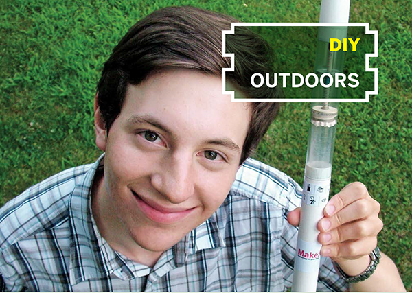
G-METER AND ALTIMETER

Double-duty aerospace instrument on a shoestring budget.
By David Simpson
Here’s an aerospace instrument you can build for $5 that will measure the crushing forces that a model rocket withstands and the rarified strata it attains. It isn’t exactly six-sigma technology in terms of accuracy, but it’s darn fun.
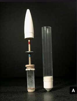
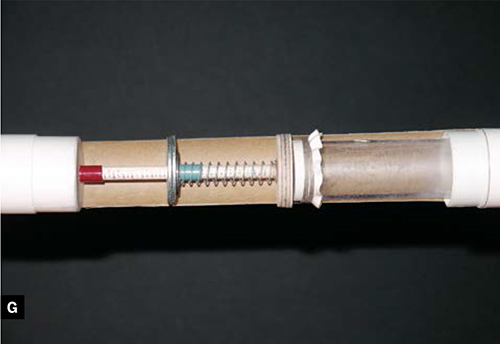
The device, which you install in the rocket’s payload compartment, uses 2 small bands of heat-shrink tubing that slide over a dowel to record the maximum G-force and altitude attained. As the rocket accelerates, the G-force band is pushed down by washers on a spring, and as the rocket rises, the altitude band is pushed down the rod by the expansion of a pressure chamber made from a pill bottle and a rubber-balloon membrane.
The force of landing doesn’t disturb the positions of the bands, which are heat-shrunk snugly over the rod and stay in place thanks to their relatively high coefficient of friction and low mass.
The “secret sauce” for both readings is the calibration step, where you mark positions on the dowel with their corresponding G-force and altitude levels. To calibrate the G-force meter, we stack increasing weights onto the spring and gauge its compression. The altimeter we calibrate using a kitchen vacuum food sealer and a commercial altimeter or barometer.
Build the Altimeter
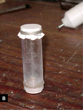
Make the flexible membrane by cutting a 2"-diameter circle from a rubber balloon. Stretch it flat over the open end of the pill bottle, and secure it by winding button thread around several times, near the top. Tie off the thread and coat it with a thin layer of wood glue or epoxy, then trim away the excess rubber.
Cut a disk the same diameter as the pill bottle out of ¼" balsa or aircraft plywood. Drill a 1/16" pilot hole in the center of the disk and glue it to the bottom of the bottle. This base will later accept a wood screw to hold the chamber fast to the tube coupler at the bottom of the payload section (Figures B and G).
Build the G-Meter
Cut a disk of 3/16" aircraft plywood just slightly shy of the inner diameter of the rocket’s payload tube, and drill a 3/16" hole in the center.
I did this in a fun way: first I traced the circumference of the body tube onto the plywood, rough-cut the disk, and drilled a 1/16" hole in the approximate center by eye. Then I threaded the disk onto a Dremel 401 mandrel bit (a shank with a screw-like head at the end) and used the Dremel as a sort of mini reverse-lathe, turning the disk down to diameter against a piece of sandpaper tacked to a board (Figure C). The mandrel bit is designed to hold polishing bits, but hey, here’s a new use! After sanding down the disk, I redrilled its center hole out to 3/16".

Glue a 3½" length of 3/16" dowel into the disk, and mark a scale on the dowel from the base to the end, in 1/16" increments, alternating between contrasting colors to make it easier to read (Figure D).

Slip a ¼" length of heat-shrink tubing over the dowel, and shrink it down until it stays in place even if you shake it like a thermometer. This is the G-force band. Slide the spring over the dowel, followed by the smaller washer and then the 2 larger washers. Now shrink another ¼" length of heat-shrink — this is the altitude band.
Prepare the Adjacent Rocket Sections
Cut 2 more disks out of 1/8" balsa, to fit the rocket’s inside diameter (Figure E). Drill one with a 1/8" hole in the center and use CA gel adhesive to attach it flat into the tube coupler piece that will take the bottom of the rocket’s payload tube, about ½" down from the top edge. This disk will anchor the altimeter chamber.

Drill a 3/16" hole in the center of the other disk and use CA adhesive to glue it into the nose cone, flush with its bottom edge.
The G-meter dowel will run through this disk and slide farther in when higher altitudes cause the pressure chamber membrane to balloon upward. The altitude heat-shrink band will meanwhile stay in place against the disk.
Assembly: No Bouncing Around!
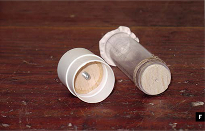
Use a short wood screw to secure the payload tube coupler to the altimeter base (Figure F). Attach the G-meter base to the altimeter membrane with a 1/18"–3/16" square of high-tack, double-sided foam tape. Use a thin film of epoxy to attach the G-meter base to the spring, the spring to the washers, and the washers to each other (Figure G).
Drill a 1/16" hole through the side of the payload section to allow external air pressure to reach the altimeter.
Calibrate the G-Meter
Calibrating this combo meter is more complicated than constructing it, but it’s both cool and educational. To calibrate the G-meter, you first build a calibration rig. Glue a 12" length of 3/16" dowel vertically in a wooden base and mark it the same way you did the G-meter dowel.
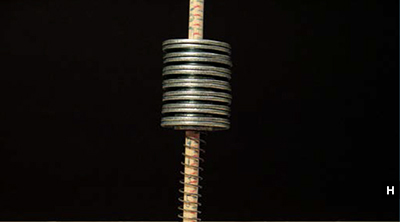
Slide the G-meter spring over the dowel and add the payload quantity of 1 small washer and 2 large washers. Check the reading on the scale. That’s 1g, our baseline. Make a table that translates millimeter readings on the dowel to corresponding G-forces. Record the 1g reading, then add 1 more small washer and 2 more large ones, and record the position on the scale for 2g. Continue doing this until you’ve got readings for 40g (Figure H). Unless you need a lot of washers, you might opt to conduct this procedure in the aisle of the hardware store.
Calibrating the Altimeter
Calibrating the altimeter is even cooler, but more involved. You’ll need access to a vacuum chamber; if you can’t gain access to a scientific or industrial vacuum chamber, borrow (or buy) a vacuum food sealer. You’ll also need an altimeter or barometer; I experimented with a RadioShack mini digital weather station, which included a barometer, but it was a challenge getting it to take instantaneous readings. I was able to do it by interrupting and re-energizing the circuit at the moment I wanted the reading. But I wound up using a good old airplane altimeter, which was simpler.
If you’re using a vacuum food sealer, put the G-meter/altimeter in a cage made by cutting two 5" windows in a 12" piece of 2" PVC pipe. The cage prevents the bag from collapsing around the instrument. Put the reference altimeter or barometer and our instrument in the vacuum bag or chamber (Figure I).

Blip the vacuum button to reduce the pressure in small increments, and record the readings from the dowel and the commercial barometer or altimeter. Make an association table between the two, like with the G-meter. If you’re using a barometer, you can convert pressure to altitude using the calculator at csgnetwork.com/pressurealtcalc.html.
Prepare for Liftoff
Make sure both heat-shrink bands are in their starting positions before each flight: the G-meter band at the top of the spring, just under the washers, and the altimeter band at the top of the dowel, so that it will be flush with the nose cone disk when you slide it on. If the nose cone is a little loose, secure it with masking tape. As with other model rockets, friction-fit the payload atop the booster, connect the elastic shock cord, and attach the parachute — or else you’ll be digging your combo meter out of a hole!
Recovery, Reading, Reset, and Repeat
After “3, 2, 1, liftoff!” and whoosh!, recover your vehicle and peek inside. You may need to loosen the bottom wood screw in order to read the bands, then use your tables to translate their positions into max-g and max-altitude. You’ve got your max-g and max-altitude recorded on the combo!
A Variation: Instead of marking millimeters on the dowels, inscribe the target units — gs and feet or meters — directly during calibration. Just take care not to bump anything while making the marks.
You’ll find that different rockets, engines, and gross weights all affect the readings. You may need to add or remove washers and recalibrate to change the overall range of the G-meter; more powerful engines need fewer washers to register a reading while weaker engines need more.
Safe rocketeering!
David Simpson is Founder of Innovators Inc. (innovatorsinc.net) whose mission is to make learning about science and technology fun and cool for kids through doing. He’s developed maker programs for the Girl Scouts and Boy Scouts as well as the Liberty Science Center and the International Spy Museum. Dave has been a mentor with FIRST Robotics and the Civil Air Patrol (CAP) and was twice named CAP’s New Jersey Aerospace Education Officer of the Year.
The Key Hole

My first job was as a bicycle mechanic at a shop where we also cut keys. One fine day, a fellow came in to have his house key duplicated, and he asked me to drill a nice big hole in the key so it would be easy to find in the dark. It wasn’t long after that when I drilled my own key! My current key ring has, among others, three identically shaped Schlage keys, so I cut a little off the wings of another to make it easy to identify. Try this trick — I’ll bet you never go back.
—Frank Ford, frets.com