
LIVING ROOM BAJA BUGGIES
By John Mouton
Photograph by Robyn Twomey
BUG’S-EYE VIEW
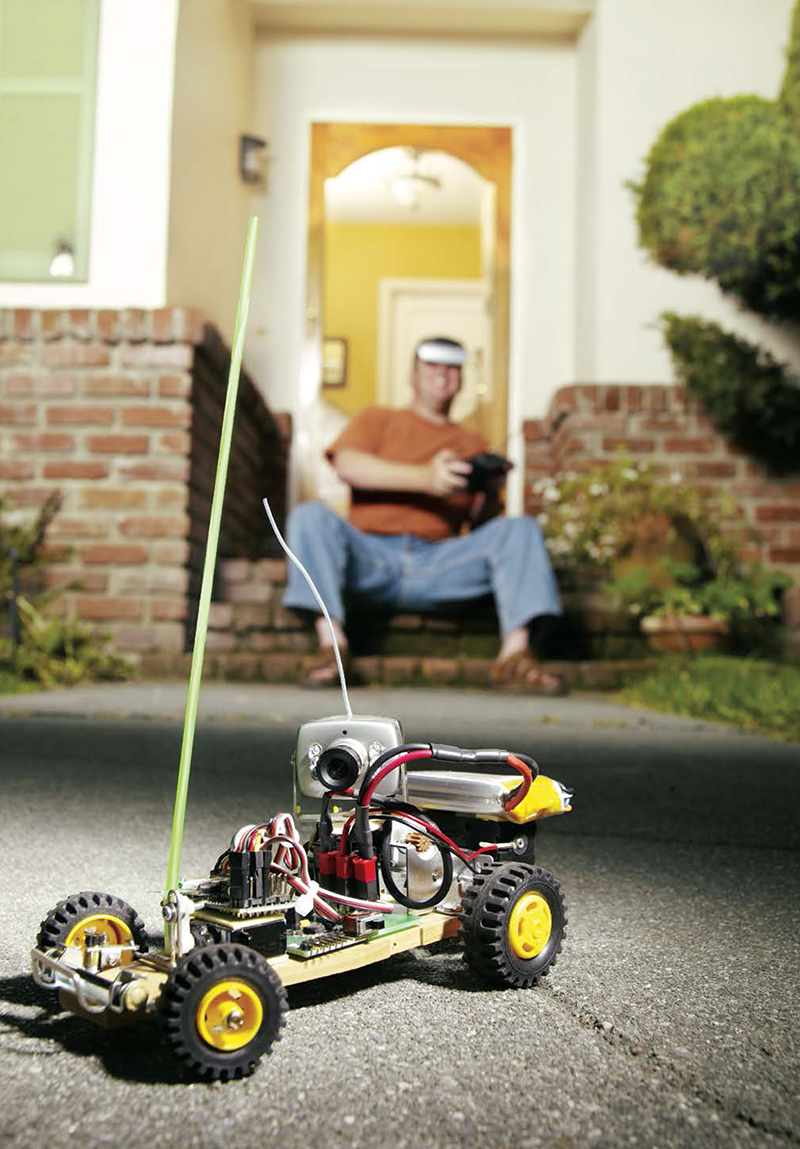
With wireless cameras on board, these radio-controlled racers give you virtual reality telepresence.
Do you like radio-controlled (R/C) cars? Do you like the desert, but hate the heat? Well, sit down and kick back as you engage in the excitement of Living Room Baja Buggy Racing. This off-road competition combines the fun of homemade R/C cars with the air-conditioned convenience of a fake, indoor desert landscape — without the big dollar price. There are no rules, no expensive automotive racing equipment, and a total disregard for public safety (because these cars are only 6" long and 4" tall).
You don’t even have to look at your car as you negotiate the terrain — an onboard camera and a virtual reality headset can be installed for your lackadaisical safety!
So chase the dog, race against the kids, or just put the electrons to the PC board and hold on for a bug’s-eye view of the whole racecourse. It’s the best thing to hit urban living since the Man Cave.
FULL DISCLOSURE:
The author is an employee of Microchip Technology, which manufactures some of the components used in this project.
R/C COMMAND, MICRO CONTROL, AND MINI VIRTUAL REALITY
In this project, we’ll build an R/C Baja buggy that you can drive around the house using a pair of virtual reality display goggles that give you a view of the world as if you were literally in the miniature driver’s seat. All of this is controlled by the user (you) via a hand-held radio transmitter and a wireless camera that displays what the buggy sees through the VR goggles.
I started by designing a simple motor control circuit, a voltage regulator circuit, and a PIC12F683 MCU. This gave me a small drive circuit that would move the buggy forward and in reverse, electrically brake and stop the buggy, and provide variable speed control.
I sent my schematic diagram and Gerber files to a vendor and got back a printed circuit board, ready to plug my components into.
After the circuit was built, I bought parts on the internet to build the buggy. When I put the buggy into action I found that it performed well — in fact, better than I expected.
I added a wireless camera and virtual reality goggles. Now I drive the buggy all over the house without leaving the comfort of my couch. You don’t have to add the wireless camera and virtual reality goggles to have fun with this project. In fact, the buggy will be less expensive and lighter without them. Nevertheless, this article provides step-by-step instructions on how to build an R/C Baja buggy with the whole enchilada.
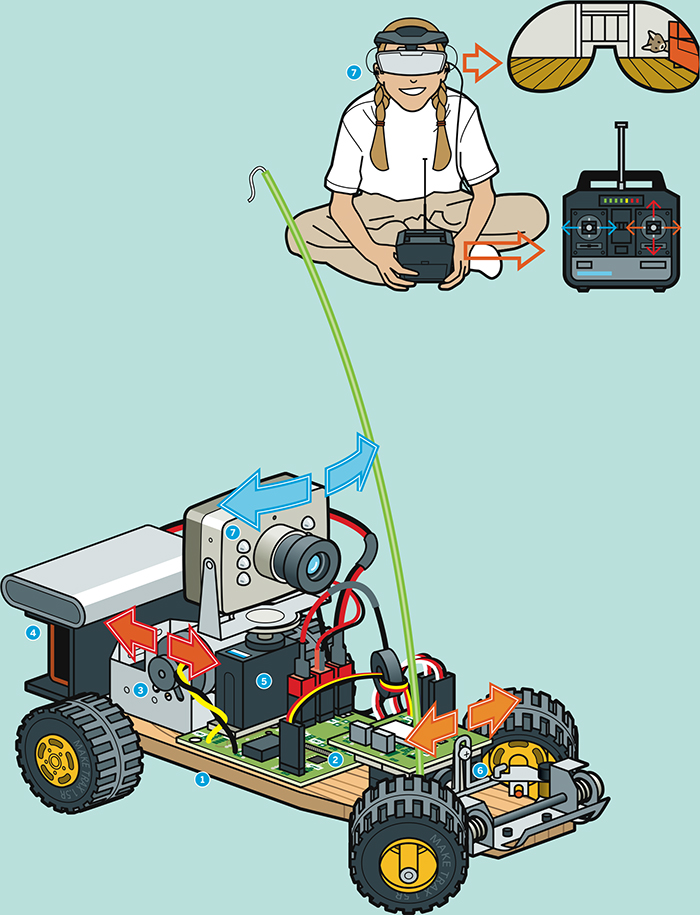
Illustration by Nik Schulz
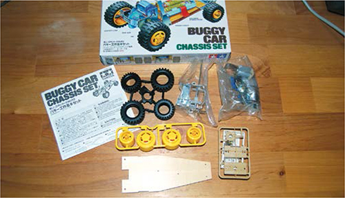
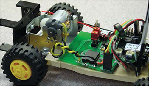
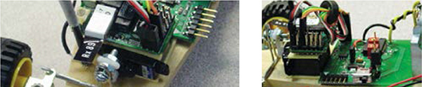
![]() The Baja buggy is built on a Tamiya Buggy Car Chassis Set.
The Baja buggy is built on a Tamiya Buggy Car Chassis Set.
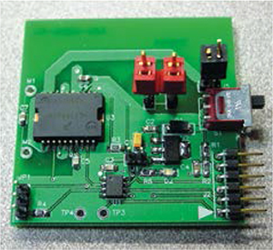
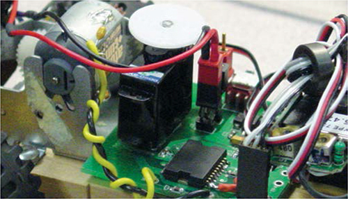
![]() The motor control circuit is built on a custom printed circuit board.
The motor control circuit is built on a custom printed circuit board.
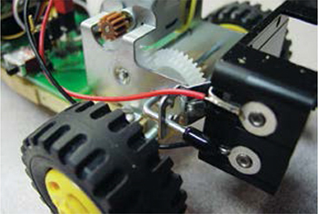
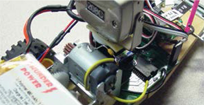
![]() The drive motor (red arrows) makes the buggy go forward and backward.
The drive motor (red arrows) makes the buggy go forward and backward.
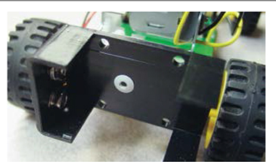
![]() A 9V battery and a lithium battery add weight to the back for improved traction.
A 9V battery and a lithium battery add weight to the back for improved traction.
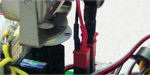
![]() One servomotor (blue arrows) pans the webcam mounted on top.
One servomotor (blue arrows) pans the webcam mounted on top.
![]() Another servomotor (orange arrows) steers the front wheels.
Another servomotor (orange arrows) steers the front wheels.
![]() The wireless webcam signal is sent to the VGA virtual reality goggles.
The wireless webcam signal is sent to the VGA virtual reality goggles.
SET UP.

Photography by John Mouton (left) and Ed Troxell
MATERIALS
Wireless camera and tuner/receiver You need a wireless 9V DC, 300mA A/V security camera, and a 9V DC, 500mA tuner/receiver with 0.9G frequency control. Try tigerdirect.com or frys.com
VGA goggles Any wireless-capable generic or name brand; try amazon.com or tigerdirect.com
Tamiya Buggy Car Chassis Set #70112 tamiyausa.com
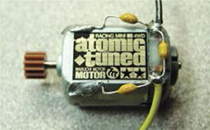
Tamiya Atomic-Tuned DC Motor #15215
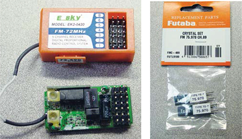
E-Sky EK2-1003 4-channel radio system which includes transmitter, receiver, and 1 servomotor (mini), or similar radio system
E-Sky EK2-0500 servo-motor for the camera Futaba FM75.470 MHZ CH.64 crystal For multiple buggies, use different crystals in the 75MHZ–76MHZ range to avoid cross-talk.
Thunder Power lithium polymer (Li-Poly) 1,320mAh/7.4V, 2-cell rechargeable battery for the motor
9V battery for the camera
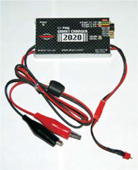
Apache Smart Charger 2020 for charging the Li-Poly batteries
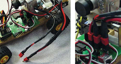
Electrifly 2-pin male connectors #GPMM3106, for all battery, camera, and charging connections
Servo cable with 1 male s connector towerhobbies.com #LXPWB5
Male S connector for servo cable, Tower #LXPWC3
Ferrite ring for radio- control applications, check digikey.com
Battery holder digikey.com #1294K-ND #4 3/8" Phillips head screw, #4 flat washers (2), and 4-40 steel hex nuts (2) for tie rod hardware
NOTE: For the R/C transmitter, receiver, servos, and crystal, try hobby-lobby.com and jameco.com for the batteries and charger, try rctoys.com and electrifly.com.
TOOLS
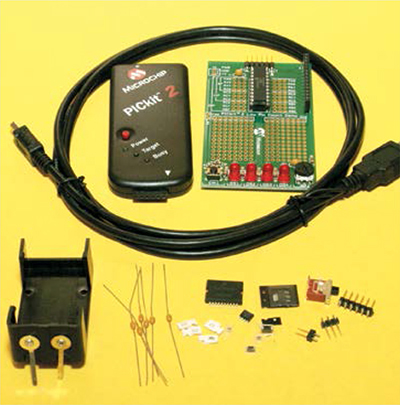
PICkit 2 Starter kit for programming microchipdirect.com
Electric drill, cordless or AC
Drill bits to fit the rivet diameter
Center punch
Soldering iron and solder
Double-sided tape
Sandpaper
Computer
Phillips screwdrivers large and small
Side cutters, modeling knife, and scissors
Pop rivet tool, hand-held
Heat-shrink tubing
Heat gun or hair dryer
Wire strippers
Needlenose pliers
Fake desert landscape
DOWNLOADS
Download the Baja buggy motor control program for your PIC microcontroller, carprogorig.hex, as well as the Gerber files. Then download a complete list of the circuit components. makezine.com/projects/ living-room-baja-buggies
MAKE IT.
BUILD YOUR OWN VIRTUAL REALITY BAJA BUGGY
Time: 4–5 hours Complexity: Medium
START ≫
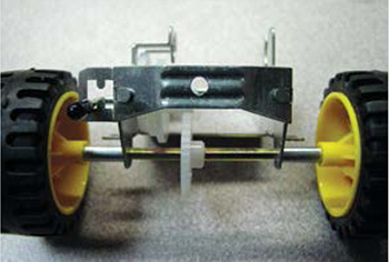
1. BUILD THE BUGGY CHASSIS
1a. Assemble the buggy chassis set as directed in part 3 of the instructions enclosed in the Tamiya Buggy Car Chassis Set box.
1b. Drill a hole in the back of the motor/gear bracket housing. You’ll use it to rivet on the 9V battery holder. Use the same drill bit size as the size of your rivet.
NOTE: Center-punch the hole before you drill, and use a high-quality drill bit with a sharp tip. This will prevent the drill bit from skipping across the metal and biting in the wrong place.
1c. Modify the tie rod. Bend and trim a 16-gauge wire to about 1" high with arms that fit against the tie rod provided in the buggy car chassis kit, as shown. Then solder the 2 together. This will give the servo a way to move the tie rod left, right, up, and down with the suspension, thus steering the buggy.
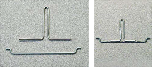
Photography by John Mouton
1d. Solder one 0.1-microfarad (μf) capacitor and a 24-gauge wire from each lead of the atomic-tuned DC motor to the motor case. Next, solder a third 0.1μf capacitor between the leads. This will prevent electrical motor noise from interfering with the receiver circuit.
1e. Install the wheels as directed in part 6 of the buggy car instructions. However, don’t install the roll bar — it will just be in the way later when you install the camera servo and the motor-control circuit board.
2. BUILD THE MOTOR-CONTROL CIRCUIT
2a. Get a printed circuit board. I emailed the schematic and Gerber files provided at makezine.com/projects/living-room-baja-buggies to Circuit Express (circuitexpress.com). I chose their least expensive package, 10 boards for $120, and they built the boards and mailed them to me within 24 hours. Other vendors are less expensive for smaller quantities. Or you can buy a PCB build kit and make it yourself.
2b. Install the circuit components. All components used in the motor-control circuit can be purchased from Digi-Key (digikey.com) or any other electronic components supplier. For the battery, camera, and charger connections, I used ElectriFly 2-pin male connectors to ensure safe, secure connections. I chose the PIC12F683 MCU because it’s small, has a pulse-width modulation (PWM) module onboard, and very simple to work with. Here’s what the completed circuit board should look like after all the components are soldered. Use the schematic to guide you. A list of components and part numbers is available at makezine.com/projects/living-room-baja-buggies.
3. INSTALL CIRCUIT BOARD, BATTERY HOLDER, AND SERVOMOTORS
3a. Before you solder the motor leads, twist them together. This will keep electrical motor noise from interfering with the receiver. Now solder them to the circuit board at the locations marked M1 and M2.
3b. Use a small piece of double-sided tape to attach the circuit board to the wooden chassis, all the way back so that it touches the motor/gear bracket housing.
3c. To install the 9V battery holder, first sand off about 1/16" of its bottom end. This ensures that the battery will fit flush inside, and that the holder itself will fit evenly and spaciously between the rear wheels.

3d. Drill a hole in the center of the battery holder the same diameter as the hole you drilled in Step 1b. Then rivet the battery holder to the motor/gear bracket housing.
NOTE: To rivet, insert a rivet through the hole, and then squeeze with the pop rivet tool until the shaft pops off. To remove a rivet, drill it out using the same bit you used to drill the original hole.
3e. Extend the battery holder’s positive and negative leads by soldering 24-gauge wires to them, long enough to comfortably reach J4 on the motor-control circuit board. Solder a 2-pin male connector to the ends of these wires, which will allow you to disconnect the 9V camera battery from the circuit board as needed.
3f. Using a small piece of double-sided tape, attach 1 servomotor to the motor-control circuit board as close to the motor/gear bracket housing as possible. This servo will be used to pan the wireless camera that will be mounted on top of it.
The servos come with an assortment of lever arms that can be attached to them, depending upon the application. Use the circular lever arm on the camera servo.
3g. Next, attach the other servo to the chassis just in front of the circuit board (the location is shown in Step 3e). This second servo will be used to steer the buggy.
3h. For the steering servo, use the straight lever arm. Drill a small hole in the lever arm the diameter of a #4 screw. Use the #4 screw, 2 washers, and two #4 nuts to loosely attach your modified tie rod to the servo lever arm. Now, as you drive the car over rough terrain, the servo will still be able to steer the front wheel even as the front suspension moves up and down.

4. INSTALL THE R/C RECEIVER AND WIRELESS CAMERA
4a. You can use just about any R/C transmitter/receiver set for this project. If you don’t already have a set, shop around for a good deal. I found a great deal on a 4-channel radio system kit that included the transmitter, receiver, and 1 servo for $60.
The reason I chose a 4-channel dual stick transmitter (rather than a 2- channel pistol-type transmitter) is because I needed the second left-to-right stick to pan the camera.
4b. Using double-sided tape, attach the receiver to the top of the steering servo. To reduce the receiver’s bulkiness, remove its cover. This allows you to easily install frequency crystals and plug components into the receiver.

4c. Plug the camera servo into channel 4, and the steering servo into channel 1. Plug connection JP1 of the motor-control circuit board into channel 3 of the receiver; this connection will supply power to the receiver and allow you to control the speed of the motor via the PWM signal generated from the PIC12F683 MCU. Make the PWM signal cable by crimping the male S connector’s pins to the bare-wire end of the male servo cable using a pair of pliers. Now, in order to reduce electronic noise interference, loop the PWM cable through a ferrite ring before plugging it into channel 3 of the receiver. This ring will increase the cable’s inductance, thereby filtering out high-frequency electronic noise.
![]() CAUTION: When using R/C transmitters and receivers for cars, keep them in the R/C car frequency range of right around 75MHZ.R/C airplanes operate right around the 72MHZ frequency range.
CAUTION: When using R/C transmitters and receivers for cars, keep them in the R/C car frequency range of right around 75MHZ.R/C airplanes operate right around the 72MHZ frequency range.
4d. Before installing the wireless camera to the camera servo, shorten the camera’s cable and solder another 2-pin male connector so it will plug into the motor-control circuit board at J3. To do this, cut the camera’s cable down to about 3". Strip 1" of insulation and slide on a 2" piece of heat-shrink tubing. Then solder the black and red wires to the 2-pin connector, slide the heat-shrink tubing over the connection, and shrink it with a heat gun or hair dryer.
4e. Using your double-sided tape, attach the wireless camera to the camera servo temporarily (you’ll adjust it later).
5. INSTALL THE MOTOR BATTERY AND PROGRAM THE PIC MICROCONTROLLER
5a. For the motor’s power source, you need something that will supply enough voltage and last a while between charges. I used a Thunder Power lithium polymer (Li-Poly) 1,320mAh/7.4V 2-cell rechargeable battery. I don’t recommend using less than a 480mAh/7.4V battery, as it would need to be recharged more often.
![]() CAUTION: The battery will have a charge even if you buy it brand-new, so keep the 2 wires from touching!
CAUTION: The battery will have a charge even if you buy it brand-new, so keep the 2 wires from touching!
5b. Strip the black and red wires coming off the battery. Solder the wires to another 2-pin male connector, and heat-shrink. Attach the battery to the 9V battery holder with double-sided tape, and connect the rechargeable’s wires to J5 (VBAT) on the circuit board.
5c. To program the PIC MCU, I used a PICkit 2 Starter Kit (#DV164120) that I bought from my company, Microchip Technology (microchipdirect.com) for $50. This kit has everything you need to write, debug, and program your source code directly into the MCU via header J2 on the circuit board. (If you’re a student or educator, visit microchip.com/academic to learn how you can get a discount on development tools through Microchip’s Academic Program.) Go to makezine.com/projects/living-room-baja-buggies. All you have to do is to import the carprogorig.hex program file using the PICkit 2 Starter Kit interface, and then click the Program button.
NOW GO USE IT »
FINISH X
USE IT.

CHARGE IT UP
CHARGE IT
Now that your buggy is assembled, you’re almost ready to turn it on. However, you might want to charge the battery first. I used an Apache Smart Charger 2020 designed specifically for charging 2-cell Li-Poly batteries.
![]() CAUTION: Trust me when I say that if you use lithium polymer batteries, you must use a charger designed to recharge Li-Poly batteries. I have a coworker who no longer has a garage because her husband didn’t use the appropriate battery charger. Always follow the manufacturer’s instructions on proper use of batteries and chargers.
CAUTION: Trust me when I say that if you use lithium polymer batteries, you must use a charger designed to recharge Li-Poly batteries. I have a coworker who no longer has a garage because her husband didn’t use the appropriate battery charger. Always follow the manufacturer’s instructions on proper use of batteries and chargers.
ZERO THE SERVOS AND SET THE RADIO CONTROLS
You’re now ready to fire up your buggy. Once you turn on S1 on the circuit board, the servos will power up and find their neutral positions. Hence, you’ll need to detach the camera and reattach it so it faces toward the front of the car. (Good thing you used double-sided tape!) You may also need to make a slight adjustment to the steering servo. Simply remove the screw holding the lever arm to the servomotor, pull it off, and reattach it, pointing straight up. Now, when you turn S1 off and then turn it back on, the servos will be aligned to the correct starting points.
With the circuit board and hand-held transmitter both turned off, adjust the transmitter toggle switches in the lower right-hand corner to set the left control stick (forward and back) as the throttle; the left control stick (left and right) for steering; and the right control stick (left and right) for panning the camera. The radio system kit’s instruction manual will help you do this.
When finished, turn the transmitter on, then turn the circuit board power on at S1. Take the throttle control stick on the transmitter and pull it all the way back toward you. Then push it all the way forward, then back to center. This will establish the maximum duty cycles for forward and reverse, and arm the speed control circuit. At this point, the buggy is ready to roll.
USING THE VIRTUAL REALITY GOGGLES
Plug the VR goggles (or a TV monitor) into the receiver that came with the wireless camera. Plug the receiver into an AC outlet. Adjust the tuning knob until a picture of what the camera sees comes up. I found that the wireless camera range is more than 500' straight line-of-sight, with no major obstacles. If you use it outside in a large open area, the range is even better.
RESOURCES
![]() Download the Baja buggy motor control program for your PIC microcontroller, carprogorig.hex, as well as the Gerber files and circuit schematic from makezine.com/projects/living-room-baja-buggies. You can also download an Excel file listing all the Digi-Key part numbers for components that fit this circuit board. And finally, there’s a list of lower-cost build alternatives provided.
Download the Baja buggy motor control program for your PIC microcontroller, carprogorig.hex, as well as the Gerber files and circuit schematic from makezine.com/projects/living-room-baja-buggies. You can also download an Excel file listing all the Digi-Key part numbers for components that fit this circuit board. And finally, there’s a list of lower-cost build alternatives provided.
Microchip’s Online Motor Control Design Center (microchip.com/motor) has a wealth of resources for programming your PIC microcontroller to control motors and more.