
BOOM STICK
By Edwin Wise
Photograph by Garry McLeod
DECOMPRESSION THERAPY
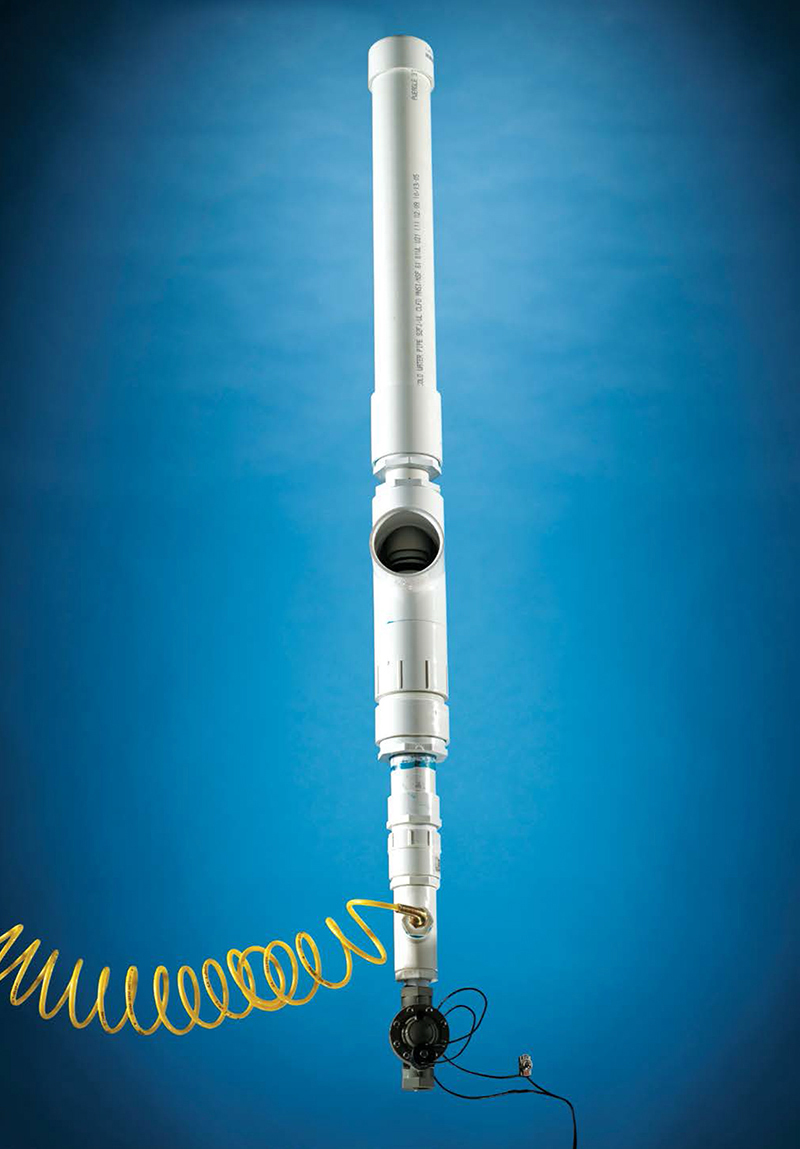
The super-loud Boom Stick is a PVC air cannon that delivers maximum bang for the buck. It assaults the startle reflex of any nearby victim, adding an instant rush of physical terror to haunted houses, art pieces, pranks, and performances.
I work in haunted houses during the Halloween season, as an actor, guide, technician, makeup artist, and effects creator. Some of my effects instill fear through foreshadowing or complex storylines, but the most effective way to scare people is often just a simple, brute-force startle.
The air cannon is a great and safe device for such scares. In its simplest form, it consists of an air reservoir, a quick-exhaust valve (QEV), and sometimes a resonating chamber. Haunted house suppliers and special-effects houses sell commercial models with large-gauge QEVs, but these cost hundreds of dollars. Home projects that rely on a standard air compressor typically use smaller, cheaper water valves from washing machines or sprinklers, but for me, these designs have yielded only a disappointing “poof-hiss.”
Inspired by the PVC-based designs of spud gun enthusiasts (but leaving out the potato), I’ve found a better approach: a two-stage, chamber-sealing, quick-exhaust, piston-valve air cannon that you can build out of common plumbing components for about $100. I call it the Boom Stick.
The Boom Stick creates a pressurized volume of air and releases it very quickly, generating a loud shockwave.
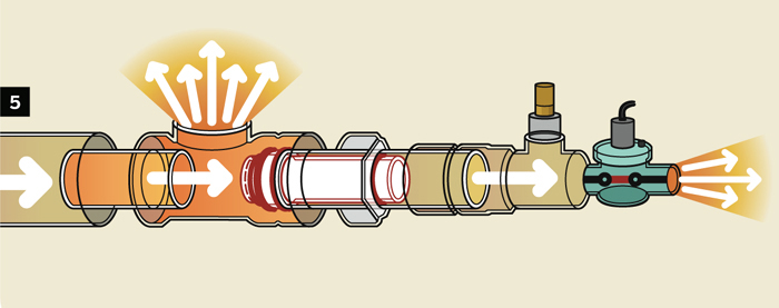
HOW IT WORKS
1. The piston rests in the piston carrier, and the entire system is at ambient air pressure. Small holes in the piston allow limited airflow through from behind; a rubber washer inside the piston acts as a check valve, passing air in only one direction and increasing efficiency.
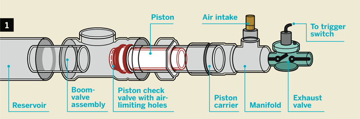
Illustration by Damien Scogin
2. When air flows in behind the piston faster than it leaks out of the holes, pressure builds up in the manifold.
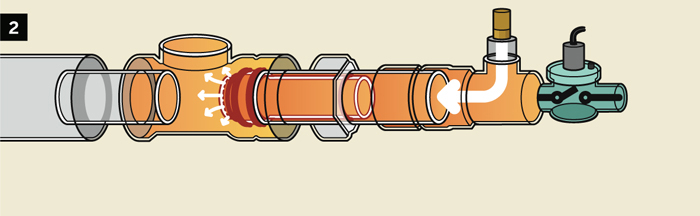
3. Pressure behind the piston pushes it into the boom valve tube, sealing the pathway between the air supply and reservoir.
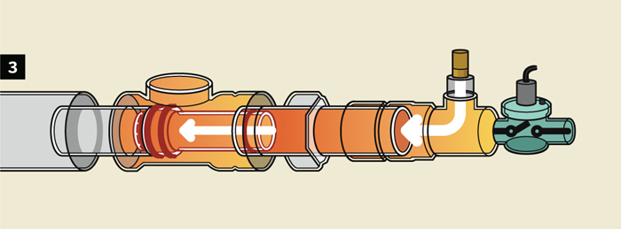
4. Pressurized air slowly fills the reservoir through the holes in the piston. The cannon is loaded once the pressures between manifold and reservoir balance.

5. To fire the cannon, a small exhaust valve opens and releases air pressure behind the piston, drawing the piston back into the manifold. As soon as the piston clears the boom valve tube, the pressurized contents of the reservoir release into the atmosphere with an impressive bang.
SET UP.
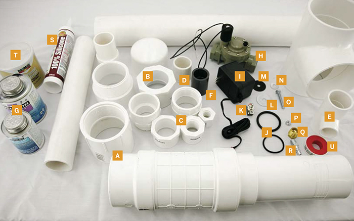
Photograph by Sam Murphy
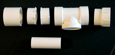
MATERIALS
[A] 3" diameter PVC parts:
» 18"–24" long pipe
» Tee fitting with female pipe thread (FPT) stem
» Repair coupling
» FPT to slip adapter
» Male pipe thread (MPT) to slip adapter
» End cap
[B] 2" diameter PVC parts:
» 15" long pipe
» FPT to slip adapter
» MPT to slip adapter
» Insert coupling ProPlumber model #PPFC200. Only carried at Lowe's
[C] PVC reducing bushings:
» 3" to 2" slip (2)
» 2" to 1½" slip
» 1½" slip to 1" FPT
» 1" slip to ½" FPT
[D] 1½" PVC pipe, 2" long
[E] PVC reducing tee fitting, 1½"×1"×1½"
[F] 1" repair coupling, Schedule 80 PVC must fit inside 2" insert coupling
[G] PVC primer and medium-thickness glue
[H] Irrigation valve, 24V solenoid with 1" MPT ends A cheap one ($10) is fine.
[I] 24V power supply Look in the irrigation aisle next to the valves.
[J] 2" O-rings, 6" thick (4)
» 1¾" O-rings, 1" thick (4)
[K] On-off switch, SPST
[L] Fender washers, 13" with 7" hole (2)
[M] Neoprene washer, 1½" with 5/16" hole
[N] 7" washers (2)
[O] 7" bolt, 2" long
[P] 7" lock nut with nylon insert
[Q] Brass pipe adapter, ½" MPT to ¼" FPT
[R] Quick-release pneumatic coupling, ¼" MPT
[S] Silicone caulk
[T] Lithium grease
[U] Teflon pipe tape
TOOLS
[NOT SHOWN]
Plumber’s epoxy putty (optional)
Air compressor that can produce 40–60psi An air tool compressor is best.
Tape measure
Hacksaw or pipe cutter
Crescent wrenches at least 2
Vise capable of clamping the flange of 3" bushing
Gloves and goggles
Sandpaper coarse and medium grits
Electric drill with grinding stone bit
Drill press or lathe
Popsicle stick
File (optional)
MAKE IT.

BUILD YOUR OWN BOOM STICK
Time: A Day Complexity: Medium
START ≫
1. MODIFY THE PVC FITTINGS
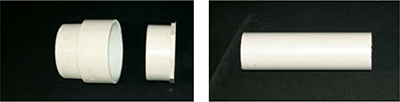
1a. Take two 3" to 2" bushings and grind out the ridge inside them with a drill using a grinding stone bit, so that the 2" pipes can slide firmly through.

1b. Sand down both sleeves of the 2" insert coupling so they slide easily into 2" pipes. You can bolt the part between 2 fender washers, chucking it into a drill press, and sanding carefully on both sides to keep it from flying off. This will be our moving piston body.
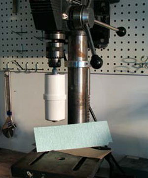
Photography by Edwin Wise
NOTE: Don’t let the PVC get hot or it will melt and deform. Use light pressure and moisten it occasionally to keep it cool. Start with coarse-grit. sandpaper and finish with medium-grit.
![]() CAUTION: DANGEROUS PROJECT At normal temperatures, standard Schedule 40 PVC. has a working pressure of around 150psi, but heat, sunlight, solvents, scratches, and time make the material lose strength, and even at the 40–60psi used for this project, it will eventually fail. When it does, it will break into fragments that will be thrown with great force by the compressed air. Always operate your Boom Stick inside a Solidly built plywood box or wall, so that shrapnel cannot reach anyone’s tender flesh. ABS plastic does not shrapnel like PVC, but the common type used for DWV (drain/waste/vent) applications is not pressure-rated, so it may or may not hold up. Foam-core PVC or ABS is even more lightweight and MUST BE AVOIDED AT ALL COSTS.
CAUTION: DANGEROUS PROJECT At normal temperatures, standard Schedule 40 PVC. has a working pressure of around 150psi, but heat, sunlight, solvents, scratches, and time make the material lose strength, and even at the 40–60psi used for this project, it will eventually fail. When it does, it will break into fragments that will be thrown with great force by the compressed air. Always operate your Boom Stick inside a Solidly built plywood box or wall, so that shrapnel cannot reach anyone’s tender flesh. ABS plastic does not shrapnel like PVC, but the common type used for DWV (drain/waste/vent) applications is not pressure-rated, so it may or may not hold up. Foam-core PVC or ABS is even more lightweight and MUST BE AVOIDED AT ALL COSTS.
Pressure-rated ABS such as Duraplus from Ipex (ipexinc.com) is the perfect material for this project, but it costs 10 times as much as Schedule 40 PVC. Copper and other metal pipes are similarly expensive.
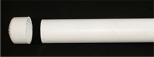
1c. Cut the pipe pieces down to size. For the reservoir, cut an 18"–24" length of 3" pipe. For the boom valve and piston carrier tubes, cut 2 lengths of 2" pipe, one 6" and the other 8". For the air fittings, cut a 2" stub of 1½" pipe.
1d. Cut the 1” Schedule 80 repair coupling into a 1¼" section and a 1" section. There may be ¼" or so of scrap left over.
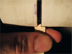
1e. Cut the sanded insert coupling into 3 pieces by trimming a 8/3" ring off one end and chopping enough of a sleeve off the other end to leave a 11/16" stub.
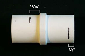
NOTE: The measurements need not be exact, but look at the photos for Steps 2c–2e on the next page to see how this piece is used.
1f. File or sand the ends of the pipes smooth. File or sand a bevel on one side of the 3/8" coupling ring and the boom valve (2"×6") pipe. These bevels will correct minor alignment errors during operation.
2. ASSEMBLE THE PISTON
2a. Drill four 1/8" or smaller holes in one fender washer, just outside the radius of the regular 5/16" washers that will be mounted over them. Drill four ¼" holes in the other fender washer, also outside the radius of the smaller washers.
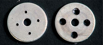
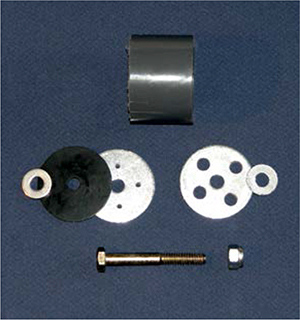
2b. Run the bolt through, in order: a small washer, the neoprene washer, the small-drilled fender washer, the 1¼" Schedule 80 PVC segment, the large-holed fender washer, another small washer, and the lock nut. Tighten the lock nut just enough to hold the assembly firm, but not so much so that the neoprene distorts.
NOTE: The neoprene washer limits airflow, which lets pressure push the piston forward into position. When the pressure balance reverses, it seals the piston as it travels back in order to put all the air into the boom.
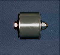
2c. Fit two 2" O-rings onto each end of the main piece of the sanded insert coupling. Then test-assemble the entire piston. Using the other 2 pieces of the insert coupling and two 1¾" O-rings, enclose the 1" Schedule 80 PVC segment and the piston valve assembly as shown.

NOTE: Pipe fittings are tapered, which makes it harder to get the parts to fit together nicely when they’re cut. Use epoxy putty or gel to reinforce the construction as needed.
2d. Use PVC glue or epoxy to glue the piston together. First, glue the ¾" Schedule 80 segment into the 3/8" ring, on the side opposite the bevel. Place a small O-ring as a spacer on the segment, and glue this subassembly into the body of the insert coupler.

2e. Glue the piston valve halfway into the assembly, with the neoprene washer facing in. Then glue the remaining insert coupler piece around the outside half, with another small O-ring spacer in between. Reinforce the connections with epoxy.
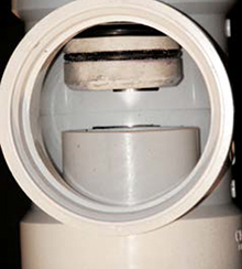
3. FIT THE O-RINGS
The large O-rings are bumpers that protect the PVC during operation. The small O-rings form the piston’s seal inside the piston carrier and boom valve cylinders. The long end of the piston must mate with the 2"×8" pipe, and the short end with the 2"×6" pipe. The goal is for the piston to be able to fit into the pipe and seal via the O-rings. These can be tricky to get right. With the PVC parts I bought, the perfect-sized small O-ring would be 5/32" thick. But I only found them available in 1/8" and 3/16", so I used the 1/8" size and pushed them out with a layer of silicone caulk underneath.
3a. Glue flowed onto the small O-rings in previous steps. This isn’t good for them, so once the glue dries, cut or pry them off and discard. Replace with the remaining 2 small O-rings.
3b. Glue the large O-ring bumper pairs together with silicone caulk. This keeps them from jumping off. (You can also try one thicker O-ring on each side.)
3c. Out of a popsicle stick, make a small tool that fits a groove 1/8" deep and 1/8" wide. Fill the piston grooves with silicone caulk, and use the tool to remove all but the thin layer that it can’t reach. This will help the small O-rings make a seal.

NOTE: You may need to do this several times before the o-ring seals and the piston slides. Even with everything fitting and well greased, the difference between success and jamming or leaking is subtle.
4. ASSEMBLE THE BOOM VALVE AND PISTON CARRIER
4a. For the boom valve assembly, use PVC glue to weld one of the slide-through-modified 3" to 2" bushings into one end of the 3" tee fitting, and the 3" female adapter into the opposite end. Weld the unmodified 3" to 2" bushing into the 3" repair coupling. Wait for the glue to dry, and then dryfit each end of the 2"×6" pipe into the 2 bushings, with the beveled end in the tee assembly.
4b. For the piston carrier, PVC-weld the other modified bushing into the 3" male adapter. Let the glue dry, and then test-fit the 8" piston carrier pipe into the bushing.
4c. Slide the long end of the piston into the carrier pipe and screw the piston carrier male adapter into the boom valve assembly female adapter.
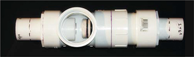
4d. Adjust the 2 pipes in their bushings until the piston (without its O-rings) travels freely between carrier pipe and boom valve assembly. The small O-rings should tuck inside both tubes when the piston is extended, and you can see a gap between the piston and the valve pipe when the piston is retracted. Proper alignment is key. Mark the position of the 2 tubes, remove them (and the piston) from the bushings, and then weld the tubes back into place at the marks.
4e. Mark the positions of everything. Then remove the piston, unscrew the 2 assemblies, and glue in the tubes. Apply primer and glue only to the 2" pipes inside the marks and not the bushings, or else you’ll foul the ends of the pipes.
4f. Weld the unmodified bushing and repair coupling assembly to the other end of the valve pipe, and the 2" male adapter to the free end of the carrier pipe. Alignment isn’t so important with these.

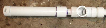
5. ASSEMBLE THE RESERVOIR AND MANIFOLD
Unlike the valve/piston system, the reservoir and manifold are low-precision designs that will tolerate variation.
5a. For the reservoir, weld the 3" end cap onto one end of the 3"×18"–24" pipe, and weld the other end into the repair coupling on the boom valve assembly.
5b. For the manifold, weld the short piece of 1½" pipe into one side of the 1½" tee fitting and weld its other end into the 2" to 1½" reducing bushing. Weld the 2" female adapter to the bushing.
5c. Screw the inlet port of the 1" irrigation valve into the 1½" slip to 1" female threaded bushing, using Teflon tape to seal the threads. The flow arrows should point away from the bushing. Tighten firmly. This is the exhaust valve.
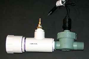
5d. Weld the exhaust valve subassembly into the other side of the manifold tee fitting, orienting the wiring connections as desired. For the trigger, connect the on-off switch to either of the 2 wires.
5e. Weld the 1" slip to ½" female threaded bushing to the center port of the tee fitting. Wrap Teflon tape around the brass adapter and thread it into the bushing, and then Teflon-tape the quick-release coupling into the adapter. This is the air intake.
6. FINAL ASSEMBLY
6a. Allow 24 hours for all of the PVC solvents and glues to cure. Remember, patience is a virtue.
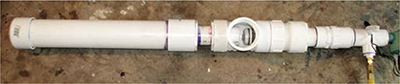
6b. Lather up the piston and all the O-rings with lithium grease. Insert the piston into the piston carrier with its valve aiming toward the reservoir.
6c. Screw the piston carrier back into the boom valve assembly. This connection does not need to be airtight, but the carrier pipe and valve pipe must be aligned.
6d. Wrap several layers of Teflon tape around the 2" male adapter on the piston carrier, and screw it into the air manifold. You’re done!
FINISH X
NOW GO USE IT »
USE IT.
GO BOOM
BOOM STICK OPERATION
Attach an unpressurized air hose to the quick-release fitting on the air intake.
Attach the 24V power supply to the exhaust valve and trigger switch.
Test the exhaust valve to make sure it works.
Put the entire system in a sturdy box or solid wall, or at least behind a blast shield.
Pressurize the manifold to about 40psi. The piston should snap into the valve tube and the reservoir should fill with a hiss. If the piston doesn’t fit into the valve tube, the small O-rings may be pushed out too far. If the air leaks around the O-rings, they are not out far enough. If the tubes are misaligned, you may have to rebuild the piston carrier.
Activate the trigger switch for about half a second. The pipe behind the piston will lose pressure and the piston will slam back into the carrier pipe, exhausting the reservoir.
Jump for joy at the loud bang!
Repeat.
FIXES
The hard part in this design is getting the O-rings to seal firmly without jamming the piston’s motion. If you just can’t get them to seal, never fear; add a second irrigation valve to the air inlet, and only let air in just before you want to set off the device. The effect won’t be as clean, but you’ll lose less air during operation.
The piston carrier is modular for a reason: you can remove it easily and experiment with different piston designs (of which there are many), and you can replace the piston if it breaks. Also, if you glue the piston carrier into place with bad alignment to the valve tube, you only have to throw away a few inexpensive pieces to try again.
To keep stuff from falling into the Boom Stick, cover all openings in its box with hardware cloth.
RESONATING CHAMBERS AND CONFETTI
Once you get the basic Boom Stick working, create a resonating chamber by gluing a 3" male adapter onto some 3" pipe, and screwing it into the cleanout port on the boom valve’s tee fitting. Try constricting the exhaust, putting a 3"×2" or even smaller bushing into the base of this chamber. Try long ones and short ones. Stuff confetti into the chamber and make a mess of your workshop. But never, ever launch anything directly at anyone!
ACTION VIDEO
![]() See Wise’s Boom Stick in action at makezine.com/go/boomstick. But note that the boom sound is mostly lost. Microphones can only do so much.
See Wise’s Boom Stick in action at makezine.com/go/boomstick. But note that the boom sound is mostly lost. Microphones can only do so much.
RESOURCES
Huge list of haunter how-tos: halloweenmonsterlist.info
O-Ring Handbook: dichtomatik.us/products/o-ring-handbook
Generally useful site with size and pressure specs for PVC: engineeringtoolbox.com
OSHA warning memo on pressurized PVC: makezine.com/go/oshapvc