In this recipe, we will create a realistic rock material similar to the one shown in the following screenshot:
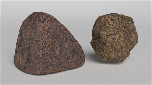
The best way to start this task is by using image maps. Image maps are particularly useful for several reasons: they already have the necessary color information of a natural surface ready to use. They can be easily edited in any image editor to obtain different information as, for example, high levels for the bump maps. They are processed faster than procedurals by the software (procedural textures must be calculated every time). Moreover, they can be easily found for free on the Web in several sizes and resolutions.
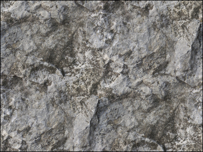
Just remember to make any image you are going to use "tileable" using your preferred image editor. In Gimp, this job is automatically done by a plugin under Filter | Map | Make Tileable.
Open the 1301OS_03_start.blend file, which is a simple layout ready for material creation:
- On layer 1 there are a smooth-subdivided "spheroid" cube and a modified plane, with extruded and curved vertical walls working as a backdrop and a default white material assigned.
- On layer 6 there is a mesh-light, a big plane, with a white emission material set to an intensity of
6.000. - There is also a dark gray World, set to an intensity of
0.100and with an Ambient Occlusion set to a Factor of0.10but left unchecked.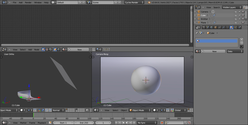
Carry out the following steps to create a rock material:
- Select the subdivided cube and, for the purposes of this exercise, delete it by pressing X from the keyboard.
- With the mouse pointer in the 3D window, press Shift + A to pop up the Add menu and add a new Cube primitive (press Shift + A and go to Mesh | Cube). Press Tab to go out of edit mode if needed.
- Click on New in the Material window on the right, under the Properties panel, or in the header of the Node Editor window.
- Put the mouse in the Node Editor window and add an Image Texture node (press Shift + A and go to Texture | Image Texture), then add a Mapping node (press Shift + A and go to Vector | Mapping) and a Texture Coordinate node (press Shift + A and go to Input | Texture Coordinate).
- Connect the Texture Coordinate node's Generated output socket to the Vector input socket of the Mapping node, then its Vector output to the Vector input of the Image Texture node. Also connect the Image Texture node's Color output to the Color input of the Diffuse BSDF shader.
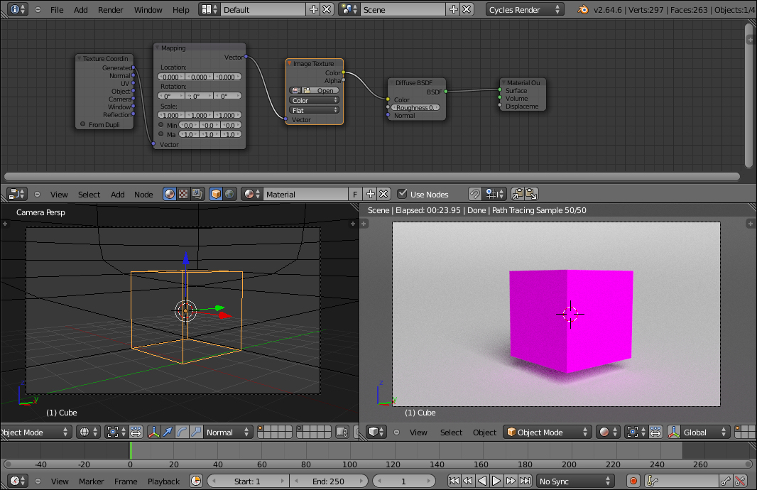
- Set the mode of the Camera view to Rendered. The rendered cube turns pink because there isn't any image texture loaded yet, as shown here:
- Click on the Open button in the Image Texture node. Browse to the
texturesfolder and select therockcolor_tileable_low.pngimage (this is just for the sake of this exercise, obviously you can use any other image you wish). - As we selected Generated as mapping mode, the image is mapped flat on the cube from the z axis and it appears stretched on the sides of the cube. Disconnect the Generated output of the Texture Coordinate node and connect instead the Object node instead. Click on the Flat button on the Image Texture node to select Box. The image now looks correctly mapped on each face of the cube.
- Go to the Object Modifiers window and assign a Subdivision Surface modifier to the cube. Set the subdivision levels for both View and Render to
4. - Although the image map we used is tileable, there are visible seams on the corners of the subdivided cube. In the Image Texture node, set the Blend factor to
0.500, to soften the corners (this factor is to blend the faces of the cube which, remember, although it is a subdivided spheroid now, at its lower level it is still a six-faced cube):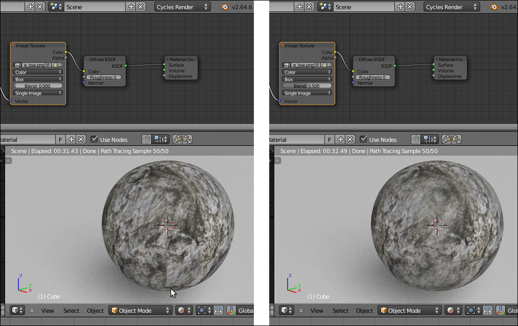
- Now add a ColorRamp node (press Shift + A and go to Convertor | ColorRamp) between the Image Texture node and the Diffuse shader. Set the interpolation to Ease, move the marker of the black color to the middle of the slider and the white marker to a quarter on the left of the slider:
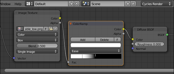
- Add a Bump node (press Shift + A and go to Vector | Bump), connect the Color output of the ColorRamp node to the Height input of the Bump node and the Normal output of the latter to the Normal input of the Diffuse shader. Detach the Color link from the Color input of the Diffuse shader and set the Bump strength to
0.500. - Add a Mix Shader node and a Glossy BSDF shader and connect them to be mixed with the Diffuse shader. Set the Glossy shader's Roughness value to
0.400and the Mix Shader factor to0.300. Connect the Normal output of the Bump node to the Normal socket of the Glossy shader: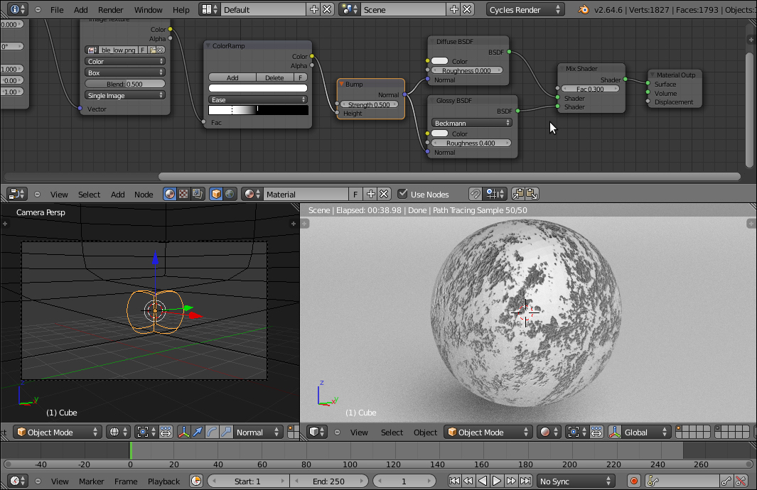
- Add a RGB node (press Shift + A and go to Input | RGB). Add a Mix node (press Shift + A and go to Color | Mix). Connect both the Color outputs of the RGB and Image Texture nodes to the Color1 and Color2 input sockets of the Mix node. Connect the Color output of the Mix node to the Color input sockets of the Diffuse and Glossy shaders.
- Click on the color slider of the RGB node and set these values: R 0.407, G 0.323, and B 0.293. Connect the Color output of the ColorRamp node to the Fac input of the Mix node.
- In the Texture Coordinate node, set the Y rotation angle to 20° and set the scale for all the three axes to 0.500:
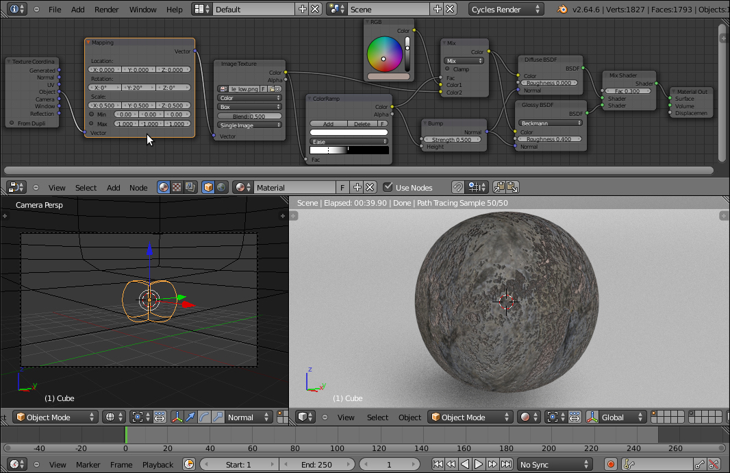
- As a last step (which is optional, but can improve the material), add a new Mix node (press Shift + A and go to Color | Mix). Set the Blend Type to Difference and drag it to be pasted between the ColorRamp and the first Mix node.
- Switch the ColorRamp output from the Color1 input to the Fac input of the Difference node, connect the RGB node output to the empty Color1 input and the Image Texture color output to the Color2 input.
- Change the Mix node Blend Type to Color, switch the Diffuse node output from the Fac to the Color2 input of the Color node and connect the color output of the Image Texture node to the Color1 input of the same Color node. You can let the Fac value of the Color node to
0.500. The more you increase this value, even to the maximum value of1.000, the more the color of the RGB node will influence the final result.
- Rename the material as
Rock_01(the numeration is because I assume that you are going to experiment with the several values producing more and different kind of rock materials). If you wish, model a very quick rock mesh, by sculpting or deforming the subdivided cube in proportional edit mode, and assign to it theRock_01material: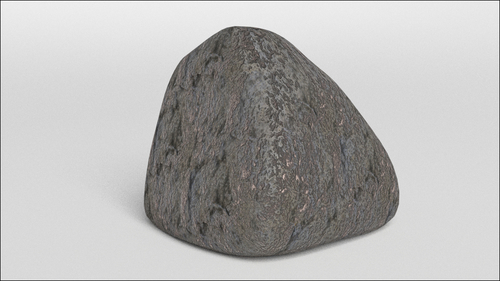
We have mapped a color rock image with the
Box option available in the Image Texture node (developed by the Mango Team for the "Tears Of Steel" production to quickly map objects without the need to unwrap them) and set the Blend factor to 0.500 to have smooth transitions at the corners.
First, we have applied the image map to the cube as color, to have a quick feedback. Thanks to the ColorRamp node, we have obtained the following goals:
- We have converted the color image to a gray-scale image, which is to be used for the bump
- By moving the color markers, we have remapped this value to reverse and increase the contrast (we could have obtained the same result by processing the color map in Gimp, for example, by desaturating it and playing with the Curve Tool).
This contrasted result has been applied as a bump map both on the Diffuse as well as on the Glossy shaders.
Then, we have mixed a brownish color (the RGB node) with the color output of the rock image. The contrasted values of the ColorRamp node have been used as a factor for the mixing of the colors, thereby giving more and nicer variations to the surface.
In the last optional step, we added more variations to the coloration by also calculating the "difference" between the image and the RGB color, with the contrasted gray-scale output of the ColorRamp node as blending factor, and we added it to the final result using the Color node.
We can also improve the "rocky" effect by adding displacement to the geometry. Unlike bump or normal effects on the mesh surface, which are just optical illusions giving the impression of a perturbed mesh surface, displacement is an actual deformation of the mesh based on the gray-scale values of a texture.
At least in this case, there is no need for a precise correspondence between the already textured surface and the displacement, because it would be barely noticeable, so we can use object modifiers to obtain a fast but effective result:
- Starting from the
Rock_01file we just created, select the cube and go to the Object Modifier panel. In the Subdivision Surface modifier already assigned, set the Subdivisions levels for both View and Render to3. - Add a new Subdivision Surface modifier and set its levels to
4. - Now add a Displace modifier and click on the Show textures in texture tab button, the last button to the right of the Texture slot. This switches the Textures window on from where we can click on New and then change the default Clouds texture with a Voronoi texture. Set the Size value to
2.00and let the rest be unchanged. Go back to the Object Modifier window and set the modifier strength to0.300. - Add a new Displace modifier. Switch to the Textures window and assign a new texture. We will use the default Clouds texture now, but just change the Size value to
0.50and Depth value to8. Now, back at the modifiers, set the Strength value to0.350. - Add a last Displace modifier. In the Textures window, select a Noise texture and set the Strength value to
0.005. The following is what we come up with: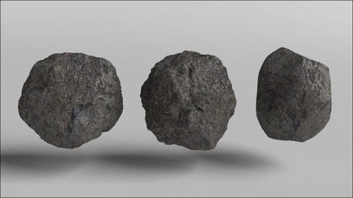
Of course, these are just basic values. However, you can change them and also play with different kinds of procedural textures to obtain several different rock shapes.
