Introduction to Rigging: Armatures and Bones
WHEN WE SEE CHARACTERS and objects moving in an animation movie, it doesn't mean they are all using an Armature, that is, it is not mandatory all objects have to pass the Rig process.
We may animate any kind of object by adding a couple of keyframes modifying its location over the scene and we will get our object going from point A to point B on the scene within a determined time frame.
There are different techniques in animation that we will cover later in this chapter, but rigging is one of the most important tasks in animation movies.
As we discussed in the previous chapter, a good model is necessary if we want to achieve good results, because the rigger will need to apply an Armature, or skeleton that will be manipulated later by the animation crew so they are able to apply deformations resulting in poses making the final animation possible.
The complexity of a very good rig varies depending on the project and the final result expected. In very important projects, the number of bones that compose the skeleton of the main characters is overwhelming. We must mention here that the rigging team usually shows the final skeleton with the minimum manipulators needed, keeping those secondary bones or helpers hidden in layers.
A very good rigging not only consists of using the necessary bones and applying the right constraints but also organize it in layers, keeping it clean, and adding widgets and manipulators to keep it as organized as possible as shown in Figure 9.1.
The final rigging must be structured and organized in layers so that we can show or hide bones, widgets, and manipulators easily, avoiding chaos in the animation process.
The rigger job is related to very technical aspects and closely related to maths and programming because many times the rigger must resolve artifacts issues or any other kind of malfunction in the model and it's there where the rigger starts a very technical process of research.
In the same way, an advanced knowledge of constraints is basic for the development of this job because that will determine the workflow, not only for the rigger but also for the final result.
Many times, we reuse armatures and it's very important we keep this in mind when we need to use similar armatures on the same type of characters, for example, in a group scene as shown in Figure 9.2.

Scene of the Pixar's Bugs movie where we can think about the reuse of the armatures on a group of similar characters, instead of developing a specific one for each character.
In a typical work day of a studio's rigger, we find the following tasks to be done:
- The rigger gets the model.
- The rigger starts a study about how to develop the armature, probably on paper first.
- When the rigger has anything to start with, the first bones are generated, making children and parents follow a naming convention.
- The rigger adapts bones to the mesh by making sure the bones are aligned with the edges and vertices of the model so that the deformations are smooth.
- The rigger applies constraints like copy location, rotation or scale, IK, track, or any other needed to get the bone working as expected.
- The rigger applies the skeleton to the model and redefines to avoid possible issues, usually using Weight Paint.
- The rigger organizes different groups of bones using colors and layers.
- The rigger makes widgets for easy manipulation.
Next, we will see in depth how to work with Armatures in Blender. Without doubt, work in Blender on our own skeleton is bound to be an exciting experience, and we will see how Blender's versatility suits any animation studio requirements for this kind of job.
9.1 The Armature Object
As discussed, the Armature object is like any other kind of object, say mesh, lamp, or empty, for example. Like them, the object Armature shares some common properties with other Blender objects. To name some examples, it has a center and a determined location and rotation or scale properties that may be modified. To modify, they should be in Edit Mode, might be reused and linked in different scenes or files, and might be animated like any other Blender object.
At this point, we must understand that when we say that it might be animated like any other Blender object we refer to the set of bones forming the armature like unique object. In order to use the armature and make the poses manipulating the bones, we must be in Pose Mode.
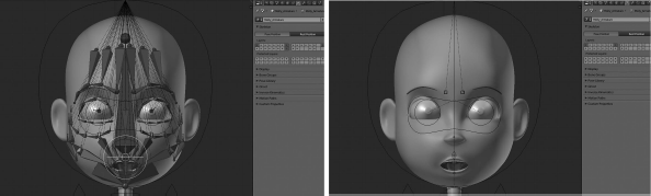
When a rigger makes an armature, he is making his first pose. That means every time we edit the armature in Edit mode we are modifying the so-called rest position or default position of the armature as shown in Figure 9.3.

When we are making the armature in Edit Mode, we are modifying the so-called rest position. In the picture, we see that position by default in Pose Mode.
We can access the Armature properties panel once we get it selected and we click on the Armature context icon within the Properties editor as shown in Figure 9.4, where we will see different panels to manipulate our Armature properties like apply name, manage layers, type of armature to show, or a library with poses and groups of bones.
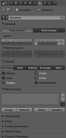
Properties of the Armature object are located in the Properties editor once we click the Armature context button.
Let's see the panels that show the properties of the object Armature:
- Armature name: We can apply a custom name to our Armature by editing this input button. If we have some armatures in our scene, we are able to select the using the Outliner editor or using the small button on the left of the previous input button that will drop down a list with all available armatures in the scene.
- Skeleton: In this panel, we might adapt our armature to different and useful options. We first tell Blender if we want our armature in Pose Position or Rest Position. That is the default and original position of the armature. In the same way, we can move and organize the bones in different layers, allowing a clear visualization and a better organized project. This option is specially useful, to organize bones depending on their nature, for example, widgets for head or arms, helpers, IK layers, drivers, and soon.
- Display: We can select how we want Blender to show the armature, specifically the type of figure representing bones. We also can filter to show names, axes, shapes, colors, x-ray, and so on. The available figures are Octahedral, Stick, B-Bone, Envelope, or Wire. Each one has its pros and cons, and the decision about taking one over the rest is up to the rigger depending on his preferences and needs.
- Bone Groups: A very important property helping riggers in their work is the separation of bones into different groups and apply different colors to these groups. This will make the armature comprehensible not only for the rigger himself but also the animation crew. An example could be a group of bones called deformGroup where we can place all those bones deforming the mesh and apply a black color to that group. We might add another group for IKGroup where we could place all those bones related to inverse kinematics and apply a yellow color to that group. In this way, the rigger's work is pretty dynamic because we can see which kind of bones we are manipulating with a single overview, in which group the bone is placed, and its nature and its purpose.
- Pose Library: Blender allows us to store different poses in something called Pose Library; we can use any of the stored poses later in production. To add or delete poses from that library is really easy from this panel, in the same way as renaming poses. Blender also allows us to add more than a single library. That is specially useful to organize our libraries as different groups of poses, for example, a library called Dancing and another called Running.
- Inverse Kinematics: This determines the type of IK solver used in the animation. Available options are Standard and iTaSC.
- Motion Paths: We can use it to enable the option to visualize the motion paths our animated objects leave when they are animated. We can select the type of range between Around Frame and In Range. We can display both paths depending on the selected range or range of frames from the current one.
9.2 Bones
As discussed earlier, the bones are the elements that compose the armature object. This means that adding a single bone to our characters implies creating an armature object, even if it is composed of a single bone. Bones may be represented in diverse ways as we pointed out in Section 9.1. The Octahedral type is used by default, and we will use it as the basis to continue with this rigging adventure (Figure 9.5).
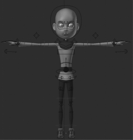
Widgets are really useful for the animation crew. Using these widgets, there is no need to visualize complex armatures. It is kind of what you see is what you need paradigm.
To manipulate bones correctly so we can complete our armature successfully we should know the elements that the bones are composed of.
- Start point: This is also called root or head.
- Body: It's the bone's core itself and may be modified and adapted in location, rotation, and scale.
- End point: This is also called tip or tail.
At this point, there is something we need to know. Both the root and the tip may be manipulated independently, but they only allow modification of their location property. They can't be resized or rotated independently. On the other hand, the bone's body allows it to be escalated, rotated, or translated. It's also important to understand that we can extrude bones from an existing one and we must do this from the root or the tip of the previous bone.
It's important to check from where we are going to extrude new bones because the behavior might vary depending on whether it extrudes from root or tip. Usually, in a lot of riggings, the extruding action is done from the tip, because this creates a logical structure for the skeleton. But, we must remember that sometimes it's not useful for our purpose and then we need to extrude from root. It's up to us depending on our needs (Figure 9.6).
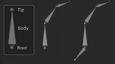
Bones' structure represented on the left, where we can see bones' elements like tip, body, and root. The two figures on the right represent an extruding exercise, one from the tip (middle) and one from the root (right).
We can access the bones' properties panels by selecting the Armature context with the bone-like button from the Properties editor. We will see all available options automatically where we might modify our bones' properties with such a transformation, lock axis, add relationships to groups, modify deformations, or change appearance and display (Figure 9.7).
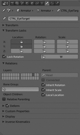
We can access the bones' properties panels from the Armature's context by clicking the bone-like icon in the Properties editor.
Let's see the panels that the bones' properties provide:
- Bone Name: We can apply a name to our bones from this input. During the rigging process, it's very important to follow a naming convention helping to locate bones in the armature tree. This keeps the structure clean and organized. By default, Blender adds the bones' name automatically, something like Bone.001 that in very large projects like the big animation studios ones, are not really useful, in fact, worse because it delays production. We will see later a proposal for naming conventions.
- Transform: In Edit mode, we can manage the head, tail, and roll values from this panel. We can also lock the bone properties by enabling the Lock option.
- Relations: We can move our bones to different layers. We can also modify their relationship or assign a new parent, connect to that parent, or make them independent. Here, we have the useful feature to add our bones to different predefined groups.
- Deform: If this option is enabled, we are allowing our bones to deform geometry so we can apply values to factors like Envelope, or add segments and modify the influence ratio.
- Display: This panel contains all options to modify our bones the way we want to see them. We can show or hide bones, like we can do in the Outliner editor. A very important property in this panel is that we can apply a custom widget. This means that we are able to apply any other shape to the bone so that bone is displayed with that shape instead of the predefined bone shape like Octahedral, Stick, etc. This is really useful to create a widgets as manipulators that will help the animation crew in the animation process.
- Inverse Kinematics: Once we know a lot of armatures and bones, we notice a very interesting property of the bones. They are composed of small segments making the bone very flexible in case we need that property. By default, a bone is composed of a single segment but we can modify that, as discussed to apply some flexibility to that bone. This allows us to play with the number of bones we need to introduce in our characters.
9.2.1 Bones' Segments
In cartoon animations, it's very easy to see some characters requiring this kind of property because in this animation style it's common to use the stretch and bounce resource by increasing the number of segments the bone is composed of. This technique comes from the first Walt Disney animations and you can see what we mean in any of the classical cartoons of that company.
We see an example in Figure 9.8. Notice the difference between add bones with a single segment and that when we raise the number of those segments. We notice, in the armature of the right, that the flexibility support when we increase the number of segments in each bone. Specifically, we can use four segments per bone.
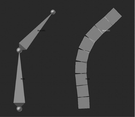
In the picture, the armature on the left uses bones with a single segment by default. On the right, the armature uses four segments per bone, so deformation and flexibility of the object are smooth.
This will allow us to deform our characters and objects smoothly, avoiding strange artifacts and reducing rigidity, making it look natural. If we need a practical example where the segments are really necessary, we could talk about the RAT bProficiency project where the segments are really necessary when we want to apply the rig to the character's tail. This element should be very flexible and should avoid any rigidity. We can solve that by adding as many bones as needed but we could be making the skeleton overly complex with the attached risk of making it less organized than expected. The perfect solution for this trouble is to add some bones to that character's tail and then apply the segments solution by increasing the number of segments per bone. In doing this, we make the character's tail deform smoothly and we have a clean and organized skeleton with less bones and better results as shown in Figure 9.9.
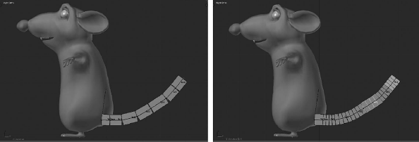
The picture on the left represents the number of bones added to the solution. The picture on the right represents the number of segments added to the solution. On the right, we increase the number of segments per bone and the result looks smooth and clever.
We can do this from the panel Deform within the Bones' properties context. We must mention here that working with B-bones we must be careful with the mode we are working on. If we work with B-bones in Edit mode, these bones will be displayed as any other bone in edit mode, that is like, rigid elements. However, if we switch to Object mode, we will notice that our bones are displayed as segments and how Blender automatically calculates the deform curve depending on our bones' properties. Finally, if we are in Pose mode, we can deform and apply poses.
This means that segments are always present, we can see them even at a glance. The elements we should take into consideration depend on the specific cases, so the riggers must be careful with those elements requiring this solution.
9.2.2 Bones' Influence
Bones are grouped to complete the whole armature as we already know, but they should be applied to the object we want to deform in the manner that objects deform their original shape as we move bones. The principle of applying the skeleton to the object so it's affected by the change is called Skinning and we have different methods to apply it in Blender. We'll see now one that is commonly used in the studios.
To let our characters or objects to be deformed by our bones, we must link our bones to those objects, that is, basically, link our Armature. Blender needs to be able to recognize that a determined object has linked an armature and the bones composed in that armature are then allowed to deform our object depending on their influence.
Blender supports a couple of methods to link an armature to our objects. One is to add an Armature modifier to our object. The other one is to create a parent–child relationship between both object and armature.
We reckon the modifier Armature as the most interesting one to illustrate Blender skills. First, once we have our object and our armature, we must be sure to be in Object mode, then we select our object, and we go tot he Modifiers context by clicking on the wrench-like icon in the Properties editor. There we find the Armature modifier and selecting it we have Blender showing all available properties for that context. We have some very interesting panels there; let's check the most interesting ones:
- Modifier name: We supply a modifier name here, in our case the object that represents our armature. As discussed earlier, a single object might contain different armatures, so it's important to use a naming convention.
- Display type: This is used as a filter where we enable the option to show or hide our modifier in different states. The available options are Use modifier during render, Display modifier in realtime, and Use modifier while in Edit mode.
- Move modifier panel: These are basically two arrows, up and down, to move our modifier around others. It's important to take into consideration the order of the modifiers. Because Blender takes care of the modifier position in the tree, results may vary depending on that position. For example, applying a Mirror first and a Subdivision Surface later ends in a different result compared to applying a Subdivision Surface first and a Mirror later.
- Remove modifier: This deletes or unlinks the modifier and the object. Basically, it breaks the relationship between both elements.
- Object: This refers to the name we apply to our Armature as object. Here, we will tell Blender the object that should be used as armature is our recently created Armature.
- Bind To: This is a method where we can bind the armature to any provided mesh and this can be done by enabling or disabling Vertex Groups or Bone Envelopes.
- Vertex Group name: We might apply our modifier to vertices groups in specific objects instead of on the whole object itself. Sometimes, this is used to apply some effects to specific parts of meshes, so the modifier doesn't affect the rest of the vertices.
The second option is to apply our armature by establishing a parent–child relationship between object and armature. For that, we need to select our object in Object mode and pressing the Shift key we select our Armature. Then, we press Ctrl+P keys to use the parent feature.
The Set Parent pop-up menu appears asking us about the type of relationship we want to apply to both objects as shown in Figure 9.10, where we can select Armature Deform with envelope, for example.
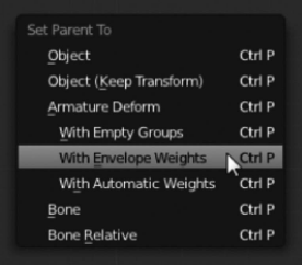
The Set Parent To pop-up menu allows us to select the type of relationship between two objects. Here, we select Armature Deform to make the armature deform the object.
Then, our armature is automatically linked to the object and each kind of deformation of our bones will affect that object. It must be said that the skinning method by applying a modifier Armature is very interesting and gives us more control over our rig. So, the parent–child method can be used for small tasks by animation studios like an auxiliary method.
As we can see, an armature is composed of a bone's chain that might or might not be connected between them. This implies that bones might or might not share contact between them. As shown in Figure 9.11, bones that keep contact in the parent–child relationship also share location for root and tip. That is, the tip for one bone is in the same place as the root of the other one. On the other hand, we have bones that have a parent–child relationship even when they have no contact between them. Instead, we see a dotted line between the tip of one bone and the root of the other one.

We see that Bone.001 is directly connected to its parent in the picture on the left. But the bone Bone.001.L is not directly connected showing a dotted line in the right picture.
Sometimes, it's not necessary to keep the direct contact between bones; sometimes it's even necessary to break this contact, so we can enable or disable that with the Connected option located in the Relations panel.
In both cases, whether the bone is connected or not, we are able to tell Blender to avoid this bone inheriting the parent's rotation or scale from the same Relations panel. Disabling these options we make the child bone keep its own rotation or scale. In some animation styles, this is really important and to know our bones' chain offers these possibilities is important to understand the complexity of the rigging process.
We have seen how to create a simple bones' chain and how each bone keeps a parent–child relationship. There are some motivations in the rigging process to modify this relationship. This means that sometimes we require the bones added to the chain to be able to change their relationship and so we have to assign another parent to them. This is easily done in Blender and we have a few methods to do it.
We can use the Relations panel that we are familiar with. For that, in Edit mode, we select the child bone and then we insert the new parent bone name in the Parent input field.
Another way is by using keyboard shortcuts. In the same way we talked about linking objects and armatures, we should select the child bone in Edit mode, then by pressing Shift key we select the bone we want to be parent. To apply the relationship, we press Ctrl+P and then select if we want this relationship to be Connected or Keep Offset (disconnected) as shown in Figure 9.12.
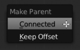
Make Parent float panel. Here, we could modify the child–parent relationship and the option to make it connected or keep the offset between both bones.
As shown in Figure 9.13, now our bone displays an influence range that says the range could affect in a possible deformation. We can scale that influence range from the Pose mode. We select the bone and then press Alt+S.
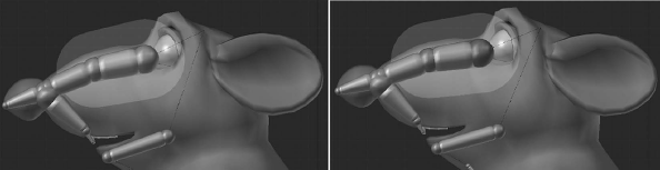
We can visualize Envelope mode so we know the influence range. That influcence range might be modified in Pose Mode, as seen in the left image. On the other hand, we can scale the tip and the root so the influence is proportionally scaled too like in the image on the right.
It's important to know that if we are in Edit mode and the display type is Envelope, we can select the tip or root of our bone and scale so the influence range is proportionally scaled as shown in Figure 9.13.