
Chapter 12. The Generic Access Profile
It is no coincidence that in no known language does the phrase “As pretty as an Airport” appear.
—Douglas Adams
The final part of the core specification is the Generic Access Profile (GAP). This defines how devices can discover and connect with one another and how they bond. It also describes how devices can be broadcasters and observers and, as such, transfer data without being in a connection. Finally, it defines how the different types of addresses can be used to allow private and resolvable addresses.
12.1. Background
One of the most important things to understand with Bluetooth low energy is how two devices first find one another, work out what they can do with one another, and how they can find and connect with one another repeatedly. This is really what GAP defines. To illustrate how Bluetooth low energy works, let’s consider a typical user scenario:
A user has just returned home from the store from which she has just purchased a new heart-rate belt. She already has a low energy–enabled phone and wants to connect the heart-rate belt to the phone. She has been buying a lot of low energy devices recently; the list includes a low energy–enabled television with remote control, a low energy lighting system, and, of course, low energy sensors in her computer, shoes, and watch. How does she configure the heart-rate belt to work with her phone?
The user opens the heart-rate belt box and reads the instruction leaflet that tells her to remove the plastic tab from the heart-rate belt to turn the device on. It then instructs her to discover the heart-rate belt. On her phone, she accesses the Bluetooth menu, taps the “Add Devices” button, and then watches as a number of devices appear on the screen.
At the top of the list of devices is the heart-rate belt she just purchased along with an icon of a heart-rate belt. She selects the heart-rate belt, and the phone moves to its application store and displays a list of applications that work with this device. Some applications are free, some cost money, and some are from the same brand as the heart-rate belt. She selects an application and installs it on the phone. A few seconds later, the application is running and displaying heart-rate information on the screen. The user goes out for a run to test the application.
The next day, the user puts on the heart-rate belt again and starts the application she downloaded yesterday. Again, the heart-rate information is displayed on the screen. It’s almost like magic—she simply uses the application, and the device works.
A few days later, one of the user’s friends recommends a different application that he downloaded for his own heart-rate belt. She goes to the application store, searches for this application, downloads it, and then runs it. The application again displays the heart-rate information, but now also includes additional information about how hard the user is working out. The application is using the same heart-rate information from the belt, but this time it’s using the data in a different way.
This example shows how a user can simply begin by using a Bluetooth low energy device, and how the flexibility of Bluetooth low energy services means that they are not tied to a single application to use that device.
12.1.1. Initial Discovery
To discover a device, you must scan for devices that advertise. Advertising devices transmit packets to any scanning devices by using a many-to-many topology. The problem with this is that every device that is connectable, but not necessarily discoverable, will be scanned. To solve this, in addition to data, some flags are also broadcast that reveal whether the device is discoverable or connectable.
There are two types of discoverability. The first type is used by devices that are “limited-discoverable.” This is used by devices that have just been made discoverable on a temporary basis. For example, the first time a device is powered on, it would be limited-discoverable, or if the device had a button that allowed it to be discoverable temporarily. A device is not allowed to remain in the limited-discoverable mode for very long. This is because limited-discoverable mode is intended to allow devices to stand out from the crowd of general-discoverable devices. If devices stayed limited-discoverable for a long time, they would not stand out. Therefore, a device can only be limited-discoverable for about 30 seconds.
The second type is used by devices that are “general-discoverable.” This is used by devices that are discoverable but have not been recently engaged in interaction. For example, a computer that is discoverable, such that other devices can find and connect to it, but has not recently had this discoverability turned on, would be generally discoverable. A device that is searching for other devices would typically place generally discoverable devices lower down the list of found devices because these are probably not going to be as immediately important to the user as those limited-discoverable devices are now.
Determining device discoverability is the combination of scanning for all devices and filtering on the discoverable flags that each of these devices is broadcasting. It is also possible to use additional filters when presenting the list of devices to a user. For example, the proximity of the device can be used to present the devices that are closer to the searching devices at the top of the list and those that are farther away at the bottom of the list. To do this, the transmit power at which the advertising packets are transmitted is compared with the received signal strength to calculate the path loss of the communication. Devices with a smaller path loss will likely be closer than devices with a larger path loss.
Another possible form of filtering involves using the service information in advertising data to segregate based on what a devices does. For example, if the user is looking for a heart-rate belt, then the fact that one device in the area supports this particular service probably indicates that this is the device with which the user wants to connect. There are two types of service information that a device can expose: a device can expose a list of the services that it has implemented, and a device can expose a list of services that it would like a peer device to support.
Therefore, with nondiscoverable devices, limited-discoverable devices, general-discoverable devices, path loss range filtering, and service-based filtering, an intuitive interface can be made for the user. If the user interacts with a device, it appears at the top of the list; if he moves the device closer, it appears nearer the top of the list; if the device supports the services that are being searched for, they will appear closer to the top of the list. A user just performs the search, looks at the item at the top of the list, and, with high probability, connects to this correct device.
One little wrinkle in the device discovery procedure is name discovery. Users don’t like to look at hexadecimal 48-bit numbers; instead, they prefer to look at user readable and understandable names. To allow every device to have a name, the GAP defines a characteristic that exposes the device name. The device name can also be included in the advertising data or the scan response data for devices.
To obtain the scan response data, active scanning needs to be used. Therefore, when discovering devices to display names on the screen, active scanning is typically required. This is because the device name is static data that would normally be included in the scan response data and not the advertising data. However, some devices have so much information they need to broadcast that they are unable to include the complete device name in the advertising or scan response data; instead, they include just part of the name or none of the name.
To obtain the complete device name in this situation, a connection must be made with this device and the device name read. Thankfully, the device name has the well-known characteristic type of “Device Name,” which you can read by using the simple attribute protocol Read By Type Request.
12.1.2. Establishing the Initial Connection
Once the list of devices has been found and a device has been selected, the next step is the initial creation of a connection to the device. This initial connection is performed by initiating a connection to the same device address that was found from the advertising packets. Once the devices are connected, the connecting device performs either an exhaustive enumeration for all the services and characteristics of that device, or it looks only for the service or services that it is interested in, and the characteristics of those services.
For example, a phone or computer that has an application store would enumerate all the services that the device exposes. This service information can then be sent to the application store, and any applications in that store that support those services would be presented to the user. So, instead of the user having to use the application that came with a device, an ecosystem of applications becomes available. Some would be free, some would cost money, some would be made by the manufacturer of the device, and some would be from independent software companies.
The alternative method is that the device only performs service discovery for one or possibly a very limited list of services. For example, a television that is connected to a remote control would only search for the human interface device service and possibly the battery service, but nothing else. This means that even if the device supported more services than these two, the television would never even perform service discovery on them. This method would typically be used by devices that have a limited user interface or by devices that are connecting to peripherals that only use a very simple set of functionality.
The result of service discovery is a list of those services that a device exposes. The client can then use these services. In the application store model, it is the application that takes the next step of characteristic discovery and configuration. Characteristic discovery is just like service discovery in that a device can either enumerate all the characteristics within a service or just use the well-known characteristics that it knows a service must expose. For example, the battery service must expose the battery level characteristic. So, if it doesn’t need to discover any characteristics within the battery service, a client can read the battery level characteristic directly.
12.1.3. Service Characterization
For a heart-rate belt, the characteristic discovery and configuration might be a little more elaborate. For example, the heart-rate service might expose just the heart rate, or an aggregation of the heart rate and the time intervals between heartbeats, or just the time interval between heartbeats. It can also expose other information that it has calculated from the heart-rate sensor. A client can pick and choose which characteristics to read. Some clients might only be interested in the heart-rate value, whereas others might want to read all the information.
For the efficient transfer of data between devices, notifications or indications should be used. To configure the characteristics for which a client wants to receive notifications or indications, the client must write the client characteristic configuration descriptor. This descriptor enables the required functionality. The device then starts sending these notifications or indications whenever necessary. For the heart-rate example, a client might configure the heart-rate value to be notified, and for that service, the value would be notified once each second, even if the heart rate doesn’t change. For other services, the time interval can be more flexible. The battery service, for example, might only notify a value when the value changes.
Thus, the application can configure the set of characteristics to be notified or indicated and then wait until the service sends this data through. This means that even if the user changes the heart-rate application, the new application will continue to receive the heart-rate notifications that were previously configured.
12.1.4. Long-Term Relationships
Most of the time, a peripheral is associated with a single central device. Your proximity tag is associated with your phone; your keyboard with your computer; your garage door opener with your garage door. When one device is associated with another, they are are said to be bonded. Bonding is a two-step process by which two devices that barely know one another authenticate themselves and share secrets.
For bonding to be successful, both devices also need to be configured to be bondable. A device that is not bondable—perhaps because it is already bonded with another device and can only manage a single bond at a time—doesn’t need to advertise that it is bondable.
When both devices are bondable and one of these devices wants to bond, the first step of the bonding process has started. After this, the input and output capabilities of the two devices are exchanged, an authentication algorithm is chosen based on these capabilities, and the devices authenticate one another. This results in an STK that is used to encrypt the link (for more information about this, go to Chapter 11, Security, Section 11.1.7.2).
With the link now encrypted, the second step of the bonding process can be performed. This step involves exchanging shared secrets that can be used when reconnecting to the same device. These shared secrets are typically keys that have various uses: a Long-Term Key (LTK) for encrypting subsequent connections, an Identity Resolving Key (IRK) for resolving private addresses, a Connection Signature Resolving Key (CSRK) for checking the signature of signed attribute protocol commands, as well as the distribution of some identification information sent by the slave to the master so that the slave doesn’t have to store the information.
12.1.5. Reconnections
Sometimes, devices will discontinue a connection. This might be because they’ve already sent everything they needed to send and don’t want to waste energy maintaining a connection. A light switch will create a connection, send the “turn on the light” command, and then quickly disconnect. Sometimes, the connections might be maintained for significantly longer periods of time. For example, a keyboard might remain connected with a computer until the computer is turned off, at which point, it disconnects. When the computer is turned back on again, it needs to reconnect to the keyboard.
Reconnections are both easy and hard. In Bluetooth low energy, all devices that want to be slaves in a reconnected connection need to be advertising by using connectable advertising events. It might not be discoverable, or it might be either limited or general-discoverable, or it might not allow connections from any device. Also, for a device to connect to an advertising device, the master must scan or initiate a connection to the device with the particular address that is advertising. This means that the reconnecting device must be in the white list of the scanning or the initiating device if white lists are being used (for more information about white lists, go to Chapter 8, The Host/Controller Interface, Section 8.4.10).
12.1.6. Private Addresses
Some complications are introduced if the device that is advertising is using private addresses. A private address is a random address that changes periodically, for instance, once every 15 minutes. This means that even if you discovered a device that is advertising now, you will not be able to determine if that same device is around in 20 minutes’ time, because it might be using a different address. This can at first appear to be an impossible problem to solve.
The solution to this problem is a three-step process. The first step is to save an IRK during bonding; the second is to use this key to generate a resolvable private address; and finally, the master must scan for all devices and resolve these private addresses by using all the IRKs and only connect to devices that it believes it has identified.
A resolvable private address is a type of random address that comprises three parts. The first part is a set pattern of two bits to identify that this random address is a resolvable private address. This reduces the computational load on the scanning device so that it only attempts to resolve private addresses on resolvable private addresses. The second part is a 22-bit random number. The third part is a hash of the random number with the IRK that was shared during bonding.
The combination of the random number and the IRK means that each private-addressed device effectively has four million possible addresses that fingerprint it.
A master that wants to reconnect to a slave device that is using private addresses must therefore take each resolvable private address that it scans, check with each and every IRK for each device that it knows could be using private addresses, and then compute the hash value that would have been used for each of these devices, given the random number. If this hash value matches the value used in the resolvable address, then there is a fairly high probability that this is the device identified by that key.
This is not absolutely certain. It’s possible that another device with a different IRK with the same random number generates exactly the same hash value. However, a quick connection and encryption can quickly check that this is the correct device. The IRK and the LTK used for encryption or the CSRK used for signature authentication will be different for each of these devices, which can quickly confirm that this is either the right device or the low probability that a duplicated hash value has happened and it is the wrong device.
Private addresses have some disadvantages. The biggest one is that the host of the master must perform brute-force checking of each and every IRK for each resolvable private address that it receives. If that host knows many private devices, this could take some time. The HCI Encrypt command is very useful in this instance, especially if the host has few computation resources available.
Another disadvantage is that white lists cannot be used to make connections easily. The only way to connect to private devices is to first scan for the resolvable private addresses, compute if this is a private address of one of the devices to be connected to, and then connect to it manually. This increases the power consumed by the host because the host must perform many computations to resolve the addresses.
12.2. GAP Roles
There are four GAP roles defined for a Bluetooth low energy device:
• Broadcaster
• Observer
• Peripheral
• Central
A broadcaster is a device that sends advertising packets. Typically, this is used to broadcast some data from a service to other devices that happen to be in an observer role. A broadcast must have a transmitter but does not need a receiver. A broadcast-only device, therefore, only needs a transmitter.
An observer is a device that scans for broadcasters and reports this information to an application. An observer must have a receiver; it can also optionally have a transmitter.
A peripheral is a device that advertises by using connectable advertising packets. As such, it becomes a slave once connected. A peripheral needs to have both a transmitter and a receiver.
A central is a device that initiates connections to peripherals. As such, it becomes a master when connected. Just like a peripheral, a central needs to have both a transmitter and a receiver.
A device can support multiple GAP roles at the same time. For example, a device can be a broadcaster and a peripheral at the same time.
12.3. Modes and Procedures
Within GAP, there are two basic concepts that are used to describe how a device behaves. These are modes and procedures.
When a device is configured to behave in a certain manner for a long time, this is known as a mode. If a device is configured to perform a single action that has a finite time period over which this behavior will occur, this is called a procedure.
For example, when a device is broadcasting, this is called “broadcast mode.” Broadcasting typically lasts a long time; perhaps that is the single purpose of the device. When a device is looking for broadcasters, this is called the “observation procedure.” Observations typically occur for a very short period of time to build a user interface or find specific information that is needed.
Within GAP, the following modes are defined:
• Broadcast mode
• Nondiscoverable mode
• Limited-discoverable mode
• General-discoverable mode
• Nonconnectable mode
• Directed-connectable mode
• Undirected-connectable mode
• Nonbondable mode
• Bondable mode
Within GAP, the following procedures are defined:
• Observation procedure
• Limited-discovery procedure
• General-discovery procedure
• Name-discovery procedure
• Auto-connection establishment procedure
• General-connection establishment procedure
• Selective-connection establishment procedure
• Direct-connection establishment procedure
• Connection parameter update procedure
• Terminate connection procedure
• Bonding procedure
To understand GAP is therefore to understand how these modes and procedures interact with one another. For example, the broadcasting mode and observation procedure can be logically combined to allow observations of broadcasters.
12.3.1. Broadcast Mode and Observation Procedure
When a device is in broadcast mode, it is using the Link Layer advertising channels and packets to transmit advertising data. This broadcast data can be observed by devices by using the observation procedure.
When broadcasting, the advertising data must be formatted correctly, as described in Section 12.5.
It should be noted that some devices might have only a transmitter and are therefore broadcast-only devices. For these devices, it would not generally be possible to use private addresses or signed data in the broadcast data. Both of these require knowledge of keys that are distributed during the bonding procedure that require a connection, which require both transmitter and a receiver. Of course, if these keys could be distributed out of band, then they could still be used; however, there is no standard defined method for this to occur.
12.3.2. Discoverability
In GAP, only devices operating in the peripheral role are discoverable. Devices that are trying to discover these devices will be in the central role.
A peripheral device can be in one of three different modes used for discoverability: nondiscoverable mode, limited-discoverable mode, and general-discoverable mode. Discoverability, in the context of GAP, does not mean that a device is advertising, but that the device is discoverable by a user interface on a peer device. A device can transmit advertising packets without being discoverable, as understood by GAP.
Therefore, it’s necessary to include discoverability information as part of the advertising data for devices to be discoverable in the context of GAP. This differentiates them from the devices that are advertising or broadcasting data that are not discoverable. To do this, the Flags AD information (see Section 12.5.1) includes two bits that are used to determine if a device is in nondiscoverable mode, limited-discoverable mode, or general-discoverable mode.
12.3.2.1. Nondiscoverable Mode
A peripheral that is in nondiscoverable mode cannot set either the limited-discoverable mode or general-discoverable mode bits in the Flags AD information. If no other bits in the flags information are set, then the Flags AD does not have to be included in the advertising data. Nondiscoverable mode is the default discoverable mode; therefore, the host must command a change from this default to one of the other discoverable modes.
12.3.2.2. Limited-Discoverable Mode
A peripheral that is in limited-discoverable mode sets the limited-discoverable mode bit and clears the general-discoverable mode bit in the Flags AD. Limited-discoverable mode is used by a device with which the user has recently interacted, for example, the user just turned the device on for the first time or pressed the connect button, or the user just made the device discoverable in some user interface.
Limited-discoverable mode is only allowed to be used for approximately 30 seconds. This means that if another device finds a limited-discoverable device, it can be fairly certain that this is a peripheral with which the user has very recently interacted. Therefore, this device is most likely to be the one to which the user is trying to connect at this moment.
Because limited-discoverable mode is primarily designed for devices that are trying to be discovered and enter a connection, it is highly recommended to also include the following useful information in the advertising data that will help build the user interface:
• Tx Power Level AD to allow sorting of devices found by path loss and therefore range
• Local Name AD to allow the name of the device to be displayed
• Service AD to allow filtering based on what the device supports
Limited-discoverable devices should advertise at a reasonable advertising interval to both allow the user interfaces to be populated quickly and also to reduce the time required by the master device for scanning for Bluetooth low energy devices. The recommended interval should be somewhere between 250 milliseconds and 500 milliseconds. Obviously, a device that is discoverable and wants to connect should allow connections from any device, and, as a result, white lists would not be used.
12.3.2.3. General-Discoverable Mode
A peripheral that is in general-discoverable mode sets the general-discoverable-mode bit and clears the limited-discoverable mode bit in the Flags AD. A device uses general-discoverable mode when it wants to be discoverable.
When compared with limited-discoverable mode, general-discoverable devices are very similar, except in the following ways:
• General-discoverable devices can be discoverable for an unlimited period of time; limited-discoverable mode has a 30-second maximum time limit.
• General-discoverable devices have a slower recommended advertising interval of between 1.28 seconds and 2.56 seconds; limited-discoverable devices are between 250 milliseconds and 500 milliseconds.
It should noted that general-discoverable devices will not be found very quickly. This is by design; it is always useful to populate a user interface with those devices that are in limited-discoverable mode first and then place those devices that are generally discoverable lower down the list.
The same transmit power-level information should still be included in the advertising data, along with the other user interface building information, to allow the priority sorting and filtering of the discoverable devices to be used by the connecting device.
12.3.2.4. Discoverable Procedures
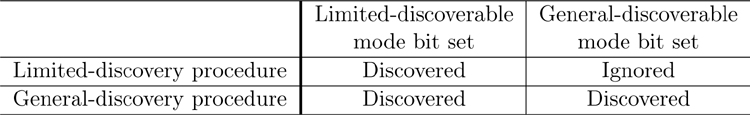
A central device that wants to find discoverable peripherals either uses the limited-discovery procedure or the general-discovery procedure. These two procedures are essentially identical except for filtering they perform based on the Flags AD information.
If there is no Flags AD information available in an advertising packet, or this information exists and neither the limited-discoverable mode bit nor the general-discoverable mode bit is set, then the advertiser is nondiscoverable and would not be discovered.
If the Flags AD information has the limited-discoverable mode bit set, the device is always discovered. This is true regardless of whether the limited-discovery procedure or the general-discovery procedure is used.
If the Flags AD information has the general-discoverable mode bit set, the peripheral is only discoverable when using the general-discovery procedure. These peripherals are not discovered by the limited-discovery procedure.
As shown in Table 12–1, the general-discovery procedure finds all discoverable peripherals regardless of whether they are limited or generally discoverable, whereas the limited-discovery procedure finds limited-discoverable peripherals.
12.3.3. Connectability
In GAP, only devices operating in the peripheral role use connectable modes. Devices that are trying to connect to these devices are in the central role and use connection establishment procedures.
As with discoverability, connectable peripherals can be in one of three modes: nonconnectable mode, directed-connectable mode, and undirected-connectable mode. However, connectability is more complex for the central device because there are four different connection establishment procedures: auto, general, selective, and direct.
From the GAP perspective, connectability is much easier to manage than discoverability. The Link Layer provides two types of connectable advertising packets: ADV_IND and ADV_DIRECT_IND; and two types of nonconnectable advertising packet types: ADV_NONCONN_IND and ADV_SCAN_IND. Thus, it’s always possible for the host to use the correct type of advertising packet based on the connectable mode it is using.
12.3.3.1. Nonconnectable Mode
A device that is in nonconnectable mode cannot use a connectable advertising packet type when it advertises. This means that it can only use the ADV_NONCONN_IND or ADV_SCAN_IND advertising packet types. This mode is the default mode, so the host must perform an action to make a peripheral device connectable.
12.3.3.2. Directed-Connectable Mode
A peripheral device that wants to connect very quickly to a central device uses the directed-connectable mode. This mode requires the use of the ADV_DIRECT_IND advertising packets and, as such, cannot be combined with the discoverable modes because these advertising packets have no host-generated advertising data.
Because directed advertising packets are sent very quickly, this mode can only be used for a maximum of 1.28 seconds, after which the controller will automatically stop advertising. The host should not immediately start directed-connectable mode after it has timed out because this can severely restrict the ability for other devices to broadcast, be discoverable, or establish connections. Therefore, it’s recommended that if directed-connectable mode times out, undirected-connectable mode should be the fall-back mode.
When using the ADV_DIRECT_IND advertising packets, both the current peripheral’s device address and the central’s device address are included in the packet. This means that the peripheral must have at least been connected with this device previously to know the device address. So, it’s assumed that this mode would only be used when devices are bonded.
12.3.3.3. Undirected-Connectable Mode
A peripheral device that is connectable but does not need to establish a connection very quickly or wants to be connectable while saving as much energy as possible would use the undirected-connectable mode. This mode requires the use of the ADV_IND advertising packets. Because ADV_IND advertising packets can include the Flags AD information, a device can be discoverable at the same time as being in undirected-connectable mode.
A peripheral stays in undirected-connectable mode until the host either moves to nonconnectable mode or a connection is established. Therefore, as soon as the new connection is terminated and the device wants to continue to be connectable, it will move back into the undirected-connectable mode again. Obviously, a device that was connectable but is now in a connection cannot still be connectable because this would require that the Link Layer support two connections in the slave role at the same time, and this is not a supported state for the Link Layer.
12.3.3.4. Auto-Connection Establishment Procedure
The auto-connection establishment procedure is used to initiate a connection to many devices at the same time. A typical user scenario for Bluetooth low energy is that a central’s host is bonded with a number of peripherals and it wants to establish a connection with each of these devices as soon as they start to advertise. For example, a central device might want the ability to establish a connection to any sensor device that has a new reading when the device starts advertising.
To allow a central device to make a connection to many devices at the same time, the host must first populate the white list with the set of devices that should be connected and then initiate a connection to the white list (for more information about white lists, go to Chapter 8, The Host/Controller Interface, Section 8.6.1). Typically, this would be the set of bonded devices about which the host is aware. Once one of these devices is found, because it is using directed-connectable mode or undirected-connectable mode, a connection is established. If other peripherals still need to be connected, the auto-connection establishment procedure would be restarted.
There are two downsides to this procedure: the procedure only has one common set of connection parameters that can be used, and this procedure cannot connect with devices that are using private addresses.
Because the connection parameters are determined by the central’s host when it initiates a connection to the white list, it is not possible to have different connection parameters for different peripherals. This, therefore, works best when the types of peripherals are reasonably similar, at least from a connection parameter point of view. Obviously, it is possible to change the connection parameters once the connection has been established. So, it might be necessary to initially use a fairly compromised set of connection parameters when using this procedure.
Private addresses also cause severe problems for this procedure. Because private addresses must be changed frequently and randomly to provide privacy, it is almost impossible to predict the private address that a device will be using at any given point in time. As a result, it’s not possible to use this procedure to connect to peripherals that are using private addresses.
12.3.3.5. General-Connection Establishment Procedure
In an attempt to solve the problems outlined in the preceding section, the general-connection establishment procedure does things slightly differently. Instead of using white lists, this procedure uses passive scanning to find all the devices that are advertising.
For devices that are using resolvable private addresses, these addresses are checked against all known IRKs for the devices to which the central devices want to connect. If the address resolves, the host stops scanning and uses the direct-connection establishment procedure by using the resolvable private address that it received.
Obviously, if a device address was received that was not a resolvable private address but is instead in the list of peripherals to which it wants to connect, it stops scanning and uses the same direct-connect establishment procedure by using the known device address.
The downside of this procedure is that there is a time gap between the host discovering that a device is advertising and the time when a direct connection establishment starts. This means that at a minimum, the connectable peripheral must send two connectable advertising packets before a connection can be established. This is a natural consequence of using private addresses.
This general-connection procedure also requires the processing of all advertising packets received by the controller in the host, even if the advertising packets are not connectable advertising packets or are not from devices that are interesting to the central device. This can require significantly more energy consumption in the host than the auto-connection establishment procedure.
12.3.3.6. Selective-Connection Establishment Procedure
The selective-connection establishment procedure is used to initiate a connection to many devices at the same time, but for which each device has different connection parameters. This solves the single-connection parameter problem from the auto-connection establishment procedure.
To perform the selective-connection establishment procedure, the host places the set of devices that are to be connected in the white list and then starts scanning by using this white list. This means that only peripheral devices that are in the white list and are advertising are passed up the host; all other devices that are advertising in the area are filtered out immediately by the controller.
When the host receives the advertising information from the controller for a device in the white list, it can first check that this device was using a connectable advertising packet type. If it was, the host stops scanning and uses the direct-connection establishment procedure to initiate a connection to this specific device. Because each peripheral might want to have a different set of connection parameters, the host can also look up the desired connection parameters for the peripheral that can be used by the direct-connection establishment procedure.
This has the same downside as the general-connection establishment procedure in that it takes a minimum of two advertising packets to establish a connection, but it solves the problem of having the same connection parameters as the auto-connection establishment procedure. Unfortunately, this does not solve the privacy issue of the auto-connection establishment procedure regarding the resolution of private addresses.
12.3.3.7. Direct-Connection Establishment Procedure
Many of the previous procedures reference the direct-connection establishment procedure. Basically, this procedure is used to establish a connection to a single, specific device by using a set of connection parameters.
It does not use the white list; instead, it initiates a connection directly to a single device address (for more information, go to Chapter 8, Section 8.6.2). This is why the general and selective-connection establishment procedures reuse this procedure to make the actual connection, once they have found the device address of the device that is advertising.
12.3.4. Bonding
Just like discoverability and connectability, bonding defines modes and procedures, except that there are only two modes: nonbondable mode and bondable mode; and just one procedure: the bonding procedure.
12.3.4.1. Nonbondable Mode
The default mode for devices is the nonbondable mode. This means that a device will not accept bonding at this time. No keys will be exchanged or stored by the device.
12.3.4.2. Bondable Mode
If a device wants to be bondable, then it is in bondable mode. When a device is in bondable mode, it will accept a bonding request from a peer device. To be in bondable mode, the bonding bit is set in the authentication requirements of the Pairing Request message during pairing (for more information on pairing, go to Chapter 11, Security, Section 11.2.2). If possible, the device exchanges security keys and stores them if necessary.
12.3.4.3. Bondable Procedure
If a device wants to bond with a device it believes is bondable, it uses the bondable procedure. When using the bondable procedure, the device initiates pairing with the same bonding bit set in the authentication requirements of the Pairing Request message.
Therefore, for bonding to work, the device that uses the bondable procedure initiates pairing with the bonding bit set. If the peer device is bondable, it will respond with the bonding bit set. If all this happens, the keys will be distributed after the link is encrypted, and the keys are then stored. Once the keys have been distributed and stored, the devices are bonded.
12.4. Security Modes
When pairing, the algorithm chosen can determine if the pairing performed a strong authentication to establish that the peer device was what it said it was, or whether it was not possible to provide a strong authentication. For example, a device that has no input or output capabilities will not be able to prove that it is actually the device that was connected because it has no way to authenticate itself. This is known as an unauthenticated pairing.
Other devices such as keyboards and computers can prove their identity by transmitting some information out of band that can be used for authentication. The computer can show a six-digit number on the computer screen and then ask the user to type this number into the keyboard. Both devices now have knowledge of this six-digit number, but any device that was eavesdropping on the connection cannot determine this shared number by just listening to the packets being transmitted. This is known as an authenticated pairing.
The strength of the authentication algorithm used is also used to label the keys that are distributed during bonding. If a device was paired by using an unauthenticated algorithm, the keys distributed during bonding must also be labeled as unauthenticated keys. If a device was paired by using an authenticated pairing, the keys will be labeled as authenticated.
Any subsequent reconnections using these labeled security keys would again be labeled with the strength of the algorithm implemented during the initial pairing. It is therefore possible to describe an encrypted connection as being encrypted by using either an unauthenticated pairing or an authenticated pairing, even if this pairing occurred on a previous connection.
12.4.1. Security Modes
GAP defines two security modes with up to three levels of security. The first security mode is for different levels of encryption within a connection; the second security mode is for different levels of data-signing protection. These security modes are used when describing what level of security is required for a given service. For example, some services have have no security requirements, whereas others might want to have as much security as possible to protect against eavesdroppers and ensure that authentication and confidentiality requirements are met.
The following security modes and levels are defined:
• Security Mode 1 Level 1: No security
• Security Mode 1 Level 2: Unauthenticated pairing with encryption
• Security Mode 1 Level 3: Authenticated pairing with encryption
• Security Mode 2 Level 1: Unauthenticated pairing with data signing
• Security Mode 2 Level 2: Authenticated pairing with data signing
Security Mode 1 Level 1 is used when there are no security requirements between two devices. This is the default security level on a link.
Security Mode 1 Level 2 is used when data confidentiality is required but authentication is not required or was not possible. It is possible to send data that requires no security over a link that is encrypted to this level of security.
Security Mode 1 Level 3 is used when data confidentiality and authentication are required. This is the strongest security mode and level. It is possible to send data that requires a lower security level over a connection that is currently using this level of security.
Security Mode 2 Level 1 is used when neither data confidentiality nor authentication is required.
Security Mode 2 Level 2 is used when data confidentiality is not required but authentication is required for this data. It is possible to send data that does not require authentication over a link that uses authentication.
Table 12–2 demonstrates that sometimes it is possible to send the data for a different security mode and level on a connection that is stronger than required. For example, a connection that is encrypted by using an authenticated pairing can send any type of data. For example, an unencrypted link that has authenticated keys from a previous pairing can be used to send data that requires Security Mode 2; however, it would require the link to be encrypted before data can be sent that requires Security Mode 1 Level 2 or Security Mode 1 Level 3.
Table 12–2. Security Modes and Levels

12.5. Advertising Data
Whenever a device transmits advertising packets, the advertising or scan response data has a defined format. The format is just a sequence of advertising data structures. Each structure starts with a length field, which determines how many more bytes of data are part of this structure. Immediately after the length is the advertising data type. This is normally just 1 byte in length, but could be 2, 3, or more bytes if necessary. A device that doesn’t understand a given advertising data type can just ignore it and skip to the next structure. Any additional data bytes within the structure are defined by the data type.
For example, the TX Power Level data type defines that the data, after the length and data type, is a single byte in length. This means that to output the TX Power Level in an advertising or scan response packet requires 3 bytes in total: one for the length, one for the data type, and one for actual power level.
It is possible for some advertising data to be variable length. The local name of a device could be anything from a few bytes to many bytes in length. The length field at the start of the data structure, however, binds the number of bytes that are being output in the advertising data. Therefore, it is not necessary to include any terminating bytes. It is also possible to not include the complete value of a given value, especially if that would overflow the packet size or remove something else just as valuable from the packet.
Most data that could be expected to overflow is typically represented by multiple data type values: one for the complete value if possible, and another for the shortened version. This way, the receiver can determine that the value is not complete, and thus, it can attempt to find the rest of this data through some other means. For example, the local name might be longer than is possible to include in a short advertising packet, but it is also possible to read the complete name by using the GAP’s Device Name characteristic.
12.5.1. Flags
The Flags AD is a sequence of bit fields that can be any length, from zero to many bytes long. Any bytes that are not included in the advertising data are assumed to have the value zero. This means that the flags field can be extended with additional flags bits as necessary. A device that receives a Flags AD that is longer than it expects can just truncate the data without problem.
The following flags are defined for Bluetooth low energy:
• Limited-discoverable mode
• General-discoverable mode
• BR/EDR Not Supported
• Simultaneous LE And BR/EDR To Same Device Capable (Controller)
• Simultaneous LE And BR/EDR To Same Device Capable (Host)
The limited and general-discoverable mode flag bits are the same bits that are described in Section 12.3.2.
The BR/EDR Not Supported flag bit is used to notify a peer device before making a connection that it cannot make a connection by using Bluetooth classic; instead, it must use Bluetooth low energy. This is important because a dual-mode device cannot make a connection to another dual-mode device by using Bluetooth low energy. Therefore, a dual-mode device must check this bit to determine how it should initiate a connection to the device.
The Simultaneous LE And BR/EDR To Same Device Capable flag bits—one for the controller and one for the host—are used to determine if the peer device can initiate a connection over Bluetooth low energy if a Bluetooth classic connection already exists to that device. The controller and host might have different capabilities, and, therefore, both bits must be examined before two connections to the same device are attempted.
12.5.2. Service
There are multiple, varied types of service advertising data types. This advertising data type exposes a list of service UUIDs, one for each service. UUIDs come in two different sizes: 16-bit values or full 128-bit values. Some devices will not want to expose all the services that they support, or the complete list of services might be too long. So, both a full list of services and a partial list of services must be supported. Therefore, it is necessary to expose four different service advertising data types:
• Complete list of 16-bit service UUIDs
• Partial list of 16-bit service UUIDs
• Complete list of 128-bit service UUIDs
• Partial list of 128-bit service UUIDs
12.5.3. Local Name
The local name advertising data type comes in two variants:
• Complete Local Name
• Shortened Local Name
If the local name is too long to fit into the advertising packet, the Shortened Local Name data type will be used. The local name is a UTF-8 string, possibly truncated.
12.5.4. TX Power Level
The transmit power level advertising data type is used to expose the transmit power level used to transmit this information in the advertising packet. It consists of a single byte of data delineated in dBm.
12.5.5. Slave Connection Interval Range
The slave connection interval range exposes the preferred connection interval range for any subsequent connection to this peripheral. The master is in complete control of the connection parameters, and these parameters are typically set before the directed connection establishment procedure is used. Thus, this information is useful to allow the central to at least determine a range of connection intervals that it should use when connecting to the peripheral.
The interval range consists of two 16-bit values. The first value is the minimum connection interval; the second value is the maximum connection interval. Both values are in the same units as those used in the HCI command used to initiate a connection.
12.5.6. Service Solicitation
Sometimes a peripheral wishes to use a service on a central device. Unfortunately, the central device might not want to advertise, or the peripheral might not be designed to spend energy scanning for all possible central devices. The solution to this is to include a list of services that the peripheral would like the central device to support. This solicitation of services gives a central device that is looking for peripherals the ability to connect, and it can use this information to determine which peripherals are more likely to include the client functionality for one of its services.
The service solicitation advertising data consists of a partial list of either 16-bit service UUIDs or 128-bit service UUIDs.
12.5.7. Service Data
When a service is configured to broadcast, it uses the service data advertising data type. The first two bytes of the data are the 16-bit UUID for the service that is broadcasting the data. Any additional bytes are the actual service data that is being broadcast.
12.5.8. Manufacturer-Specific Data
The last advertising data type is manufacturer-specific data. The first two bytes of the data are a 16-bit company identifier for the ensuing data, followed by data that is specified by that company. This means that any company can define its own advertising data structures and expose them in an advertising packet.
12.6. GAP Service
GAP defines its own generic attribute profile service, the Generic Attribute Profile, which provides a device with a way to ascertain information about the device, including its name, what it looks like, and how to connect to it. The service exposes up to five characteristics:
• Device Name
• Appearance
• Peripheral Privacy Flag
• Reconnection Address
• Peripheral Preferred Connection Parameters
12.6.1. The Device Name Characteristic
The Device Name characteristic is a UTF-8 string that exposes the name of the device. Interestingly, a device can only have one Device Name characteristic, so it’s possible to use the Read By UUID Request to quickly read the device’s name without having to perform service discovery or characteristic discovery first.
12.6.2. The Appearance Characteristic
The Appearance characteristic is a 16-bit value that enumerates what the device looks like. Bluetooth Classic had a class of device field that could be discovered during the inquiry procedure, but this was a mix of what the device did and what it looked like. This has proven to be a real problem because some manufacturers filtered on bits in the class of device, creating interoperability problems. For Bluetooth low energy, the chosen solution was to just concentrate on what was the most important information to build up a user interface rather than attempting to do filtering as early as possible. Therefore, the appearance is only allowed to be used to drive the icon that is displayed on the user interface next to the device.
The value in the characteristic is an enumerated value that is defined in the assigned numbers document, which is a living document. New values can be added to this enumeration when required by just requesting an assignment to be made.
12.6.3. The Peripheral Privacy Flag
The Peripheral Privacy Flag is used to expose if the device is currently using privacy. It is both readable and writable; this is where the use of this characteristic becomes confusing.
• If this characteristic does not exist, this device does not support privacy and will always use the public Bluetooth address.
• If this characteristic does exist but it is set to “disabled”, again, this device is not using a private address and therefore will use the public Bluetooth address.
• If this characteristic exists and it is set to “enabled”, it will always advertise by using a private address. However, that doesn’t mean that it will be connectable by using a private address.
• If the Reconnection Address characteristic exists, the address used when making a connection will be this reconnection address, and not the advertising address.
This means that only when the reconnection address exists and the privacy flag is set to “enabled” is this device truly able to use private reconnections.
A central device might not want to use privacy with a device, or it might want to use privacy with a device that currently has the Peripheral Privacy Flag set to “disabled”. In either case, the central device can attempt to write this characteristic. However, this write might not succeed.
If the peripheral has more than one central device bonded with it, having the second or later central device being able to enable privacy would mean that the first bonded central device would not be able to reconnect. Reconnecting would fail because it would be attempting to reconnect to the public address of the device and not the value it last read in the Reconnection Address.
Disabling privacy can also cause similar problems. This direction is not as dysfunctional as the central device that still thinks that privacy is enabled on the peripheral because the central at least can detect that the peripheral is using its public address in advertising packets, allowing it to reconnect to this address. Upon reconnecting, it can check the value of the Peripheral Privacy Flag to confirm that privacy has been disabled.
Therefore, the only safe way to use privacy is to have it always enabled from the start of the peripheral device being connected. It is not useful to constantly change the privacy state.
12.6.4. Reconnection Address
As explained in the preceding section, the Reconnection Address is used when privacy is enabled. This is the address that a peripheral device uses when it attempts to reconnect to a central device that it is bonded with, and the central device knows that the peripheral has privacy “enabled”.
When used, the Reconnection Address will be a nonresolvable private address. Therefore, the only devices that can make a mapping from this reconnection address to a peripheral are the devices that are bonded with the peripheral and have read the reconnection address.
The reason that the reconnection address is part of the system is to allow for a power optimization when privacy is used. If there were no reconnection address, all private peripherals would advertise by using a resolvable private address. The central would then need to check every received advertising packet with a resolvable private address against every IRK that it knows. This is an expensive operation, typically because the host must get involved. By using a static nonresolvable private address, the value is static and can therefore be placed into the white list to allow the controller to efficiently establish a connection to the peer device without using the power-hungry host.
The interesting thing about the reconnection address is that for it to be considered private, it must be changed on each reconnection. Therefore, each time that a central device reconnects to a peripheral using the reconnection address, it will write a new reconnection address into this characteristic before doing anything else.
There is a possibility that the connection fails during this write request. In this case, the peripheral might have received the write request and not been able to send back the write response. Alternatively, the peripheral might not have received the write request. Therefore, the central must assume that the peripheral could be using the old reconnection address or the newly written reconnection address. It will therefore have to place both of these addresses in its white list.
12.6.5. Peripheral Preferred Connection Parameters
Many peripherals have been designed for a single use case and have a preferred set of parameters with which they work optimally. Instead of having the central device guess what these parameters are, the peripheral exposes them in the Peripheral Preferred Connection Parameters characteristic. The central can then read them on the initial connection and quickly change the connection parameters to something that the peripheral really likes. Also, when reconnecting to a peripheral for which the central has remembered the parameters, it can place the appropriate values into the connection request, removing any need to change the connection parameters after the connection has been established.