8
Blaster Brains and Eyes
Before we get too much farther in the build, let’s take a quick break to go through the blaster’s basic logic:
Find target → Move toward target → If target is dead ahead, fire blaster
Based on the components we’ve amassed, let’s use this logic to identify who or what is responsible for each step.
1. The webcam on top of the turret will send the video to Processing. This is how the target will be found.
2. Processing, via the OpenCV library (remember—a few chapters back?), looks for a target. When it finds one, it notes the target’s placement in relation to the center of the webcam video. If the target is to the right of center, we’ll need the blaster to move to the right. If it’s to the left, we’ll move left. So, based on the target’s position, Processing will send a message via a serial connection to the Arduino board.
3. The Arduino processes the message and then instructs the servo to move. That process will continue until the target is directly in front of the NERF blaster and webcam.
4. When the target is bull’s-eyed, Processing will send a different message to the Arduino—essentially, “Hey, pull the trigger!” This message will move the trigger servo so that the NERF blaster fires.
5. Lather, rinse, blast.
Autonomous Turret, Assemble!
Now that our brains are full of system logic, let’s finish with the turret build. Do you have all the components you’ll need? Check the master parts list at autonerfblaster.com for a full list and links to where you can purchase the goods. You should already have most of the items from previous projects, but there are a few newbies, such as the DDP155 Pan System. This isn’t a pan like the one you use to cook bacon. Let me explain.
Pan as in Rotation System
We’ll be using the DDP155 Pan System as the primary rotation system for the Frankenblaster. As always, there are critical benefits to using this system:
• Easy on the wallet and comes with a servo. (You get your choice of a Hitec or Futaba servo. I opted for the Hitec and got great results. I didn’t test the Futaba, but I feel confident that it would work like a champ.)
• Raises the blaster off the ground.
• Easily integrates with Arduino.
• Best of all, it comes with four aluminum standoffs inside the structure. (The standoffs remove the weight and stress of the blaster from the servo and transfer it to the base itself. The servo now just has to rotate the object on the arm, not the weight of the arm, too. This makes for a happier, healthier, unstressed servo.)
So, if you haven’t already assembled the DDP155 on your own, let’s do so now. The system comes with instructions that you should follow almost to the very end. Stop just shy of attaching the lid of the system. We have to take a different path. We want to use the larger 10-inch gearbox arm recommended in the parts list. Don’t be fooled. It is called an arm, but it looks more like a flat, circular disk. It’s the same as the stock arm that comes with the system, just bigger. Bigger is always better, right?
Before we attach the arm, grab your blaster, and place it on top of the arm. Consider that the arm will rotate left and right with the blaster on top. You probably can foresee the issue. The thing’s just going to fall off after it goes back and forth a few times. You’re right. So that’s why we’re going to do a little tinkering magic with duct tape’s useful friend, Velcro. Velcro, just like its buddy duct tape, is a staple in our tinkering toolbox. Depending on the length of your blaster, you’ll need at most 24 inches of Velcro, and you’ll need two strips. Here’s the fix:
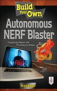
Drill four holes into the 10-inch gearbox arm—the arm that’s not an arm. Check out Figure 8-1 for reference. If you’re a perfectionist, there’s a drill template you can download from autonerfblaster.com, but four holes in a diamond or square pattern work nicely. You also can lay your blaster on the arm and use chalk or colored pencil to mark spots to drill. Two different drills were used for the arm on my system, but both held up well for either blaster once mounted.
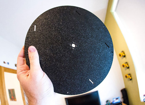
FIGURE 8-1 (a) Drilled holes in the 10-inch gearbox arm.
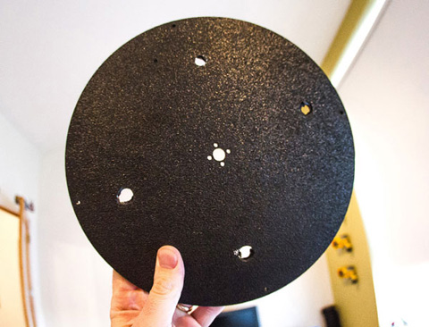
FIGURE 8-1 (b) Drilled holes in the 10-inch gearbox arm. Both hole marks work out well for either blaster.
HANDYMAN TIP Start with a small drill bit and work your way up to a ½-inch bit for easier drilling. You can easily drill the arm, but take it slow. There are no do-overs. Unless you buy another 10-inch arm.
Once you have the four holes drilled, get one of your Velcro straps. Thread the strap from the top of the arm, out the bottom, under the front of the blaster, and back up to the opposite hole. Using the power of Velcro, Velcro the strap to itself. In this case, pictures may explain better (see Figures 8-2 through 8-5).
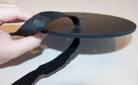

FIGURE 8-4 Pull the Velcro through the opposite side and even out the ending lengths like shoelaces.
• Use the second Velcro piece to strap the back of the blaster down. Now make sure that the blaster is nice and snug against the arm. It shouldn’t move about easily. Depending on your blaster, try out a crisscross pattern or a different strapping technique to get the blaster tight on the base. It should all feel like one cohesive piece.
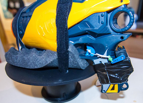
• Using a blaster with a rotund body? Consider putting some foam egg-crate mattress pad (Figure 8-6) as a buffer between the blaster and the arm. Even if your blaster isn’t rotund, the foam pad will help your blaster snuggle up tightly to the arm. You’ll need a 10” × 10” piece. Use scissors to trim off the excess pad to keep the unit from looking sloppy.

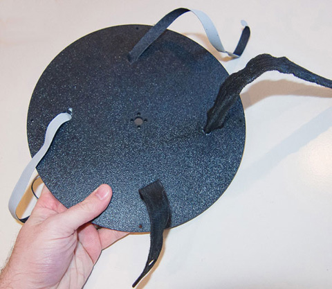
Now that you’ve done all that work to get the blaster nice and tight on the arm, admire how you did it. Then unstrap it. Hey, we’ve got to attach the arm to the base now. Use the 6-32 screws to attach the 10-inch gearbox arm—a.k.a. the disk, platter, saucer, Frisbee—to the base. Once attached, reenable the Velcro straps (don’t forget the foam pad, too). It should be looking like Figure 8-7 now. Now add the rubber feet to the bottom of the base. They will keep the base from slipping and sliding around on whatever surface you deploy your blaster on. If you ever lose the rubber feet, don’t fret. Just use a rubber jar opener as a replacement.
It’s Webcam Time
With the base and blaster united, it’s time to give it an eye. Depending on your webcam and your blaster, you may need to do a little creative duct taping when attaching the webcam to the top of the turret. Remember, we don’t want to weld anything or destroy the integrity of the blaster. We tinker in ways that we can untinker if necessary. Duct tape lets us quickly and easily explore different attachment options. Obviously, if you’re using a rogue blaster, you’ll have to discover the best way to strap the webcam to the blaster.
Something to consider. The webcam—especially the camera’s lens—must be centered, as shown on the Stampede in Figure 8-8. When the camera is placed directly above and centered over the barrel of the blaster, you’ll be assured of proper targeting when the blaster fires. OpenCV is analyzing the image for a face. If the webcam is pointed in a different direction than the blaster’s barrel, accuracy is diminished considerably, if not altogether.


Remember, this is tinkering. Once you’ve mastered a project, you can go back and figure out all the ways you can make it better in the 2.0 version. Then maybe you can write a book.
You should be looking at something like Figure 8-9 now.


Down to the Wiring
It’s time to plug everything together and give it the juice. You may want to consider cable management after this step; there is a slew of wires involved in our setup.
Make sure that the webcam and Arduino are plugged into your computer’s USB ports. If you don’t have two USB ports, you’ll need a powered USB hub. An unpowered USB hub won’t cut the mustard—no juice going to your webcam, Arduino board, and servos. #FAIL. For the servos, plug the signal cable into pins 9 and 10.
Now let’s discuss power. You have a few options, but there’s an issue we need to address. In our previous setups, we had plenty of pins for power. Now that we have two servos, we’re out of pins for 5-V power. That little 3.3-V power port may not do it. If you’re using the Hitec HS-311, you can use the 3.3-V port. However, if you have servos that thirst for 5-V power, let’s look at your options.
Option one is to use a battery for each servo and not worry about using the Arduino’s pins as the power source. For example, use a 9-V battery adapter and a male-to-male jumper wire to add stand-alone power to your servo. This method doesn’t share power with other components, so it’s purely for the servo—full juice.
No-pins option two is to hack a wire. Because you have exposed wires, make one into a pin by using the female end(s) of a jumper wire and splicing it to the positive/negative leads. Voilà! You now have an easy connection to the servo. You could apply this very same knowledge to the trigger servo you attached in Chapter 7 if you like. Just duct tape the battery to the blaster so that it’s not flapping around while the turret is looking for or tracking a target.
Everything all wired up—neat and pretty? Let’s get into the code.
Mouse Movement = Servo Movement
Blaster Coding for Processing
Let’s create a quick example project that will take your mouse’s current x coordinate and translate it to output the current angle to which the servo should rotate and then send it to the Arduino, where the data are parsed and the servo is rotated to the current angle. Here’s the code we’ll be using for this example:
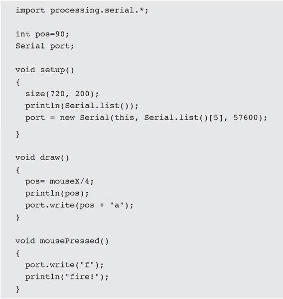
Let’s review what’s going down here. We’ll start by including the serial library that comes with Processing.
![]()
Next, we’ll set a serial variable so that we can specify which serial port to use and what settings it should have.
![]()
There’s also an integer, spos, that’s set to 90—as in 90 degrees, the angle with which the platform servo should begin. In setup(), we’ll list all the serial options available so that it’s easy to specify which one to use—similar to displaying the list of video sources we covered a few chapters back. Make sure that it’s the same one you use in the Arduino IDE to upload sketches.
![]()
This is what Processing returns on a Mac:

This is what Processing returns on a PC:
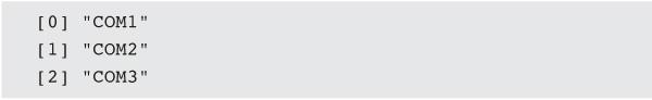
Based on the information returned from Processing, the current setup will be using the serial port labeled as
![]()
With this information, we can populate the port variable’s initialization settings. Make sure that you enter the proper value based on your available serial ports’ Processing displays. It most likely will not be 5!
![]()
Finally, in the draw() function, we’ll figure out the mouse’s current x coordinate and divide it by 4. There’s a reason the sketch’s dimensions are 720 pixels wide—it’s evenly divisible by 4. In this way, we’ll always stay between 0 and 180 when moving the mouse about the sketch. We’ll then send the current value to the console and then send the current mouse x coordinate to your Arduino.
It also should be noted that many out-of-the-box servos don’t move when between very low or very high degrees, such as 0 and 20 or 160 and 180 degrees. To get this granularity, you’ll need to invest in a servo programmer. For our needs, it doesn’t really make much difference until you’re really trying to eke out as much precision as possible.
When we’re ready to send a serial message to the Arduino, we’ll do it like this:
![]()
This command sends the angle, spos, along with an identifier, “a,” that will be deciphered by Arduino. In this case, “a” is telling Arduino the value at which to set the servo’s rotation angle.
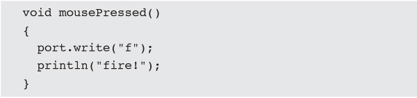
Finally, there’s mousePressed(), where the command is issued to activate the trigger servo (aka firing the blaster). In this case, only the letter “f” is sent. We also print the info to the console.
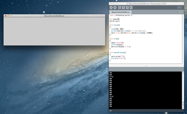
With this system, it’s quick and easy to send a directive to either fire or rotate. Go ahead and run the sketch to make sure that everything is working nicely in Processing (Figure 8-10). You’ll just see the console spitting out the angle the servo should be using or the command to fire. We’ll make it all harmonious when we complete the Arduino sketch—which is next!
Blaster Coding for Arduino
Now it’s time to get the Arduino board ready to receive data from Processing. Open the Arduino IDE, and upload this sketch. We’ll be using this sketch for the final blaster sketch as well, so once you upload this sketch, we’ll be done in the Arduino IDE for a bit. It should be noted that we won’t use the entire functionality of the sketch in this example, such as controlling the trigger servo, but we’ll cover what’s going on and use it fully in Chapter 9. Here’s the sketch in its entirety. Take a gander, and we’ll review what’s what.

This sketch acts as manager for commands received from Processing. To start, we’ve included Arduino’s built-in servo library and created two servo variables, servo1 and servo2—one for the base rotation and the other for trigger control, respectively. Next, we’ll create some variables for timing, which makes it easy to dictate how long the blaster should fire—assuming it’s an automatic blaster. How fast your trigger servo can rotate to pull the trigger and the time it takes to fire a few shots dictate how long the trigger should be held in the firing position—typically at a 180-degree rotation. You’ll need to fiddle with this amount to find the sweet spot in terms of duration and firing rate, but setting wait to 2,000 is a good starting point to get at least one dart to fire. The other variable, time, will keep track of when the command was sent—its value will be set when a fire command is received. Finally, isFiring keeps track of the firing status of the blaster, so continuous fire isn’t allowed. However, you may want to disable this feature to get continuous fire. Remember your dart capacity—you may run out of darts rather quickly. Using the method outlined earlier limits firing to short, controlled bursts.
Moving into setup(), we’ll specify which servo is attached to which pin—servo1, the base-rotation servo goes to pin 10, whereas servo2, the trigger servo, goes to pin 9. Lest we forget, serial communication for servos must occur at baud rate 57,600, so we’ll set that next. Rounding out setup(), we’ll set the starting angle, or neutral setting, of each servo—servo1 gets set to 90 degrees, whereas servo2 gets set to 0.
It also should be noted that while we’re working on the servos, especially the trigger servo, it’s a good idea to remove all darts from the blaster. You’ll want to test the functionality of all the components, but getting the trigger servo situated can definitely result in firing the blaster when you don’t necessarily want it to fire it. Be smart; remove darts during your initial tinker, and return them when you’re ready to test overall functionality!
Now to the meat of the program—the loop()! Here we’ll read serial data, assuming that they’re available, decode the value, and then determine what course of action to take. We start by declaring a static variable-v. A static variable is put into a special place in memory and kept there because its value will be used repeatedly, especially in our case here. Next, we’ll check to see whether any serial data are available to us by using an if() statement, which tests to see whether Serial.available() is greater than zero. If so, we’ll decipher what it is and do the appropriate action.
Here comes a programming doozy that may bake your noodle. In the if() statement, we’ll create a variable of type char—a data type that stores letters and symbols in Unicode format—and set it to the serial value by making it equal to Serial.read(). Then, using a switch statement, we’ll parse the data to do the appropriate action.
Did you just go cross-eyed? Let’s make this code easier to comprehend as serial data because char formats and char-format deciphering can get rather confusing. So once we’ve got the command from the serial connection and set it equal to the ch variable, it needs to be run through some quick processing, no pun intended, to break the information out. The switch() statement will use the value of ch, which is the serial data, and look for matches, which are called cases. Just think of it as a big if() statement in disguise. When a case is equal to the value of the serial data, its commands are executed, and the switch() ends with the break; command.
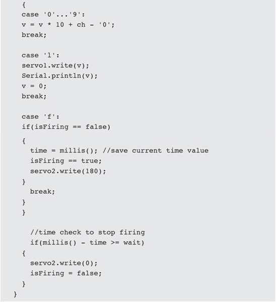
For example, Processing will send a value for the rotational servo, such as “45a,” over the serial connection. Arduino then will strip out the 45 and make it equal to the value of v. This is performed in the case ‘0’...’9’: of the switch() statement. The operation it performs is an ASCII lookup/conversion, which is somewhat advanced and difficult to explain as well. Just think of it this way—this case statement strips out the letter “a” from “45a” and sets v = 45. When the loop is entered again, ch will be equal to “a,” so case ‘a’ will be performed—moving the base-rotation servo to 45 degrees, printing the info to the serial monitor, and then resetting v. The process continues as serial data are read again and deciphered and commands are executed. All this happens so fast that the serial monitor output in the Arduino IDE scrolls by ridiculously quickly. It’s very efficient!
Should the command to fire be read, we’ll make sure that the blaster isn’t already firing. If not, we’ll set the variable time equal to millis(), which makes it equal to the current time. This is followed by setting isFiring to true and setting servo2 to 180 degrees—this means firing the blaster!
Next we’ll perform a check to make sure that we stop the blaster from firing after our predetermined waiting period has passed. Remember setting wait earlier? Here’s where we’ll use it:

If the current time, millis(), minus the timestamp set with time, is greater than wait, which was set at 2,000 (2 seconds), then it’s time to stop firing the blaster. This means releasing the servo with servo2.write(0) and setting isFiring to false.
Whew. That’s it! Upload the sketch to your Arduino board and start the serial monitor. Make sure that your servo pins are plugged in to match your Arduino sketch. Next, launch the Processing sketch and start moving your mouse back and forth. You should see the data being received in Arduino’s serial monitor. Oh, and the base? Yeah, that should totally be moving around based on your mouse’s movements. Click the mouse to send the fire command. If it works, load those darts back up and give it a quick spin.
When you’re done, go directly to Chapter 9 because we’ll tie face detection to the base rotation to follow targets and pepper them with some foam dart lovin’.
Now that the turret is following a target, it’s time to work on the threshold for firing. We’ll hone our Frankenblaster’s remote monitoring and sensing capabilities.