Chapter 5. Evolutionary Architecture Topologies
Discussions about architecture frequently boil down to coupling: how the pieces of the architecture connect and rely on one another. Many architects decry coupling as a necessary evil, but it’s difficult to build complex software without relying on (and coupling with) other components. Evolutionary architecture focuses on appropriate coupling—how to identify which dimensions of the architecture should be coupled to provide maximum benefit with minimal overhead and cost.
In this chapter, readers will garner a deeper understanding of architecture coupling, how that affects architectural structure, and how to evaluate the structure of software architectures to more effectively evolve them. We also provide some concrete terminology and advice on architecture topology from the component up through the system level.
Evolvable Architecture Structure
Different architecture styles have different evolution characteristics, but there is nothing inherent in the style that controls its ability to evolve. Rather, it boils down to the coupling characteristics supported by the architecture. It turns out that at least two different efforts from the past have identified the key enabler of evolution in software. Each of them provides a valuable perspective on coupling in architecture.
Connascence
In 1996, Meilir Page-Jones published What Every Programmer Should Know About Object-Oriented Design (Dorset House), which is a duplex book: one part covers an object-oriented design technique that did not prove to be popular. However, the lasting benefit from the book is a concept he named connascence. Here’s how he defined the term:
Two components are connascent if a change in one would require the other to be modified in order to maintain the overall correctness of the system.
Meilir Page-Jones
Essentially, connascence is an enhanced language to describe coupling. It’s a great language for architects to teach tech leads and developers, because it gives them a more concise way to discuss coupling and (more importantly) how to improve it. Having a richer vocabulary takes advantage of the Sapir–Whorf hypothesis.
Page-Jones developed two types of connascence: static and dynamic.
Static connascence
Static connascence refers to source code–level coupling (as opposed to execution-time coupling, covered in “Dynamic connascence”); it is a refinement of the afferent and efferent couplings defined by Structured Design. In other words, architects view the following types of static connascence as the degree to which something is coupled, either afferently or efferently:
- Connascence of Name (CoN)
-
Multiple components must agree on the name of an entity.
Names of methods represent the most common way that codebases are coupled and the most desirable, especially in light of modern refactoring tools that make system-wide name changes trivial.
- Connascence of Type (CoT)
-
Multiple components must agree on the type of an entity.
This type of connascence refers to the common facility in many statically typed languages to limit variables and parameters to specific types. However, this capability isn’t purely a language feature. Some dynamically typed languages offer selective typing, notably Clojure and Clojure Spec.
- Connascence of Meaning (CoM) or Connascence of Convention (CoC)
-
Multiple components must agree on the meaning of particular values.
The most common obvious case for this type of connascence in codebases is hardcoded numbers rather than constants. For example, it is common in some languages to consider defining
int TRUE = 1; int FALSE = 0. Imagine the problems if someone flips those values. - Connascence of Position (CoP)
-
Multiple components must agree on the order of values.
This is an issue with parameter values for method and function calls even in languages that feature static typing. For example, if a developer creates a method
void updateSeat(String name, String seatLocation)and calls it with the valuesupdateSeat("14D", "Ford, N"), the semantics aren’t correct even if the types are. - Connascence of Algorithm (CoA)
-
Multiple components must agree on a particular algorithm.
A common case for this type of connascence occurs when a developer defines a security hashing algorithm that must run on both the server and client and produce identical results to authenticate the user. Obviously, this represents a high form of coupling: if either algorithm changes any details, the handshake will no longer work.
Dynamic connascence
The other type of connascence Page-Jones defined is dynamic connascence, which analyzes calls at runtime. The following is a description of the different types of dynamic connascence:
- Connascence of Execution (CoE)
-
The order of execution of multiple components is important.
Consider this code:
email=newEmail();email.setRecipient("[email protected]");email.setSender("[email protected]");email.send();email.setSubject("whoops");It won’t work correctly because certain properties must be set in order.
- Connascence of Timing (CoT)
-
The timing of the execution of multiple components is important.
The common case for this type of connascence is a race condition caused by two threads executing at the same time, affecting the outcome of the joint operation.
- Connascence of Values (CoV)
-
This occurs when several values relate to one another and must change together.
Consider the case where a developer has defined a rectangle as four points, representing the corners. To maintain the integrity of the data structure, the developer cannot randomly change one of the points without considering the impact on the other points.
A more common and problematic case involves transactions, especially in distributed systems. When an architect designs a system with separate databases, yet needs to update a single value across all the databases, all the values must change together or not at all.
- Connascence of Identity (CoI)
-
This occurs when multiple components must reference the same entity.
The common example of this type of connascence involves two independent components that must share and update a common data structure, such as a distributed queue.
Architects have a harder time determining dynamic connascence because we lack tools to analyze runtime calls as effectively as we can analyze the call graph.
Connascence properties
Connascence is an analysis tool for architects and developers, and some properties of connascence help developers use it wisely. The following is a description of each of these connascence properties:
- Strength
-
Architects determine the strength of connascence by the ease with which a developer can refactor that type of coupling; different types of connascence are demonstrably more desirable, as shown in Figure 5-1. Architects and developers can improve the coupling characteristics of their codebase by refactoring toward better types of connascence.
Architects should prefer static connascence to dynamic connascence because developers can determine it through simple source code analysis, and modern tools make it trivial to improve static connascence. For example, consider the case of Connascence of Meaning, which developers can improve by refactoring to Connascence of Name by creating a named constant rather than a magic value.

Figure 5-1. The strength of connascence provides a good refactoring guide
- Locality
-
The locality of connascence measures the modules’ proximal location to one another in the codebase. Proximal code (in the same module) typically has more and higher forms of connascence than more separated code (in separate modules or codebases). In other words, forms of connascence that indicate poor coupling when far apart are fine when closer together. For example, if two classes in the same component have connascence of meaning, it is less damaging to the codebase than if two components have the same form of connascence.
Developers must consider strength and locality together. Stronger forms of connascence found within the same module represent less code smell than the same connascence spread apart.
- Degree
-
The degree of connascence relates to the size of its impact—does it impact a few classes or many? Lesser degrees of connascence damage codebases less. In other words, having high dynamic connascence isn’t terrible if you have only a few modules. However, codebases tend to grow, making a small problem correspondingly bigger.
Page-Jones offers three guidelines for using connascence to improve systems modularity:
-
Minimize overall connascence by breaking the system into encapsulated elements.
-
Minimize any remaining connascence that crosses encapsulation boundaries.
-
Maximize the connascence within encapsulation boundaries.
The legendary software architecture innovator Jim Weirich repopularized the concept of connascence and offers two great pieces of advice:
Rule of Degree: convert strong forms of connascence into weaker forms of connascence.
Rule of Locality: as the distance between software elements increases, use weaker forms of connascence.
Connascence Intersection with Bounded Context
Eric Evans’s book Domain-Driven Design has deeply influenced modern architectural thinking. Domain-driven design (DDD) is a modeling technique that allows for organized decomposition of complex problem domains. DDD defines the bounded context, where everything related to the domain is visible internally but opaque to other bounded contexts. The bounded context concept recognizes that each entity works best within a localized context. Thus, instead of creating a unified Customer class across the entire organization, each problem domain can create their own and reconcile differences at integration points. This isolation applies to other implementation details such as database schemas as well, leading to the degree of data isolation common in microservices, inspired by the concept of bounded context.
One goal of architects when designing systems based on DDD, including modular monoliths and microservices, is to prevent implementation details from “leaking” out of the bounded context. This doesn’t prevent the ability for bounded contexts to communicate, but that communication is mediated via a contract (see “Contracts” for more investigation of this topic).
Astute readers will notice commonality between the advice from 1993 about connascence locality and 2003’s advice about bounded context: allowing coupling to spread to broader scopes creates brittleness in architecture. A brittle architecture is one where a small change in one place may cause unpredicted and nonlocalized breakages elsewhere.
For example, consider the extreme case that unfortunately appears in some architectures: exposing an application’s database schema as an architecture integration point. The database schema for an application is part of what DDD calls the bounded context—an implementation detail. Exposing this detail to other applications means that a change in a single application’s database may unpredictably break other applications. Thus, exposing implementation details to a broader scope harms the overall integrity of the architecture.
The common trend in architecture that we’ve known since at least 1993 (and likely even before) is to restrict implementation coupling to the tightest scope possible—we’ve just struggled with the best ways to express it. Whether we call it bounded context or adhering to the locality principle of connascence, architects have struggled, dealt, and reconciled with coupling for decades.
While bounded context is the latest attempt to express an effective coupling philosophy, it originates from and has ties to DDD, and thus refers to the abstract design aspects of a system. We need an architectural concept that reflects bounded context, yet expresses it in technical architecture terms and allows tighter alignment with architectural concerns (rather than abstract design concerns).
Architectural Quanta and Granularity
Software systems are bound together in a variety of ways. As software architects, we analyze software using many different perspectives. But component-level coupling isn’t the only thing that binds software together. Many business concepts semantically bind parts of the system together, creating functional cohesion. To successfully evolve software, developers must consider all the coupling points that could break.
As defined in physics, the quantum is the minimum amount of any physical entity involved in an interaction. An architectural quantum is an independently deployable component with high functional cohesion, which includes all the structural elements required for the system to function properly. In a monolithic architecture, the quantum is the entire application; everything is highly coupled and therefore developers must deploy it en mass.
The term quantum is of course used heavily in the field of physics known as quantum mechanics. However, the authors chose the word for the same reasons physicists did. Quantum originated from the Latin word quantus, meaning “how great” or “how many.” Before physics co-opted it, the legal profession used it to represent the “required or allowed amount”—for example, in damages paid. And the term also appears in the mathematics field of topology, concerning the properties of families of shapes. Because of its Latin roots, the singular is quantum and the plural is quanta, similar to the datum/data symmetry.
An architecture quantum measures several different aspects of both topology and behavior in software architecture related to how parts connect and communicate with one another.
- Static coupling
-
Represents how static dependencies resolve within the architecture via contracts. These dependencies include operating system, frameworks and/or libraries delivered via transitive dependency management, and any other operational requirement to allow the quantum to operate.
- Dynamic coupling
-
Represents how quanta communicate at runtime, either synchronously or asynchronously. Thus, fitness functions for this characteristic must be continuous, typically utilizing monitors.
The static and dynamic coupling defined here match the concepts from connascence. An easy way to think about the difference is that static coupling describes how services are wired together, whereas dynamic coupling describes how services call one another at runtime. For example, in a microservices architecture, a service must contain dependent components such as a database, representing static coupling—the service isn’t operational without the necessary data. That service may call other services during the course of a workflow, which represents dynamic coupling. Neither service requires the other to be present to function, except for this runtime workflow. Thus, static coupling analyzes operational dependencies, and dynamic coupling analyzes communication dependencies.
- Architecture quantum
-
An architecture quantum is an independently deployable artifact with high functional cohesion, high static coupling, and synchronous dynamic coupling.
A common example of an architecture quantum is a well-formed microservice within a workflow.
These definitions include important characteristics; let’s cover each in detail as they inform most of the examples in the book.
Independently Deployable
Independently deployable implies several different aspects of an architecture quantum—each quantum represents a separate deployable unit within a particular architecture. Thus, a monolithic architecture—one that is deployed as a single unit—is by definition a single architecture quantum. Within a distributed architecture such as microservices, developers tend toward the ability to deploy services independently, often in a highly automated way. Thus, from an independently deployable standpoint, a service within a microservices architecture represents an architecture quantum (contingent on coupling—see below).
Making each architecture quantum represent a deployable asset within the architecture serves several useful purposes. First, the boundary represented by an architecture quantum serves as a useful common language among architects, developers, and operations—each understands the common scope under question: architects understand the coupling characteristics, developers understand the scope of behavior, and operations understands the deployable characteristics.
Second, it represents one of the forces (static coupling) architects must consider when striving for proper granularity of services within a distributed architecture. Often in microservices architectures, developers face the difficult question of what service granularity offers the optimum set of trade-offs. Some of those trade-offs revolve around deployability: what release cadence does this service require, what other services might be affected, what engineering practices are involved, and so on. Architects benefit from a firm understanding of exactly where deployment boundaries lie in distributed architectures.
Third, independent deployability forces the architecture quantum to include common coupling points such as databases. Most discussions about architecture conveniently ignore issues such as databases and user interfaces, but real-world systems must commonly deal with those problems. Thus, any system that uses a shared database fails the architecture quantum criterion for independent deployment unless the database deployment is in lockstep with the application. Many distributed systems that would otherwise qualify for multiple quanta fail the independently deployable part if they share a common database that has its own deployment cadence. Thus, merely considering the deployment boundaries doesn’t solely provide a useful measure. Architects should also consider the second criterion for an architecture quantum, high functional cohesion, to limit the architecture quantum to a useful scope.
High Functional Cohesion
High functional cohesion refers structurally to the proximity of related elements: classes, components, services, and so on. Throughout history, computer scientists defined a variety of types of cohesion, scoped in this case to the generic module, which may be represented as classes or components, depending on platform. From a domain standpoint, the technical definition of high functional cohesion overlaps with the goals of the bounded context in domain-driven design: behavior and data that implement a particular domain workflow.
From a purely independent deployability standpoint, a giant monolithic architecture qualifies as an architecture quantum. However, it almost certainly isn’t highly functionally cohesive but rather includes the functionality of the entire system. The larger the monolith, the less likely it is to be singularly functionally cohesive.
Ideally, in a microservices architecture, each service models a single domain or workflow and therefore exhibits high functional cohesion. Cohesion in this context isn’t about how services interact to perform work but how independent and coupled one service is to another service.
High Static Coupling
High static coupling implies that the elements inside the architecture quantum are tightly wired together, which is really an aspect of contracts. Architects recognize things like REST and SOAP as contract formats, but method signatures and operational dependencies (via coupling points such as IP addresses and URLs) also represent contracts, which we cover in “Contracts”.
An architecture quantum is in part a measure of static coupling, and the measure is quite simple for most architecture topologies. For example, the following diagrams show the architecture styles featured in the book Fundamentals of Software Architecture, with the architecture quantum static coupling illustrated.
Any of the monolithic architecture styles will necessarily have a quantum of one, as illustrated in Figure 5-2.

Figure 5-2. Monolithic architectures always have a quantum of one
As illustrated in Figure 5-2, any architecture that deploys as a single unit and utilizes a single database will always have a single quantum—the architecture quantum measure of static coupling includes the database, so a system that relies on a single database cannot have more than a single quantum. Thus, the static coupling measure of an architecture quantum helps identify coupling points in architecture, not just within the software components under development. Most domain architectures contain a single coupling point, typically a database, that makes their quantum measure one.
So far, the static coupling measurement of architecture quantum has evaluated all the topologies to one. However, distributed architectures create the possibility of multiple quanta but don’t necessarily guarantee it. For example, the mediator style of event-driven architecture will always be evaluated to a single architecture quantum, as illustrated in Figure 5-3.

Figure 5-3. A mediated event-driven architecture has a single architecture quantum
In Figure 5-3, even though the style represents a distributed architecture, two coupling points push this architecture toward a single architecture quantum: the database, as is common with monolithic architectures above, but also the Request Orchestrator itself—any holistic coupling point necessary for the architecture to function forms an architecture quantum around it.
Broker event-driven architectures (those without a central mediator) are less coupled, but that doesn’t guarantee complete decoupling. Consider the event-driven architecture illustrated in Figure 5-4.

Figure 5-4. Even a distributed architecture such as a broker-style event-driven architecture can be a single quantum
Figure 5-4 illustrates a broker-style event-driven architecture (without a central mediator) that is nevertheless a single architecture quantum because all the services utilize a single relational database, which acts as a common coupling point. The question answered by static analysis of an architecture quantum is whether it depends on the architecture necessary to bootstrap the service. Even in the case of an event-driven architecture where some of the services don’t access the database, if they rely on services that do access the database, then they become part of the static coupling of the architecture quantum.
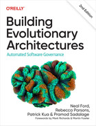
But what about situations in distributed architectures where common coupling points don’t exist? Consider the event-driven architecture illustrated in Figure 5-5. The architects designed an event-driven system with two data stores and no static dependencies between the sets of services. Note that either architecture quantum can run in a production-like ecosystem. It may not be able to participate in all workflows required by the system, but it runs successfully and operates—sending requests and receiving them within the architecture.
The static coupling measure of an architecture quantum assesses the coupling dependencies between architectural and operational components. Thus, the operating system, data store, message broker, container orchestration, and all other operational dependencies form the static coupling points of an architecture quantum, using the strictest possible contracts (more about the role of contracts in architecture quanta in “Contracts”).
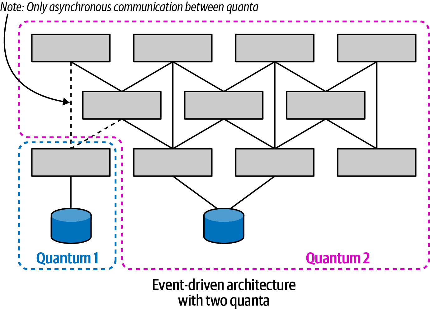
Figure 5-5. An event-driven architecture with two quanta
The microservices architecture style features highly decoupled services, including data dependencies. Architects in these architectures favor high degrees of decoupling and take care not to create coupling points between services, allowing the individual services to form their own quanta, as shown in Figure 5-6.

Figure 5-6. Microservices may form their own quanta
In Figure 5-6, each service (acting as a bounded context) may have its own set of architecture characteristics—one service might have higher levels of scalability or security than another. This granular level of architecture characteristics scoping represents one of the advantages of the microservices architecture style. High degrees of decoupling allow teams working on a service to move as quickly as possible, without worrying about breaking other dependencies.
However, if the system is tightly coupled to a user interface, the architecture forms a single architecture quantum, as illustrated in Figure 5-7.

Figure 5-7. A tightly coupled user interface can reduce a microservices architecture quantum to one
Traditionally, user interfaces create coupling points between the frontend and backend, and most user interfaces won’t operate if portions of the backend aren’t available.
Additionally, it will be difficult for an architect to design different levels of operational architecture characteristics (performance, scale, elasticity, reliability, etc.) for each service if they all must cooperate in a single user interface (particularly in the case of synchronous calls, covered in “Dynamic Quantum Coupling”).
Architects design user interfaces utilizing asynchronicity that doesn’t create coupling between front and back. A trend on many microservices projects is to use a micro-frontend framework for user interface elements in a microservices architecture. In such an architecture, the user interface elements that interact on behalf of the services are emitted from the services themselves. The user interface surface acts as a canvas where the user interface elements can appear and also facilitates loosely coupled communication between components, typically using events. Such an architecture is illustrated in Figure 5-8.

Figure 5-8. In a micro-frontend architecture, each service + user interface component forms an architecture quantum
In Figure 5-8, the four shaded services along with their corresponding micro-frontends form architecture quanta: each of these services may have different architecture characteristics.
Any coupling point in an architecture can create static coupling points from a quantum standpoint. Consider the impact of a database shared between two systems, as illustrated in Figure 5-9.
The static coupling of a system provides valuable insight, even in complex systems involving integration architecture. Increasingly, a common architecture technique for understanding legacy architecture involves creating a static quantum diagram of how things are “wired” together, which helps determine which systems will be impacted by change and offers a way of understanding (and potentially decoupling) the architecture.

Figure 5-9. A shared database forms a coupling point between two systems, creating a single quantum
Static coupling is only one of the forces at play in distributed architectures—the other is dynamic coupling.
Dynamic Quantum Coupling
The last portion of the architecture quantum definition concerns synchronous coupling at runtime—in other words, the behavior of architecture quanta as they interact with one another to form workflows within a distributed architecture.
The nature of how services call one another creates difficult trade-off decisions because it represents a multidimensional decision space, influenced by three interlocking forces:
- Communication
-
Refers to the type of connection synchronicity used: synchronous or asynchronous
- Consistency
-
Describes whether the workflow communication requires atomicity or can utilize eventual consistency
- Coordination
-
Describes whether the workflow utilizes an orchestrator or whether the services communicate via choreography
Communication
When two services communicate with each other, one of the fundamental questions for an architect is whether that communication should be synchronous or asynchronous.
Synchronous communication requires that the requestor wait for the response from the receiver, shown in Figure 5-10.

Figure 5-10. A synchronous call waits for a response from the receiver
In Figure 5-10, the calling service makes a call (using one of a number of protocols that support synchronous calls, such as gRPC) and blocks (does no further processing) until the receiver returns some value (or status indicating some state change or error condition).
Asynchronous communication occurs between two services when the caller posts a message to the receiver (usually via some mechanism such as a message queue), and once the caller gets acknowledgment that the message will be processed, it returns to work. If the request requires a response value, the receiver can use a reply queue to (asynchronously) notify the caller of the result, which is illustrated in Figure 5-11.

Figure 5-11. Asynchronous communication allows parallel processing
In Figure 5-11, the caller posts a message to a message queue and continues processing until notified by the receiver that the requested information is available via return call. Generally, architects use message queues (illustrated by the metaphorical pipes which overlay the communication arrows) to implement asynchronous communication, but queues are common and create noise on diagrams, so many architects leave them off, as shown in the lower diagram. And, of course, architects can implement asynchronous communication without message queues using a variety of libraries or frameworks. Both diagrams in Figure 5-11 imply asynchronous messaging, but the bottom one provides visual shorthand and less implementation detail.
Architects must consider a number of significant trade-offs when choosing how services will communicate. Decisions around communication affect synchronization, error handling, transactionality, scalability, and performance. The remainder of this book delves into many of these issues.
Consistency
Consistency refers to the strictness of transactional integrity that communication calls must adhere to. Atomic transactions (all-or-nothing transactions requiring consistency during the processing of a request) lie on one side of the spectrum, and different degrees of eventual consistency lie on the other side.
Transactionality—having several different services participate in an all-or-nothing transaction—is one of the most difficult problems to model in distributed architectures, resulting in the general advice to try to avoid cross-service transactions. This complex subject is covered in the book Software Architecture: The Hard Parts (O’Reilly) and is beyond the scope of this book.
Coordination
Coordination refers to how much coordination the workflow modeled by the communication requires. The two common generic patterns for microservices are orchestration and choreography. Simple workflows—a single service replying to a request—don’t require special consideration from this dimension. However, as workflow complexity grows, so too does the need for coordination.
These three factors—communication, consistency, and coordination—all inform the important decisions an architect must make. Critically, however, architects cannot make these choices in isolation—each option has a gravitational effect on the others. For example, transactionality is easier in synchronous architectures with orchestration, whereas higher levels of scale are possible with eventually consistent-asynchronous-choreographed systems.
Thinking about these forces as being related to each other forms a three-dimensional space, illustrated in Figure 5-12.
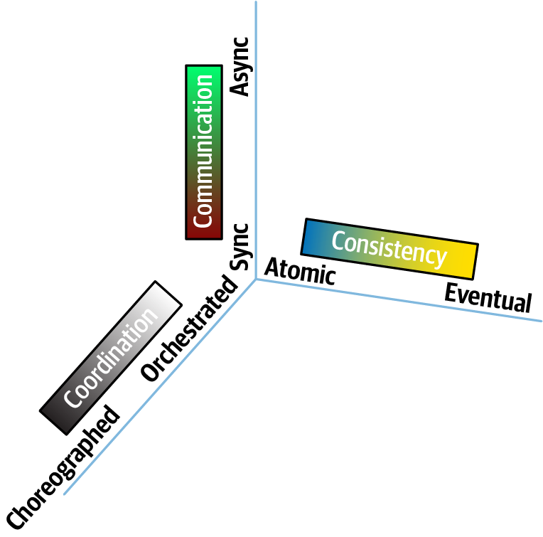
Figure 5-12. The dimensions of dynamic quantum coupling
In Figure 5-12, each force in play during service communication appears as a dimension. For a particular decision, an architect could graph the position in space representing the strength of these forces. From a practical standpoint, architects must create matrices to investigate the impact of changing any one of these conjoined forces.
Contracts
One constant factor in software architecture that cuts across and affects virtually every aspect of architect decision-making is contracts, broadly defined as how disparate parts of an architecture connect with one another. The dictionary definition of a contract is:
- Contract
-
A written or spoken agreement, especially one concerning employment, sales, or tenancy, that is intended to be enforceable by law.
In software, we use contracts broadly to describe things like integration points in architecture, and many contract formats are part of the design process of software development: SOAP, REST, gRPC, XML-RPC, and an alphabet soup of other acronyms. However, we broaden that definition and make it more consistent:
This definition of contract encompasses all techniques used to “wire together” parts of a system, including transitive dependencies for frameworks and libraries, internal and external integration points, caches, and any other communication between parts.
Contracts in software architecture range from strict to loose, as illustrated in Figure 5-13.

Figure 5-13. The spectrum of contract types from strict to loose
In Figure 5-13, where several exemplar contract types appear for illustration, a strict contract requires adherence to names, types, ordering, and all other details, leaving no ambiguity. An example of the strictest possible contract in software is a remote method call, using a platform mechanism such as RMI in Java. In that case, the remote call mimics an internal method call, matching name, parameters, types, and all other details.
Many strict contract formats mimic the semantics of method calls. For example, developers see a host of protocols that include some variation of the “RPC,” traditionally an acronym for Remote Procedure Call. gRPC is an example of a popular remote invocation framework that defaults to strict contracts.
Many architects like strict contracts because they model the semantic behavior of internal method calls. However, strict contracts create brittleness in integration architecture, something to avoid. As discussed in “Reuse Patterns”, something that is simultaneously frequently changing and used by several distinct architecture parts creates problems in architecture; contracts fit that description because they form the glue within a distributed architecture: the more frequently they must change, the more rippling problems they cause for other services. However, architects aren’t forced to use strict contracts, and they should do so only when advantageous.
Even an ostensibly loose format such as JSON offers ways to selectively add schema information to simple name/value pairs. Example 5-1 shows a strict JSON contract with schema information attached.
Example 5-1. Strict JSON contract
{"$schema":"http://json-schema.org/draft-04/schema#","properties":{"acct":{"type":"number"},"cusip":{"type":"string"},"shares":{"type":“number", "minimum": 100}},"required": ["acct", "cusip", "shares"]}
In Example 5-1, the first line references the schema definition we use and will validate against. We define three properties: acct, cusip, and shares, along with their types and, on the last line, which ones are required. This creates a strict contract, with required fields and types specified.
Examples of looser contracts include formats such as REST and GraphQL, which are very different formats but demonstrate looser coupling than RPC-based formats. For REST, the architect models resources rather than method or procedure endpoints, making for less brittle contracts. For example, if an architect builds a RESTful resource that describes parts of an airplane to support queries about seats, that query won’t break in the future if someone adds details about engines to the resource—adding more information doesn’t break what’s there.
Similarly, GraphQL is used by distributed architectures to provide read-only aggregated data rather than perform costly orchestration calls across a wide variety of services. Consider the two examples of GraphQL representations appearing in Examples 5-2 and 5-3, providing two different but capable views of the Profile contract.
Example 5-2. Customer Wishlist Profile representation
typeProfile{name:String}
Example 5-3. Customer Profile representation
typeProfile{name:Stringaddr1:Stringaddr2:Stringcountry:String...}
The concept of profile appears in both Examples 5-2 and 5-3 but with different values. In this scenario, the Customer Wishlist doesn’t have internal access to the customer’s name, only a unique identifier. Thus, it needs access to a Customer Profile that maps the identifier to the customer name. The Customer Profile includes a large amount of information about the customer in addition to the name. As far as Wishlist is concerned, the only interesting thing in Profile is the name.
A common antipattern that some architects fall victim to is to assume that Wishlist might eventually need all the other parts, so they include them in the contract from the outset. This is an example of Stamp Coupling and is an antipattern in most cases because it introduces breaking changes where they aren’t needed, making the architecture fragile yet receiving little benefit. For example, if Wishlist cares only about the customer name from Profile, but the contract specifies every field in Profile (just in case), then a change in Profile that Wishlist doesn’t care about causes a contract breakage and coordination to fix.
Keeping contracts at a “need to know” level strikes a balance between semantic coupling and necessary information without creating needless fragility in integration architecture.
At the far end of the spectrum of contract coupling lie extremely loose contracts, often expressed as name/value pairs in formats like YAML and JSON, illustrated in Example 5-4.
Example 5-4. Name/value pairs in JSON
{"name":"Mark","status":"active","joined":"2003"}
Nothing but the raw facts in Example 5-4! No additional metadata, type information, or anything else, just name/value pairs.
Using such loose contracts allows for extremely decoupled systems, often one of the goals in architectures such as microservices. However, the looseness of the contract comes with trade-offs, including lack of contract certainty, verification, and increased application logic. The formerly contractual concerns are often replaced with fitness functions.
Case Study: Microservices as an Evolutionary Architecture
A microservices architecture defines physical bounded contexts between architectural elements, encapsulating all the parts that might change. This type of architecture is designed to allow incremental change. In a microservices architecture, the bounded context serves as the quantum boundary and includes dependent components such as database servers. It may also include architecture components such as search engines and reporting tools—anything that contributes to the delivered functionality of the service, as shown in Figure 5-14.
Figure 5-14. The architectural quantum in microservices encompasses the service and all its dependent parts
In Figure 5-14, the service includes code components, a database server, and a search engine component. Part of the bounded context philosophy of microservices operationalizes all the pieces of a service together, leaning heavily on modern DevOps practices. In the following section, we investigate some common architectural patterns and their typical quantum boundaries.
Traditionally isolated roles such as architect and operations must coordinate in an evolutionary architecture. Architecture is abstract until operationalized; developers must pay attention to how their components fit together in the real world. Regardless of which architecture pattern developers choose, architects should also explicitly define their quantum size. Small quanta imply faster change because of small scope. Generally, small parts are easier to work with than big ones. Quantum size determines the lower bound of the incremental change possible within an architecture.
Combining the engineering practices of Continuous Delivery with the physical partitioning of bounded context forms the philosophical basis for the microservice style of architecture, along with our architectural quantum concept.
In a layered architecture, the focus is on the technical dimension, or how the mechanics of the application work: persistence, UI, business rules, and so forth. Most software architectures focus primarily on these technical dimensions. However, an additional perspective exists. Suppose that one of the key bounded contexts in an application is Checkout. Where does it live in the layered architecture? Domain concepts like Checkout smear across the layers in this architecture. Because the architecture is segregated via technical layers, there is no clear concept of the domain dimension in this architecture, as can be seen in Figure 5-15.

Figure 5-15. The domain dimension is embedded within technical architecture
In Figure 5-15, some portion of Checkout exists in the UI, another portion lives in the business rules, and persistence is handled by the bottom layers. Because layered architecture isn’t designed to accommodate domain concepts, developers must modify each layer to make changes to domains. From a domain perspective, a layered architecture has zero evolvability. In highly coupled architectures, change is difficult because coupling between the parts developers want to change is high. Yet, in most projects, the common unit of change revolves around domain concepts. If a software development team is organized into silos resembling their role in the layered architecture, then changes to Checkout require coordination across many teams.
In contrast, consider an architecture where the domain dimension is the primary segregation of the architecture, as shown in Figure 5-16.
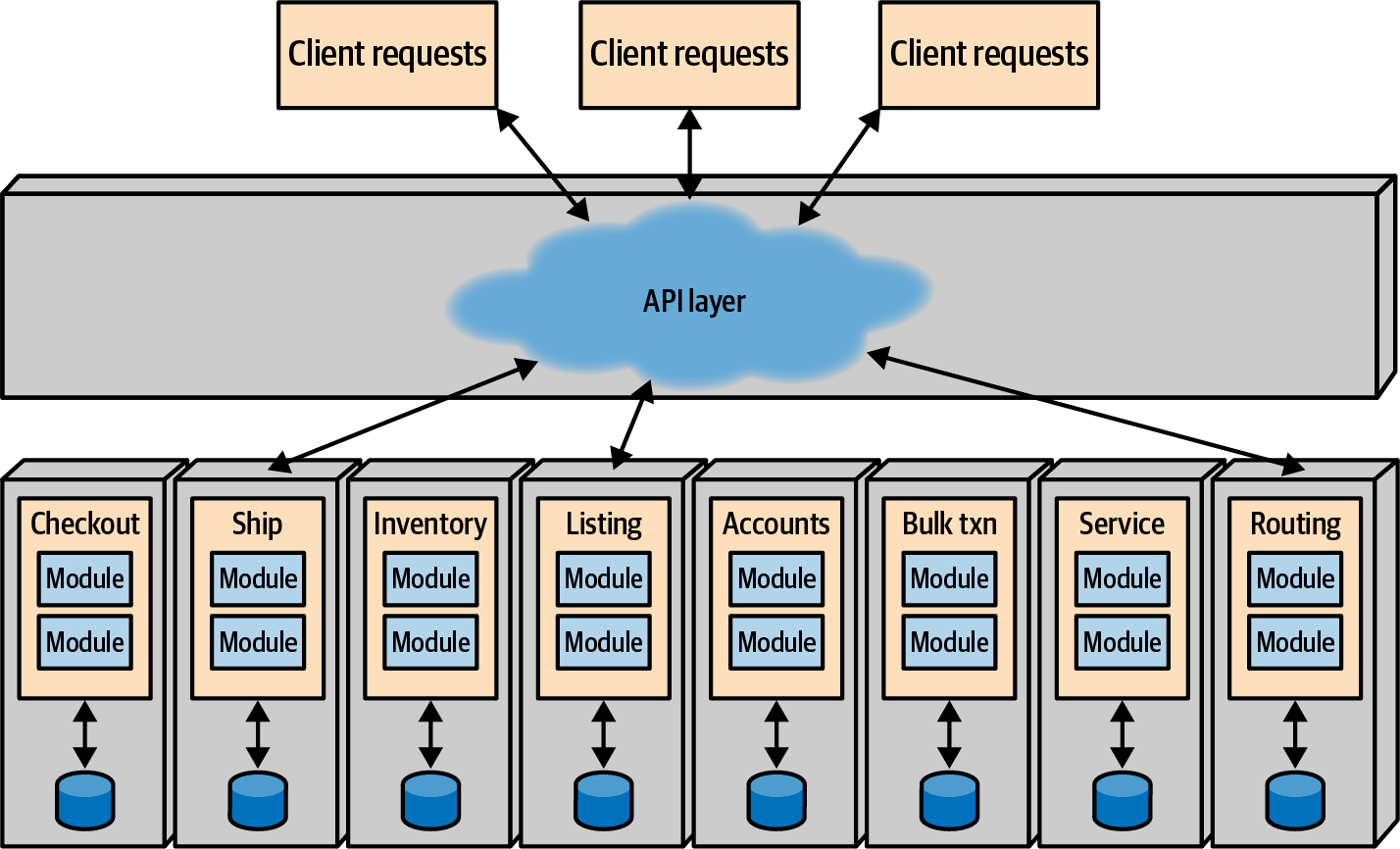
Figure 5-16. Microservices architectures partition across domain lines, embedding the technical architecture
As shown in Figure 5-16, each service is defined around the DDD concept, encapsulating the technical architecture and all other dependent components (like databases) into a bounded context and creating a highly decoupled architecture. Each service “owns” all parts of its bounded context and communicates with other bounded contexts via messaging (such as REST or message queues). Thus, no service is allowed to know the implementation details of another service (such as database schemas), preventing inappropriate coupling. The operational goal of this architecture is to replace one service with another without disrupting other services.
Microservices architectures generally follow seven principles, as discussed in Building Microservices Architectures:
- Modeled around the business domain
-
The emphasis in microservices design is on the business domain, not technical architecture. Thus, the quantum reflects the bounded context. Some developers make the mistaken association that a bounded context represents a single entity such as
Customer; instead, it represents a business context and/or workflow such asCatalogCheckout. The goal in microservices isn’t to see how small developers can make each services but rather to create a useful bounded context. - Hide implementation details
-
The technical architecture in microservices is encapsulated within the service boundary, which is based on the business domain. Each domain forms a physical bounded context. Services integrate with each other by passing messages or resources, not by exposing details like database schemas.
- Culture of automation
-
Microservices architectures embrace Continuous Delivery, by using deployment pipelines to rigorously test code and automate tasks like machine provisioning and deployment. Automated testing in particular is extremely useful in fast-changing environments.
- Highly decentralized
-
Microservices form a shared nothing architecture—the goal is to decrease coupling as much as possible. Generally, duplication is preferable to coupling. For example, both the
CatalogCheckoutandShipToCustomerservices have a concept calledItem. Because both teams have the same name and similar properties, developers try to reuse it across both services, thinking it will save time and effort. Instead, it increases effort because changes must now propagate between all the teams that share the component. And whenever a service changes, developers must worry about changes to the shared component. If, on the other hand, each service has its ownItemand passes information it needs fromCatalogCheckouttoShipToCustomerwithout coupling to the component, it can change independently. - Deployed independently
-
Developers and operations expect that each service component will be deployed independently from other services (and other infrastructure), reflecting the physical manifestation of the bounded context. The ability for developers to deploy one service without affecting any other service is one of the defining benefits of this architectural style. Moreover, developers typically automate all deployment and operations tasks, including parallel testing and Continuous Delivery.
- Isolate failure
-
Developers isolate failure both within the context of a microservice and in the coordination of services. Each service is expected to handle reasonable error scenarios and recover if possible. Many DevOps best practices (such as the Circuit Breaker pattern, bulkheads, etc.) commonly appear in these architectures. Many microservices architectures adhere to the Reactive Manifesto, a list of operational and coordination principles that lead to more robust systems.
- Highly observable
-
Developers cannot hope to manually monitor hundreds or thousands of services (how many multicast SSH terminal sessions can one developer observe?). Thus, monitoring and logging become first-class concerns in this architecture. If operations cannot monitor one of these services, it might as well not exist.
The main goals of microservices are isolation of domains via physical bounded context and emphasis on understanding the problem domain. Therefore, the architectural quantum is the service, making this an excellent example of an evolutionary architecture. If one service needs to evolve to change its database, no other service is affected because no other service is allowed to know implementation details like schemas. Of course, the developers of the changing service will have to deliver the same information via the integration point between the services (hopefully protected by a fitness function like consumer-driven contracts), allowing the calling service developers the bliss of never knowing the change occurred.
Given that microservices is our exemplar for an evolutionary architecture, it is unsurprising that it scores well from an evolutionary standpoint.
- Incremental change
-
Both aspects of incremental change are easy in microservices architectures. Each service forms a bounded context around a domain concept, making it easy to make changes that only affect that context. Microservices architectures rely heavily on automation practices from Continuous Delivery, utilizing deployment pipelines and modern DevOps practices.
- Guided change with fitness functions
-
Developers can easily build both atomic and holistic fitness functions for microservices architectures. Each service has a well-defined boundary, allowing a variety of levels of testing within the service components. Services must coordinate via integration, which also requires testing. Fortunately, sophisticated testing techniques grew alongside the development of microservices.
If there are clear benefits, then why haven’t developers embraced this style before? Years ago, automatic provisioning of machines wasn’t possible. While we had virtual machine (VM) technology, they were often handcrafted with long lead times. Operating systems were commercial and licensed, with little support for automation. Real-world constraints like budgets impact architectures, which is one of the reasons developers build more and more elaborate shared resources architectures, segregated at the technical layers. If operations is expensive and cumbersome, architects build around it, as they did in enterprise service bus-driven service-oriented architectures.
The Continuous Delivery and DevOps movements added a new factor into the dynamic equilibrium. Now, machine definitions live in version control and support extreme automation. Deployment pipelines spin up multiple test environments in parallel to support safe continuous deployment. Because much of the software stack is open source, licensing and other concerns have less impact on architectures. The community reacted to the new capabilities emergent in the software development ecosystem to build more domain-centric architectural styles.
In microservices architecture, the domain encapsulates technical and other architectures, making evolution across domain dimensions easy. No one perspective on architecture is “correct” but rather a reflection of the goals developers build into their projects. If the focus is entirely on technical architecture, then making changes across that dimension is easier. However, if the domain perspective is ignored, then evolving across that dimension is no better than the Big Ball of Mud.
Reuse Patterns
As an industry, we have benefited greatly from reusable frameworks and libraries built by others, often open source and freely available. Clearly, the ability to reuse code is good. However, like all good ideas, many companies abuse this idea and create problems for themselves. Every corporation desires code reuse because software seems so modular, like electronics components. However, despite the promise that exists for truly modular software, it has consistently evaded us.
Software reuse is more like an organ transplant than snapping together Lego blocks.
John D. Cook
While language designers have promised developers Lego blocks for a long time, we still seem to have organs. Software reuse is difficult and doesn’t come automatically. Many optimistic managers assume any code that developers write is inherently reusable, but this is not always the case. Many companies have attempted and succeeded in writing truly reusable code, but it is intentional and difficult. Developers often spend a lot of time trying to build reusable modules that turn out to have little practical reuse.
In service-oriented architectures (SOAs), the common practice was to find commonalities and reuse as much as possible. For example, imagine that a company has two contexts: Checkout and Shipping. In an SOA, architects observe that both contexts include the concept of Customer. This, in turn, encourages them to consolidate both customers into a single Customer service, coupling both Checkout and Shipping to the shared service. Architects worked toward a goal of ultimate canonicality in SOA—every concept has a single (shared) home.
Ironically, the more effort developers put into making code reusable, the harder it is to use. Making code reusable involves adding options and decision points to accommodate the different uses. The more developers add hooks to enable reusability, the more they harm the basic usability of the code.
Note
The more reusable code is, the less usable it is.
In other words, ease of code use is often inversely proportional to how reusable that code is. When developers build code to be reusable, they must add features to accommodate the myriad ways they and other developers will eventually use the code. All that future-proofing makes it more difficult for developers to use the code for a single purpose.
Microservices eschew code reuse, adopting the philosophy of prefer duplication to coupling: reuse implies coupling, and microservices architectures are extremely decoupled. However, the goal in microservices isn’t to embrace duplication but rather to isolate entities within domains. Services that share a common class are no longer independent. In a microservices architecture, Checkout and Shipping would each have their own internal representation of Customer. If they need to collaborate on customer-related information, they send the pertinent information to each other. Architects don’t try to reconcile and consolidate the disparate versions of Customer in their architecture. The benefits of reuse are illusory and the coupling it introduces comes with its disadvantages. Thus, while architects understand the downsides of duplication, they offset that localized damage to the architectural damage too much coupling introduces.
Code reuse can be an asset but also a potential liability. Make sure the coupling points introduced in your code don’t conflict with other goals in the architecture. For example, microservices architectures typically use a service mesh to couple the parts of services together that help unify a particular architectural concern, such as monitoring or logging.
Effective Reuse = Abstraction + Low Volatility
A common problem faced by many architects today lies with reconciling two differing corporate objectives: holistic reuse versus isolation via bounded contexts, inspired by DDD. Large organizations understandably want to utilize as much reuse across their ecosystem as possible—the more they can reuse, the less they have to write from scratch. However, reuse creates coupling, which many architects try to avoid, especially coupling that extends too far.
Sidecars and Service Mesh: Orthogonal Operational Coupling
One of the design goals of microservices architectures is a high degree of decoupling, often manifested in the advice “Duplication is preferable to coupling.” For example, let’s say that two PenultimateWidgets services need to pass customer information, yet domain-driven design’s bounded context insists that implementation details remain private to the service. A common solution allows each service its own internal representation of entities such as Customer, passing that information in loosely coupled ways such as name/value pairs in JSON. Notice that this allows each service to change its internal representation at will, including the technology stack, without breaking the integration. Architects generally frown on duplicating code because it causes synchronization issues, semantic drift, and a host of other issues, but sometimes forces exist that are worse than the problems of duplication, and coupling in microservices often fits that bill. Thus, in microservices architecture, the answer to the question of “should we duplicate or couple to some capability” is likely duplicate, whereas in another architecture style such as a service-based architecture, the correct answer is likely couple. It depends!
When designing microservices, architects have resigned themselves to the reality of implementation duplication to preserve decoupling. But what about the types of capabilities that benefit from high coupling, such as monitoring, logging, authentication and authorization, circuit breakers, and a host of other operational abilities that each service should have? Allowing each team to manage these dependencies often descends into chaos. For example, consider a company like PenultimateWidgets trying to standardize on a common monitoring solution, to make it easier to operationalize its various services. If each team is responsible for implementing monitoring for their service, how can the operations team be sure they did? Also, what about issues such as unified upgrades? If the monitoring tool needs to upgrade across the organization, how can teams coordinate that?
The common solution that has emerged in the microservices ecosystem over the past few years solves this problem in an elegant way using the Sidecar pattern, based on a much earlier architecture pattern defined by Alistair Cockburn known as the Hexagonal architecture, illustrated in Figure 5-17.

Figure 5-17. The Hexagonal Pattern separated domain logic from technical coupling
In Figure 5-17, what we would now call the domain logic resides in the center of the hexagon, which is surrounded by ports and adapters to other parts of the ecosystem (in fact, this pattern is alternately known as the Ports and Adapters pattern). While predating microservices by a number of years, this pattern has similarities to modern microservices, with one significant difference: data fidelity. The hexagonal architecture treated the database as just another adapter that can be plugged in, but one of the insights from DDD suggests that data schemas and transactionality should be inside the interior—like microservices.
The Sidecar pattern leverages the same concept as hexagonal architecture in that it decouples the domain logic from the technical (infrastructure) logic. For example, consider the two microservices shown in Figure 5-18.

Figure 5-18. Two microservices that share the same operational capabilities
In Figure 5-18, each service includes a split between operational concerns (the larger components toward the bottom of the service) and domain concerns (pictured in the boxes toward the top of the service labeled “Domain”). If architects desire consistency in operational capabilities, the separable parts go into a sidecar component, metaphorically named for the sidecar that attaches to motorcycles, whose implementation is either a shared responsibility across teams or managed by a centralized infrastructure group. If architects can assume that every service includes the sidecar, it forms a consistent operational interface across services, typically attached via a service plane, shown in Figure 5-19.

Figure 5-19. When each microservice includes a common component, architects can establish links between them for consistent control
If architects and operations can safely assume that every service includes the sidecar component (governed by fitness functions), it forms a service mesh, illustrated in Figure 5-20, where the boxes to the right of each service all interconnect, forming a “mesh.”
Having a mesh allows architects and DevOps to create dashboards, control operational characteristics such as scale, and implement a host of other capabilities.
The Sidecar pattern allows governance groups like enterprise architects a reasonable restraint over too many polyglot environments: one of the advantages of microservices is a reliance on integration rather than a common platform, allowing teams to choose the correct level of complexity and capabilities on a service-by-service basis. However, as the number of platforms proliferates, unified governance becomes more difficult. Therefore, teams often use the consistency of the service mesh as a driver to support infrastructure and other cross-cutting concerns across multiple heterogeneous platforms. For example, without a service mesh, if enterprise architects want to unify around a common monitoring solution, then teams must build one sidecar per platform that supports that solution.

Figure 5-20. A service mesh is a set of operational links between services
The Sidecar pattern represents not only a way to decouple operational capabilities from domains, it’s also an orthogonal reuse pattern to address orthogonal coupling (see “Orthogonal Coupling”). Often, architectural solutions require several different types of coupling, such as our current example of domain versus operational coupling. An orthogonal reuse pattern presents a way to reuse some aspect counter to one or more seams in the architecture. For example, microservices architectures are organized around domains, but operational coupling requires cutting across those domains. A sidecar allows an architect to isolate those concerns in a cross-cutting but consistent layer through the architecture.
The Sidecar pattern and service mesh offer a clean way to spread some sort of cross-cutting concern across a distributed architecture, and can be used by more than just operational coupling (see the next section). It offers an architectural equivalent to the Decorator pattern from the Gang of Four’s book Design Patterns: it allows an architect to “decorate” behavior across a distributed architecture independent of the normal connectivity.
Data Mesh: Orthogonal Data Coupling
Observing the other trends in distributed architectures, Zhamak Dehghani and several other innovators derived the core idea from domain-oriented decoupling of microservices, the service mesh, and the Sidecar pattern and applied it to analytical data, with modifications. As we mentioned in the previous section, the Sidecar pattern provides a nonentangling way to organize orthogonal coupling; the separation between operational and analytical data is another excellent example of just such a coupling, but with more complexity than simple operational coupling.
Definition of Data Mesh
Data Mesh is an approach to sharing, accessing, and managing analytical data in a decentralized fashion. It satisfies a wide range of analytical use cases, such as reporting, training ML models, and generating insights. Contrary to the previous architecture, it does so by aligning the architecture and ownership of the data with the business domains and enabling a peer-to-peer consumption of data.
Data Mesh is founded on the following principles:
- Domain ownership of data
-
Data is owned and shared by the domains that are most intimately familiar with the data: those that either are originating the data or are the first-class consumers of the data. The architecture allows for the distributed sharing and access of the data from multiple domains and in a peer-to-peer fashion without the intermediate transformation steps required in data warehouses or the centralized storage of the Data Lake.
- Data as a product
-
To prevent siloing of data and to encourage domains to share their data, Data Mesh introduces the concept of data served as a product. It puts in place the organizational roles and success metrics necessary to ensure that domains provide their data in a way that provides a positive experience to data consumers across the organization. This principle leads to the introduction of a new architectural quantum, called a data product quantum, to maintain and serve discoverable, understandable, timely, secure, and high-quality data to consumers. This chapter introduces the architectural aspect of the data product quantum.
- Self-serve data platform
-
In order to empower the domain teams to build and maintain their data products, Data Mesh introduces a new set of self-serve platform capabilities. The capabilities focus on improving the experience of data product developers and consumers. It includes features such as declarative creation of data products, discoverability of data products across the mesh through search and browsing, and management of the emergence of other intelligent graphs such as lineage of data and knowledge graphs.
- Computational federated governance
-
This principle ensures that despite decentralized ownership of the data, organization-wide governance requirements such as compliance, security, privacy, quality of data, and interoperability of data products are met consistently across all domains. Data Mesh introduces a federated decision-making model composed of domain data product owners. The policies they formulate are automated and embedded as code in each and every data product. The architectural implication of this approach to governance is a platform-supplied embedded sidecar in each data product quantum to store and execute the policies at the point of access: data read or write.
Data Mesh is a wide-ranging topic, fully covered in the book Data Mesh: Delivering Data-Driven Value at Scale (O’Reilly). In this chapter, we focus on the core architectural element, the data product quantum.
Data product quantum
The core tenet of the Data Mesh lies atop modern distributed architectures such as microservices. Just as in the service mesh, teams build a data product quantum (DPQ) adjacent but coupled to their service, as illustrated in Figure 5-21.
The service Alpha contains both behavioral and transactional (operational) data. The domain also includes a data product quantum, which also contains code and data, which acts as an interface to the overall analytical and reporting portion of the system. The DPQ acts as an operationally independent but highly coupled set of behaviors and data.

Figure 5-21. Structure of a data product quantum
Several types of DPQs commonly exist in modern architectures:
- Source-aligned (native) DPQ
-
Provides analytical data on behalf of the collaborating architecture quantum, typically a microservice, acting as a cooperative quantum.
- Aggregate DQP
-
Aggregates data from multiple inputs, either synchronously or asynchronously. For example, for some aggregations, an asynchronous request may be sufficient; for others, the aggregator DPQ may need to perform synchronous queries for a source-aligned DPQ.
- Fit-for-purpose DPQ
-
Custom-made DPQ to serve a particular requirement, which may encompass analytical reporting, business intelligence, machine learning, or some other supporting capability.
A particular domain may include multiple DPQs, depending on differing architecture characteristics for different types of analysis. For example, one DPQ may need different levels of performance than another.
Each domain that also contributes to analysis and business intelligence includes a DPQ, as illustrated in Figure 5-22.

Figure 5-22. The data product quantum acts as a separate but highly coupled adjunct to a service
In Figure 5-22, the DPQ represents a component owned by the domain team responsible for implementing the service. It overlaps information stored in the database, and may have interactions with some of the domain behavior asynchronously. The data product quantum also likely has behavior as well as data for the purposes of analytics and business intelligence.
Each data product quantum acts as a cooperative quantum for the service itself:
- Cooperative quantum
-
An operationally separate quantum that communicates with its cooperator via asynchronous communication and eventual consistency yet features tight contract coupling with its cooperator and generally looser contract coupling to the analytics quantum, the service responsible for reports, analysis, business intelligence, and so on.
While the two cooperating quanta are operationally independent, they represent two sides of data: operational data in the service and analytical data in the data product quantum.
Some portion of the system will carry the responsibility for analytics and business intelligence, which will form its own domain and quantum. To operate, this analytical quantum has static quantum coupling to the individual data product quanta it needs for information. This service may make either synchronous or asynchronous calls to the DPQ, depending on the type of request. For example, some DPQs will feature a SQL interface to the analytical DPQ, allowing synchronous queries. Other requirements may aggregate information across a number of DPQs.
Data Mesh is an excellent example of the innovative mashup between microservices architectures and analytical data, and it is a road map for managing orthogonal coupling in distributed architectures. The concept of the sidecar and cooperative quantum allows architects to selectively “overlay” one architecture atop another. This allows preferred modeling of domains (such as DDD) while allowing separate concerns well-governed access to what they need.
Summary
Understanding the impact of structure on the ability to evolve a software system is key for architects. While a number of named architectural styles exist, the primary characteristic of those architectures that determines evolvability is controlled coupling. Whether inspired by the locality property of connascence or bounded context in DDD, controlling the extent of implementation coupling is the key to building evolvable architectures.
Contracts allow different architecture parts to communication without creating tight coupling points. Using loosely defined coupling points, flexible contracts, and contract fitness functions allows architects to define systems that meet requirements yet don’t create impediments to governance or change.