
Now, let's consider how we can implement our lab network using virtual devices. The logical topology will be exactly the same as the network topology described earlier (implemented on hardware devices) and have the same addressing. The main resources will be deployed in virtual machines on a single-host high-performance computer. For virtualization resources, we will use the free multiplatform software GNS3 and VirtualBox.
To start off, we need a high-performance computer with the correct operating system. In our case, it will be a laptop with an i7 x64 processor, 8 GB RAM, and running operating system Windows 8.1.
Graphical Network Simulator (GNS3) is a platform for experiments, tests, demonstrations, and learning network technologies. GNS3 is a cross-platform tool and works on Windows, Linux, and Mac OS X. It has a convenient graphic interface and essentially is a GUI for Dynamips. Dynamips is a software emulator for Cisco routers, which allows us to emulate the hardware of router, loading, and interacting with real images of Cisco IOS. Dynamips supports the following platforms:
- 1700 (1710-1760)
- 2600 (2610-2650 XM)
- 2691
- 3600 (3620, 3640, 3660)
- 3725
- 3745
- 7200 (from NPE-100 to NPE-G1)
As a virtualization platform, GNS has some disadvantages. The most critical limitations are as follows:
- Highly demanding for CPU and memory: 10 routers will seriously load the PC. The CPU usage can be reduced through the "idle PC" mechanism, which will be described later in the Network topology implementation section.
- Weak L2 support: There is no full emulation of network switches, only routers. But it is possible to set access/trunk ports and set switch modules with limited L2 functionality routers.
But despite these limitations, a test lab can be built on the GNS engine.
Since GNS is a virtual router, it needs an image of Cisco IOS (or other) router operating system to function. You can obtain Cisco IOS images from the Cisco website, if you have an account with the necessary rights, or you can download them from the Internet. Another option is to download images from respective hardware equipment, if you have access to them.
First of all, we need to download the current version of GNS3 from the official website https://www.gns3.com/ after a simple registration procedure. After downloading the installation file (it should be named like GNS3-1.4.4-all-in-one.exe), just run it. The installation process is straightforward. This is a common process with the welcome screen, the license agreement window, and finally the checklist of components that will be installed. The GNS3 installation package comes with a set of necessary third-party software and if you are installing it from scratch, then leave it all. If some of them are already installed, you can uncheck those components:
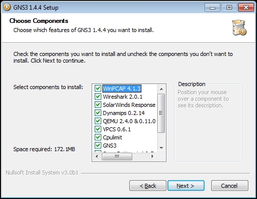
GNS3 components
After several clicks on the Next button, we will have a working network virtualization platform.
In our case, we are using Microsoft Windows 8.1 as a host operating system, so the installation process flows as described. But GNS3 is a multiplatform software, so you can also use it on Linux systems where the installation process is different but simple too. For example, GNS3 is available in repositories of Ubuntu or Debian and to install it you should just execute the command:
sudo apt-get install gns3
Note
If you want to install GNS3 on Mac OS X, you can find a detailed installation guide at the official website: https://gns3.com/support/docs/quick-start-guide-for-mac-users.
So, it is time for starting and configuring our virtualization platform. For that purpose, let's find the shortcut for GNS3 on the desktop and execute it. When the application starts, you'll be prompted to save a new project.
After entering the name of the project, the application will open a working user interface of our virtual environment:

The GNS3 user interface
To set up the program, let's go to Edit | Preferences. Now, we can configure the working environment for own convenience. In the General tab, we can choose the paths for saving working files, the styles and display settings of the interface, and the most important thing at this tab is the console emulation software and its settings. But since we are using Microsoft Windows as the host OS, we leave the defaults (PuTTY). In the Server tab, we can change the server component parameters of GNS3, for example, the connection parameters of a remote server. But at this step, we leave defaults. In the Packet capture tab, we can configure our connection to the network traffic analyzer. In the VPCS tab, we can choose how to use host stubs. Host stubs can be used to validate network schema (for example, ping, tracert, and so on). The default application is installed with GNS3. Here, we can leave the default settings. In the VirtualBox tab, we should set paths to the VirtualBox management application (VBoxManage.exe). We won't use the tabs IOS on Unix and QEMU in our lab, so we will leave these tabs without changes too.
What we need to do now is to add the Cisco IOS images in the list of used devices (if we have already obtained IOS images). This can be done in the Dynamips tab. At this step, we need to create two virtual devices: switch and gateway. After clicking on the New button, it will start the wizard for creating a virtual device. In the beginning, we are invited to enter the path to the IOS image file. After that, the image file will be decompressed and will be followed by a series of questions about the device. The specification of the platform should be recognized automatically. RAM should be left at the default value. On the Network adapters page, you should select the adapters that will be used and their slots.
For the virtual switch device, we should select the switched network adapter. In GNS3, it is NM-16ESW. In our case, we use slot 0. You can choose another, but we recommend you to use the same one to match with the hardware configuration case described earlier. For the virtual gateway device, we should select the interface with 1 port, for example, NM-1FE-TX, and put it in slot 0.
The last thing to address is the Idle PC value; at this step, leave this field blank:

Virtual IOS devices
So, after these manipulations, we will have two virtual Cisco IOS instances in the list of available devices.
Next, let's implement our network topology in the GNS3 workspace. The process of designing a network diagram is similar to any other designing system: select device icons and drag them to the workspace. After that, connect network interfaces of the devices with each other using the Add a link tool.
In our case, the result is similar to the following screenshot:
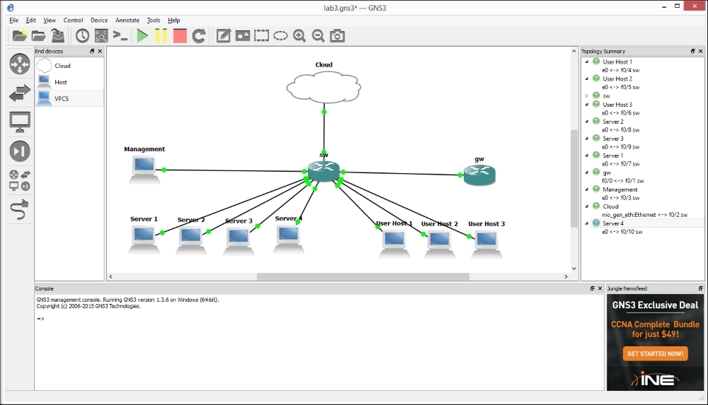
The network diagram
Now, we use stubs VPCS as hosts. The switch and the router are our Cisco IOS devices created earlier based on IOS images for Dynamips. For connections with a SOHO router and a hardware AP, we use the tool called Cloud.
To match with the hardware configuration case described earlier, connections between interfaces should be as follows:
|
Functional group |
Connection type |
Device |
Interface |
|---|---|---|---|
|
Servers |
|
SW |
|
|
User hosts |
|
SW |
|
|
Management |
|
SW |
|
|
Cloud |
|
SW |
|
|
GW |
|
SW |
|
After all the components are placed in the project workspace, we need to fill in the field Idle PC of our IOS devices. The parameter Idle PC allows us to significantly reduce the CPU usage, but it can be changed only if the device is running. Thus we need to start these network devices by clicking on the button Start devices placed on the toolbar of the main window, or by clicking on the item Start in the context menu of the device. For each IOS device, we need to select the item Idle PC in the context menu and in appeared dialog we should select the value marked by an asterisk.
Interaction with the device is performed via the console. For this, we just need to right-click on the device icon in the project workspace and select Console from the context menu. After that, the terminal emulator will be launched with the established connection.
So, let's create the config for our core switch. First of all, we set the hostname:
config t
 hostname sw
 exit
Then we create the VLANs:
vlan database
 vlan 2 name servers
 vlan 3 name users
 vlan 4 name trusted_wlan
 vlan 5 name external_network
 exit
In the next step, we set up the interfaces, set one trunk port to the router, and set the access ports for network hosts:
config t
!
interface fa0/1
 switchport mode trunk
 description router trunk
 no shutdown
!
interface fa0/2
 switchport mode access
 switchport access vlan 5
 description external network
 no shutdown
!
interface fa0/3
 switchport mode access
 switchport access vlan 1
 no shutdown
!
interface fa0/4
 switchport mode access
 switchport access vlan 3
 no shutdown
!
interface fa0/5
 switchport mode access
 switchport access vlan 3
 no shutdown
!
interface fa0/6
 switchport mode access
 switchport access vlan 3
 no shutdown
!
interface fa0/7
 switchport mode access
 switchport access vlan 2
 no shutdown
!
interface fa0/8
 switchport mode access
 switchport access vlan 2
 no shutdown
!
interface fa0/9
 switchport mode access
 switchport access vlan 2
 no shutdown
!
interface fa0/10
 switchport mode access
 switchport access vlan 2
 no shutdown
!
interface fa0/11
 switchport mode access
 switchport access vlan 2
 description IDS
 no shutdown
!
interface fa0/12
 switchport mode access
 switchport access vlan 4
 description Trusted WLAN
 no shutdown
exit
As you can see, the work with the virtual network device corresponds to the work with the hardware configuration case; there is a little difference in the way how physical devices are connected to each other.
If you work with virtual network devices, it is not so important to properly harden them like hardware devices.
There is no significant difference in configuring hardware and virtual devices; therefore, we do the same as we did in the case of hardware configuration:
interface fa0/0.1
 encapsulation dot1Q 1
 ip address 10.1.0.1 255.255.255.0
!
interface fa0/0.2
 encapsulation dot1Q 2
 ip address 10.0.0.1 255.255.255.0
!
interface fa0/0.3
 encapsulation dot1Q 3
 ip address 172.16.0.1 255.255.255.0
!
interface fa0/0.4
 encapsulation dot1Q 4
 ip address 172.16.1.1 255.255.255.0

interface fa0/0
 no shutdown

ip dhcp pool users
 network 172.16.0.0 255.255.255.0
 dns-server 172.16.0.1 8.8.8.8
 default-router 172.16.0.1
!
ip dhcp pool trusted
 network 172.16.1.0 255.255.255.0
 dns-server 172.16.1.1 8.8.8.8
 default-router 172.16.1.1

!interface fa0/0.1
 ip nat inside
!
interface fa0/0.2
 ip nat inside
!
interface fa0/0.3
 ip nat inside
!
interface fa0/0.4
 ip nat inside
!
interface fa0/0.5
 ip address dhcp
 ip nat outside
 ip nat inside source list 102 interface Ethernet1 overload

 ip classless
 ip route 0.0.0.0 0.0.0.0 192.168.0.1
Now, we need to check our virtual network's working capacity with host emulators. We will show you how to connect VirtualBox VMs to the virtual network in the next chapter, but at the moment the functionality of emulators is enough for testing purposes.
Such emulators are already provided by GNS; they are stubs of the type VPCS. These virtual devices allow us to perform basic operations for emulating real devices based on IP connections (ICMP ping and TCP/UDP connections). The interaction with such devices is done by the console and manual input of commands. In our case, for setting up addresses in the device console, we just need to input a command:
ip dhcp
Of course, we can use static addresses for this purpose in the device console input command:
ip 10.0.0.101 255.255.255.0 10.0.0.1
Where:
- 10.0.0.101 is the host address
- 255.255.255.0 is the network mask
- 10.0.0.1 is the gateway address
For testing network connectivity and operability, we can use the ICMP-based commands ping and tracert:
ping 10.0.0.1
tracert 10.0.0.1
Note
Using GNS, we can also easily capture network traffic, for example, with Wireshark.
You need to do the following:
1) Right-click on the link between the two devices.
2) Choose the item Сapture from the context menu.
3) After that, Wireshark will start (or another application that was set in the Packet capture tab of GNS3 preferences).
In the Wireshark window, we will have all the intercepted packets.
The only type of network device that we cannot virtualize is a wireless access points. Therefore, we will use the physical network devices. As in the case of hardware configuration, it will be an access point and a SOHO router.
For interaction with the external world, GNS3 provides a tool Cloud, which is the built-in connector between the GNS3 virtual infrastructure and the network adapter of the host computer.
If your host computer has two Ethernet adapters, you can use two clouds to connect to each physical device. But if your host computer is a laptop, as in our case, you can use an Ethernet adapter for connecting to the SOHO router and use the wireless adapter of your host computer as the access point instead of a hardware access point.
If you have only one Ethernet adapter and still do not want to use the wireless adapter of the host computer, you have two options:
- Manually switching between hardware devices (AP and SOHO router)
- Preparing an additional VM with a software AP and a USB Wi-Fi interface connected to it using the USB-forwarding feature of VirtualBox (we briefly show how to install the necessary software and implement such a scenario in Chapter 7, Preparing a Wireless Penetration Testing Platform)
Now, let's see how to connect a network adapter of the host computer to our virtual infrastructure.
Right-click on the icon of the Сloud tool and open the configuration window of Cloud by selecting Configure from the context menu. We should specify the network adapter that we want to use in the field Ethernet NIO in the configuration window by navigating to Cloud | Ethernet. After that, click on the button Add.

The Cloud configuration window
Now, Cloud is configured. Quite simple, isn't it?