Chapter 18. Troubleshooting IPv4 Routing
This chapter covers the following exam topics:
1.0 Network Fundamentals
1.6 Configure and verify IPv4 addressing and subnetting
3.0 IP Connectivity
3.3 Configure and verify IPv4 and IPv6 static routing
3.3.a Default route
3.3.b Network route
3.3.c Host route
3.3.d Floating static
The first three chapters in this part of the book took you from a starting point of understanding IP addressing and subnetting to the details of implementing IP addressing, routing between connected subnets, and configuring static routes. All those steps include the idea of configuring a command and seeing a route show up in the IP routing table on that same router.
This chapter turns our attention to routing from end-to-end across an entire enterprise network. How do you troubleshoot an IPv4 network? How do you verify correct operation, identify root causes, and fix those for various IP routing features? How do you do that in the presence of an IP addressing and subnetting plan, requiring you to apply all that subnetting math from Part IV of this book and the basic address/mask and static route configuration from the other chapters here in Part V? This chapter answers some of those questions.
In particular, this chapter focuses on two tools and how to use them: ping and traceroute. Both tools test the IPv4 data plane; that is, the ability of each networking device to route or forward IPv4 packets. This chapter devotes a major section each to ping and traceroute. The chapter then ends with a short discussion of two other router tools that can also be useful for troubleshooting: Telnet and Secure Shell (SSH).
“Do I Know This Already?” Quiz
I put DIKTA quizzes in most of the chapters as a tool to help you decide how to approach reading a chapter. However, this chapter does not have a DIKTA quiz because I think you should read it regardless of your prior knowledge. As with all chapters in this book, this chapter introduces new concepts, but it also acts as a tool to review and deepen your understanding of IP routing. I hope you enjoy the perspectives on using ping and traceroute in this chapter.
Foundation Topics
Problem Isolation Using the ping Command
Someone sends you an email or text, or a phone message, asking you to look into a user’s network problem. You Secure Shell (SSH) to a router and issue a ping command that works. What does that result rule out as a possible reason for the problem? What does it rule in as still being a possible root cause?
Then you issue another ping to another address, and this time the ping fails. Again, what does the failure of that ping command tell you? What parts of IPv4 routing may still be a problem, and what parts do you now know are not a problem?
The ping command gives us one of the most common network troubleshooting tools. When the ping command succeeds, it confirms many individual parts of how IP routing works, ruling out some possible causes of the current problem. When a ping command fails, it often helps narrow down where in the internetwork the root cause of the problem may be happening, further isolating the problem.
This section begins with a brief explanation of how ping works. It then moves on to some suggestions and analysis of how to use the ping command to isolate problems by removing some items from consideration.
Ping Command Basics
The ping command tests connectivity by sending packets to an IP address, expecting the device at that address to send packets back. The command sends packets that mean “if you receive this packet, and it is addressed to you, send a reply back.” Each time the ping command sends one of these packets and receives the message sent back by the other host, the ping command knows a packet made it from the source host to the destination and back.
More formally, the ping command uses the Internet Control Message Protocol (ICMP), specifically the ICMP echo request and ICMP echo reply messages. ICMP defines many other messages as well, but these two messages were made specifically for connectivity testing by commands like ping. As a protocol, ICMP does not rely on TCP or UDP, and it does not use any application layer protocol. It functions as part of Layer 3, as a control protocol to assist IP by helping manage the IP network functions.
Figure 18-1 shows the ICMP messages, with IP headers, in an example. In this case, the user at host A opens a command prompt and issues the ping 172.16.2.101 command, testing connectivity to host B. The command sends one echo request and waits (Step 1); host B receives the messages and sends back an echo reply (Step 2).

Figure 18-1 Concept Behind ping 172.16.2.101 on Host A
The ping command is supported on many different devices and many common operating systems. The command has many options: the name or IP address of the destination, how many times the command should send an echo request, how long the command should wait (timeout) for an echo reply, how big to make the packets, and many other options. Example 18-1 shows a sample from host A, with the same command that matches the concept in Figure 18-1: a ping 172.16.2.101 command on host A.
Example 18-1 Sample Output from Host A’s ping 172.16.2.101 Command
Wendell-Odoms-iMac:~ wendellodom$ ping 172.16.2.101
PING 172.16.2.101 (172.16.2.101): 56 data bytes
64 bytes from 172.16.2.101: icmp_seq=0 ttl=64 time=1.112 ms
64 bytes from 172.16.2.101: icmp_seq=1 ttl=64 time=0.673 ms
64 bytes from 172.16.2.101: icmp_seq=2 ttl=64 time=0.631 ms
64 bytes from 172.16.2.101: icmp_seq=3 ttl=64 time=0.674 ms
64 bytes from 172.16.2.101: icmp_seq=4 ttl=64 time=0.642 ms
64 bytes from 172.16.2.101: icmp_seq=5 ttl=64 time=0.656 ms
^C
--- 172.16.2.101 ping statistics ---
6 packets transmitted, 6 packets received, 0.0% packet loss
round-trip min/avg/max/stddev = 0.631/0.731/1.112/0.171 ms
Strategies and Results When Testing with the ping Command
Often, the person handling initial calls from users about problems (often called a customer support rep, or CSR) cannot issue ping commands from the user’s device. In some cases, talking users through typing the right commands and making the right clicks on their machines can be a problem. Or, the user just might not be available. As an alternative, using different ping commands from different routers can help isolate the problem.
The problem with using ping commands from routers, instead of from the host that has the problem, is that no single router ping command can exactly replicate a ping command done from the user’s device. However, each different ping command can help isolate a problem further. The rest of this section of ping commands discusses troubleshooting IPv4 routing by using various ping commands from the command-line interface (CLI) of a router.
Testing Longer Routes from Near the Source of the Problem
Most problems begin with some idea like “host X cannot communicate with host Y.” A great first troubleshooting step is to issue a ping command from X for host Y’s IP address. However, assuming the engineer does not have access to host X, the engineer can instead issue the ping from the router nearest X, typically the router acting as host X’s default gateway.
For instance, in Figure 18-1, imagine that the user of host A had called IT support with a problem related to sending packets to host B. A ping 172.16.2.101 command on host A would be a great first troubleshooting step, but the CSR cannot access host A or get in touch with the user of host A. So, the CSR telnets to Router R1 and pings host B from there, as shown in Example 18-2.
Example 18-2 Router R2 Pings Host B (Two Commands)
R1# ping 172.16.2.101
Type escape sequence to abort.
Sending 5, 100-byte ICMP Echos to 172.16.2.101, timeout is 2 seconds:
.!!!!
Success rate is 80 percent (4/5), round-trip min/avg/max = 1/2/4 ms
R1# ping 172.16.2.101
Type escape sequence to abort.
Sending 5, 100-byte ICMP Echos to 172.16.2.101, timeout is 2 seconds:
!!!!!
Success rate is 100 percent (5/5), round-trip min/avg/max = 1/2/4 ms
First, take a moment to review the output of the first IOS ping command. By default, the Cisco IOS ping command sends five echo messages, with a timeout of 2 seconds. If the command does not receive an echo reply within 2 seconds, the command considers that message to be a failure, and the command lists a period. If a successful reply is received within 2 seconds, the command displays an exclamation point. So, in this first command, the first echo reply timed out, whereas the other four received a matching echo reply within 2 seconds.
As a quick aside, the example shows a common and normal behavior with ping commands: the first ping command shows one failure to start, but then the rest of the messages work. This usually happens because some device in the end-to-end route is missing an ARP table entry.
Now think about troubleshooting and what a working ping command tells us about the current behavior of this internetwork. First, focus on the big picture for a moment:
R1 can send ICMP echo request messages to host B (172.16.2.101).
R1 sends these messages from its outgoing interface’s IP address (by default), 172.16.4.1 in this case.
Host B can send ICMP echo reply messages to R1’s 172.16.4.1 IP address (hosts send echo reply messages to the IP address from which the echo request was received).
Figure 18-2 shows the packet flow.
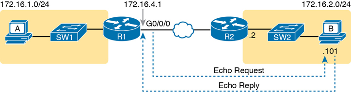
Figure 18-2 Standard ping 172.6.2.101 Command Using the Source Interface IP Address
Next, think about IPv4 routing. In the forward direction, R1 must have a route that matches host B’s address (172.16.2.101); this route will be either a static route or one learned with a routing protocol. R2 also needs a route for host B’s address, in this case a connected route to B’s subnet (172.16.2.0/24), as shown in the top arrow lines in Figure 18-3.
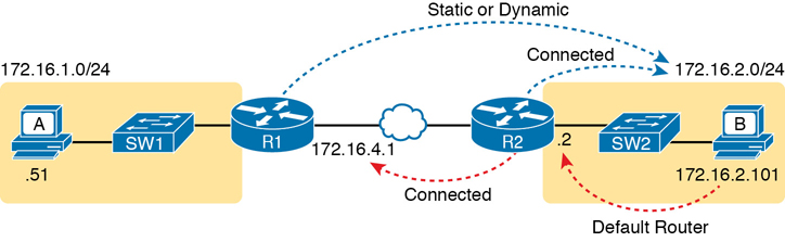
Figure 18-3 Layer 3 Routes Needed for R1’s Ping 172.16.2.101 to Work
The arrow lines on the bottom of Figure 18-3 show the routes needed to forward the ICMP echo reply message back to Router R1’s 172.16.4.1 interface. First, host B must have a valid default router setting because 172.16.4.1 sits in a different subnet than host B. R2 must also have a route that matches destination 172.16.4.1 (in this case, likely to be a connected route).
The working ping commands in Example 18-2 also require the data-link and physical layer details to be working. The WAN link must be working: The router interfaces must be up/up, which typically indicates that the link can pass data. On the LAN, R2’s LAN interface must be in an up/up state. In addition, everything discussed about Ethernet LANs must be working because the ping confirmed that the packets went all the way from R1 to host B and back. In particular
The switch interfaces in use are in a connected (up/up) state.
Port security (discussed in the CCNA 200-301 Official Cert Guide, Volume 2) does not filter frames sent by R2 or host B.
STP has placed the right ports into a forwarding state.
The ping 172.16.2.101 command in Example 18-2 also confirms that IP access control lists (ACL) did not filter the ICMP messages. One ACL contains a set of matching rules and actions: some matched packets are filtered (discarded), while others can continue on their path as normal. ACLs can examine packets as they enter or exit a router interface, so Figure 18-4 shows the various locations on routers R1 and R2 where an ACL could have filtered (discarded) the ICMP messages. (Note that an outbound ACL on router R1 would not filter packets created on R1, so there is no rightward-facing arrow over R1.)
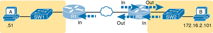
Figure 18-4 Locations Where IP ACLs Could Have Filtered the Ping Messages
Finally, the working ping 172.16.2.101 command on R1 can also be used to reasonably predict that ARP worked and that switch SW2 learned MAC addresses for its MAC address table. R2 and host B need to know each other’s MAC addresses so that they can encapsulate the IP packet inside an Ethernet frame, which means both must have a matching ARP table entry. The switch learns the MAC address used by R2 and by host B when it sends the ARP messages or when it sends the frames that hold the IP packets. Figure 18-5 shows the type of information expected in those tables.
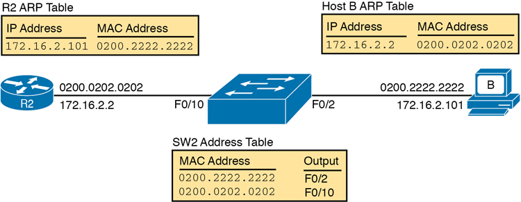
Figure 18-5 Router and Host ARP Tables, with the Switch MAC Address Table
As you can see from the last few pages, a strategy of using a ping command from near the source of the problem can rule out a lot of possible root causes of any problems between two hosts—assuming the ping command succeeds. However, this ping command does not act exactly like the same ping command on the actual host. To overcome some of what is missing in the ping command from a nearby router, the next several examples show some strategies for testing other parts of the path between the two hosts that might have a current problem.
Using Extended Ping to Test the Reverse Route
Pinging from the default router, as discussed in the past few pages, misses an opportunity to test IP routes more fully. In particular, it does not test the reverse route back toward the original host.
For instance, referring to the internetwork in Figure 18-2 again, note that the reverse routes do not point to an address in host A’s subnet. When R1 processes the ping 172.16.2.101 command, R1 has to pick a source IP address to use for the echo request, and routers choose the IP address of the outgoing interface. The echo request from R1 to host B flows with source IP address 172.16.4.1 (R1’s G0/0/0 IP address). The echo reply flows back to that same address (172.16.4.1).
A standard ping often does not test the reverse route that you need to test. In this case, the standard ping 172.16.2.101 command on R1 does not test whether the routers can route back to subnet 172.16.1.0/24, instead testing their routes for subnet172.16.4.0. A better ping test would test the route back to host A’s subnet; an extended ping from R1 can cause that test to happen. Extended ping allows R1’s ping command to use R1’s LAN IP address from within subnet 172.16.1.0/24. Then, the echo reply messages would flow to host A’s subnet, as shown in Figure 18-6.


Figure 18-6 Extended Ping Command Tests the Route to 172.16.1.51 (Host A)
The extended ping command does allow the user to type all the parameters on a potentially long command, but it also allows users to simply issue the ping command, press Enter, with IOS then asking the user to answer questions to complete the command, as shown in Example 18-3. The example shows the ping command on R1 that matches the logic in Figure 18-6. This same command could have been issued from the command line as ping 172.16.2.101 source 172.16.1.1.
Example 18-3 Testing the Reverse Route Using the Extended Ping
R1# ping
Protocol [ip]:
Target IP address: 172.16.2.101
Repeat count [5]:
Datagram size [100]:
Timeout in seconds [2]:
Extended commands [n]: y
Source address or interface: 172.16.1.1
Type of service [0]:
Set DF bit in IP header? [no]:
Validate reply data? [no]:
Data pattern [0xABCD]:
Loose, Strict, Record, Timestamp, Verbose[none]:
Sweep range of sizes [n]:
Type escape sequence to abort.
Sending 5, 100-byte ICMP Echos to 172.16.2.101, timeout is 2 seconds:
Packet sent with a source address of 172.16.1.1
!!!!!
Success rate is 100 percent (5/5), round-trip min/avg/max = 1/2/4 ms
This particular extended ping command tests the same routes for the echo request going to the right, but it forces a better test of routes pointing back to the left for the ICMP echo reply. For that direction, R2 needs a route that matches address 172.16.1.1, which is likely to be a route for subnet 172.16.1.0/24—the same subnet in which host A resides.
From a troubleshooting perspective, using both standard and extended ping commands can be useful. However, neither can exactly mimic a ping command created on the host itself because the routers cannot send packets with the host’s IP address. For instance, the extended ping in Example 18-3 uses source IP address 172.16.1.1, which is not host A’s IP address. As a result, neither the standard or extended ping commands in these two examples so far in this chapter can test for some kinds of problems, such as the following:
IP ACLs that discard packets based on host A’s IP address but allow packets that match the router’s IP address
LAN switch port security that filters A’s frames (based on A’s MAC address)
IP routes on routers that happen to match host A’s 172.16.1.51 address, with different routes that match R1’s 172.16.1.1 address
Problems with host A’s default router setting
Note
IP ACLs and LAN switch port security are covered in CCNA 200-301 Official Cert Guide, Volume 2. For now, know that IP ACLs can filter packets on routers, focusing on the Layer 3 and 4 headers. Port security can be enabled on Layer 2 switches to filter based on source MAC addresses.
Testing LAN Neighbors with Standard Ping
Testing using a ping of another device on the LAN can quickly confirm whether the LAN can pass packets and frames. Specifically, a working ping rules out many possible root causes of a problem. For instance, Figure 18-7 shows the ICMP messages that occur if R1 issues the command ping 172.16.1.51, pinging host A, which sits on the same VLAN as R1.
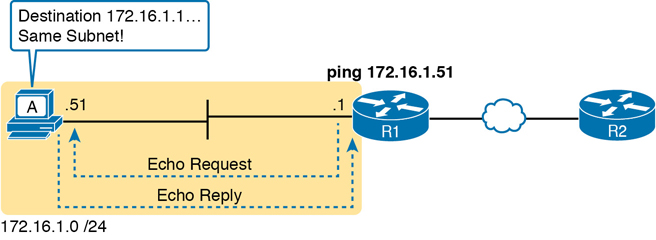
Figure 18-7 Standard ping Command Confirms That the LAN Works
If the ping works, it confirms the following, which rules out some potential issues:
The host with address 172.16.1.51 replied.
The LAN can pass unicast frames from R1 to host 172.16.1.51 and vice versa.
You can reasonably assume that the switches learned the MAC addresses of the router and the host, adding those to the MAC address tables.
Host A and Router R1 completed the ARP process and list each other in their respective Address Resolution Protocol (ARP) tables.
The failure of a ping, even with two devices on the same subnet, can point to a variety of problems, like those mentioned in this list. For instance, if the ping 172.16.1.51 on R1 fails (Figure 18-7), that result points to this list of potential root causes:
IP addressing problem: Host A could be statically configured with the wrong IP address.
DHCP problems: If you are using Dynamic Host Configuration Protocol (DHCP), many problems could exist. Chapter 7, “Implementing DHCP” in CCNA 200-301 Official Cert Guide, Volume 2, discusses those possibilities in some depth.
VLAN trunking problems: The router could be configured for 802.1Q trunking, when the switch is not (or vice versa).
LAN problems: A wide variety of issues could exist with the Layer 2 switches, preventing any frames from flowing between host A and the router.
So, whether the ping works or fails, simply pinging a LAN host from a router can help further isolate the problem.
Testing LAN Neighbors with Extended Ping
A standard ping of a LAN host from a router does not test that host’s default router setting. However, an extended ping can test the host’s default router setting. Both tests can be useful, especially for problem isolation, because
If a standard ping of a local LAN host works…
But an extended ping of the same LAN host fails…
The problem likely relates somehow to the host’s default router setting.
First, to understand why the standard and extended ping results have different effects, consider first the standard ping 172.16.1.51 command on R1, as shown previously in Figure 18-7. As a standard ping command, R1 used its LAN interface IP address (172.16.1.1) as the source of the ICMP Echo. So, when the host (A) sent back its ICMP echo reply, host A considered the destination of 172.16.1.1 as being on the same subnet. Host A’s ICMP echo reply message, sent back to 172.16.1.1, would work even if host A did not have a default router setting at all!
In comparison, Figure 18-8 shows the difference when using an extended ping on Router R1. An extended ping from local Router R1, using R1’s S0/0/0 IP address of 172.16.4.1 as the source of the ICMP echo request, means that host A’s ICMP echo reply will flow to an address in another subnet, which makes host A use its default router setting.
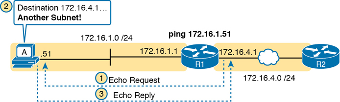
Figure 18-8 Extended ping Command Does Test Host A’s Default Router Setting
The comparison between the previous two figures shows one of the most classic mistakes when troubleshooting networks. Sometimes, the temptation is to connect to a router and ping the host on the attached LAN, and it works. So, the engineer moves on, thinking that the network layer issues between the router and host work fine, when the problem still exists with the host’s default router setting.
Testing WAN Neighbors with Standard Ping
As with a standard ping test across a LAN, a standard ping test between routers over a serial or Ethernet WAN link tests whether the link can pass IPv4 packets. With a properly designed IPv4 addressing plan, two routers on the same serial or Ethernet WAN link should have IP addresses in the same subnet. A ping from one router to the IP address of the other router confirms that an IP packet can be sent over the link and back, as shown in the ping 172.16.4.2 command on R1 in Figure 18-9.
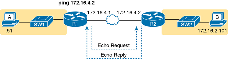
Figure 18-9 Pinging Across a WAN Link
A successful ping of the IP address on the other end of an Ethernet WAN link that sits between two routers confirms several specific facts, such as the following:
Both routers’ WAN interfaces are in an up/up state.
The Layer 1 and 2 features of the link work.
The routers believe that the neighboring router’s IP address is in the same subnet.
Inbound ACLs on both routers do not filter the incoming packets, respectively.
The remote router is configured with the expected IP address (172.16.4.2 in this case).
Testing by pinging the other neighboring router does not test many other features. However, although the test is limited in scope, it does let you rule out WAN links as having a Layer 1 or 2 problem, and it rules out some basic Layer 3 addressing problems.
Using Ping with Names and with IP Addresses
All the ping examples so far in this chapter show a ping of an IP address. However, the ping command can use hostnames, and pinging a hostname allows the network engineer to further test whether the Domain Name System (DNS) process works.
First, most every TCP/IP application today uses hostnames rather than IP addresses to identify the other device. No one opens a web browser and types in 72.163.4.185. Instead, they type in a web address, like www.cisco.com, which includes the hostname www.cisco.com. Then, before a host can send data to a specific IP address, the host must first ask a DNS server to resolve that hostname into the matching IP address.
For example, in the small internetwork used for several examples in this chapter, a ping B command on host A tests A’s DNS settings, as shown in Figure 18-10. When host A sees the use of a hostname (B), it first looks in its local DNS name cache to find out whether it has already resolved the name B. If not, host A first asks the DNS to supply (resolve) the name into its matching IP address (Step 1 in the figure). Only then does host A send a packet to 172.16.2.101, host B’s IP address (Step 2).
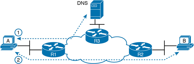
Figure 18-10 DNS Name Resolution by Host A
When troubleshooting, testing from the host by pinging using a hostname can be very helpful. The command, of course, tests the host’s own DNS client settings. For instance, a classic comparison is to first ping the destination host using the hostname, which requires a DNS request. Then, repeat the same test, but use the destination host’s IP address instead of its name, which does not require the DNS request. If the ping of the hostname fails but the ping of the IP address works, the problem usually has something to do with DNS.
Problem Isolation Using the traceroute Command
Like ping, the traceroute command helps network engineers isolate problems. Here is a comparison of the two:
Both send messages in the network to test connectivity.
Both rely on other devices to send back a reply.
Both have wide support on many different operating systems.
Both can use a hostname or an IP address to identify the destination.
On routers, both have a standard and extended version, allowing better testing of the reverse route.
The biggest differences relate to the more detailed results in the output of the traceroute command and the extra time and effort it takes traceroute to build that output. This second major section examines how traceroute works; plus it provides some suggestions on how to use this more detailed information to more quickly isolate IP routing problems.
traceroute Basics
Imagine some network engineer or CSR starts to troubleshoot some problem. The engineer pings from the user’s host, pings from a nearby router, and after a few commands, convinces herself that the host can indeed send and receive IP packets. The problem might not be solved yet, but the problem does not appear to be a network problem.
Now imagine the next problem comes along, and this time the ping command fails. It appears that some problem does exist in the IP network. Where is the problem? Where should the engineer look more closely? Although the ping command can prove helpful in isolating the source of the problem, the traceroute command may be a better option. The traceroute command systematically helps pinpoint routing problems by showing how far a packet goes through an IP network before being discarded.
The traceroute command identifies the routers in the path from source host to destination host. Specifically, it lists the next-hop IP address of each router that would be in each of the individual routes. For instance, a traceroute 172.16.2.101 command on host A in Figure 18-11 would identify an IP address on Router R1, another on Router R2, and then host B, as shown in the figure. Example 18-4, which follows, lists the output of the command, taken from host A.
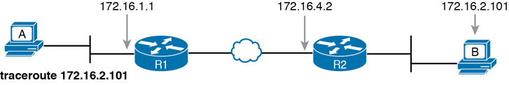
Figure 18-11 IP Addresses Identified by a Successful traceroute 172.16.2.101 Command
Example 18-4 Output from traceroute 172.16.2.101 on Host A
Wendell-Odoms-iMac:~ wendellodom$ traceroute 172.16.2.101
traceroute to 172.16.2.101, 64 hops max, 52 byte packets
  1 172.16.1.1 (172.16.1.1) 0.870 ms 0.520 ms 0.496 ms
  2 172.16.4.2 (172.16.4.2) 8.263 ms 7.518 ms 9.319 ms
  3 172.16.2.101 (172.16.2.101) 16.770 ms 9.819 ms 9.830 ms
How the traceroute Command Works
The traceroute command gathers information by generating packets that trigger error messages from routers; these messages identify the routers, letting the traceroute command list the routers’ IP addresses in the output of the command. That error message is the ICMP Time-to-Live Exceeded (TTL Exceeded) message, originally meant to notify hosts when a packet had been looping around a network.
Ignoring traceroute for a moment and instead focusing on IP routing, IPv4 routers defeat routing loops in part by discarding looping IP packets. To do so, the IPv4 header holds a field called Time To Live (TTL). The original host that creates the packet sets an initial TTL value. Then each router that forwards the packet decrements the TTL value by 1. When a router decrements the TTL to 0, the router perceives the packet is looping, and the router discards the packet. The router also notifies the host that sent the discarded packet by sending an ICMP TTL Exceeded message.
Now back to traceroute. Traceroute sends messages with low TTL values to make the routers send back a TTL Exceeded message. Specifically, a traceroute command begins by sending several packets (usually three), each with the header TTL field equal to 1. When that packet arrives at the next router—host A’s default Router R1 in the example of Figure 18-12—the router decrements TTL to 0 and discards the packet. The router then sends host A the TTL Exceeded message, which identifies the router’s IP address to the traceroute command.
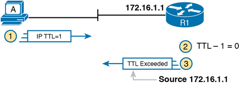
Figure 18-12 How traceroute Identifies the First Router in the Route
The traceroute command sends several TTL=1 packets, checking them to see whether the TTL Exceeded messages flow from the same router, based on the source IP address of the TTL Exceeded message. Assuming the messages come from the same router, the traceroute command lists that IP address as the next line of output on the command.
To find all the routers in the path, and finally confirm that packets flow all the way to the destination host, the traceroute command sends a small set of packets with TTL=1, then a small set with TTL=2, then 3, 4, and so on, until the destination host replies. Figure 18-13 shows the packet from the second set with TTL=2. In this case, one router (R1) actually forwards the packet, while another router (R2) happens to decrement the TTL to 0, causing a TTL Exceeded message to be sent back to host A.
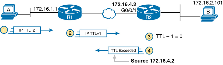
Figure 18-13 TTL=2 Message Sent by traceroute
The figure shows these four steps:
The traceroute command sends a packet from the second set with TTL=2.
Router R1 processes the packet and decrements TTL to 1. R1 forwards the packet.
Router R2 processes the packet and decrements TTL to 0. R2 discards the packet.
R2 notifies the sending host of the discarded packet by sending a TTL Exceeded ICMP message. The source IP address of that message is 172.16.4.2.
Finally, the choice of source IP address to use on the time-exceeded message returned by routers has a big impact on the output of the traceroute command. Most routers use simpler logic that also makes command output like traceroute more consistent and meaningful. That logic: choose the TTL Exceeded message’s source IP address based on the source interface of the original message that was discarded due to TTL. In the example in Figure 18-13, the original message at Step 2 arrived on R2’s G0/0/1 interface, so at Step 3, R2 uses G0/0/1’s IP address as the source IP address of the TTL Exceeded message, and as the interface out which to send the message.
Standard and Extended traceroute
The standard and extended options for the traceroute command give you many of the same options as the ping command. For instance, Example 18-5 lists the output of a standard traceroute command on Router R1. Like the standard ping command, a standard traceroute command chooses an IP address based on the outgoing interface for the packet sent by the command. So, in this example, the packets sent by R1 come from source IP address 172.16.4.1, R1’s G0/0/0 IP address.
Example 18-5 Standard traceroute Command on R1
R1# traceroute 172.16.2.101
Type escape sequence to abort.
Tracing the route to 172.16.2.101
VRF info: (vrf in name/id, vrf out name/id)
   1 172.16.4.2 0 msec 0 msec 0 msec
   2 172.16.2.101 0 msec 0 msec *
The extended traceroute command, as shown in Example 18-6, follows the same basic command structure as the extended ping command. The user can type all the parameters on one command line, but it is much easier to just type traceroute, press Enter, and let IOS prompt for all the parameters, including the source IP address of the packets (172.16.1.1 in this example).
Example 18-6 Extended traceroute Command on R1
R1# traceroute
Protocol [ip]:
Target IP address: 172.16.2.101
Source address: 172.16.1.1
Numeric display [n]:
Timeout in seconds [3]:
Probe count [3]:
Minimum Time to Live [1]:
Maximum Time to Live [30]:
Port Number [33434]:
Loose, Strict, Record, Timestamp, Verbose[none]:
Type escape sequence to abort.
Tracing the route to 172.16.2.101
VRF info: (vrf in name/id, vrf out name/id)
   1 172.16.4.2 0 msec 0 msec 0 msec
   2 172.16.2.101 0 msec 0 msec *
Both the ping and traceroute commands exist on most operating systems, including Cisco IOS. However, some operating systems use a slightly different syntax for traceroute. For example, most Windows operating systems support tracert and pathping, and not traceroute. Linux and OS X support the traceroute command.
Note
Host OS traceroute commands usually create ICMP echo requests. The Cisco IOS traceroute command instead creates IP packets with a UDP header. This bit of information may seem trivial at this point. However, note that an ACL may actually filter the traffic from a host’s traceroute messages but not the router traceroute command, or vice versa.
Telnet and SSH
The ping and traceroute commands do give networkers two great tools to begin isolating the cause of an IP routing problem. However, these two commands tell us nothing about the operation state inside the various network devices. Once you begin to get an idea of the kinds of problems and the possible locations of the problems using ping and traceroute, the next step is to look at the status of various router and switch features. One way to do that is to use Telnet or Secure Shell (SSH) to log in to the devices.
Common Reasons to Use the IOS Telnet and SSH Client
Normally, a network engineer would log in to the remote device using a Telnet or SSH client on a PC, tablet, or any other user device. In fact, often, the same software package does both Telnet and SSH. However, in some cases, you may want to take advantage of the Telnet and SSH client built in to IOS on the routers and switches to Telnet/SSH from one Cisco device to the next.
To understand why, consider the example shown in Figure 18-14. The figure shows arrowed lines to three separate IP addresses on three separate Cisco routers. PC1 has attempted to Telnet to each address from a different tab in PC1’s Telnet/SSH client. However, R2 happens to have an error in its routing protocol configuration, so R1, R2, and R3 fail to learn any routes from each other. As a result, PC1’s Telnet attempt to both 10.1.2.2 (R2) and 10.1.3.3 (R3) fails.
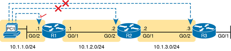
Figure 18-14 Telnet Works from PC1 to R1 but Not to R2 or R3
In some cases, like this one, a Telnet or SSH login from the network engineer’s device can fail, while you could still find a way to log in using the telnet and ssh commands to use the Telnet and SSH clients on the routers or switches. With this particular scenario, all the individual data links work; the problem is with the routing protocol exchanging routes. PC1 can ping R1’s 10.1.1.1 IP address, R1 can ping R2’s 10.1.2.2 address, and R2 can ping R3’s 10.1.3.3 address. Because each link works, and each router can send and receive packets with its neighbor on the shared data link, you could Telnet/SSH to each successive device.
Figure 18-15 shows the idea. On the left, PC1 begins with either a Telnet/SSH or a console connection into Router R1, as shown on the left. Then the user issues the telnet 10.1.2.2 command from R1 to Telnet to R2. Once logged in to R2, the user can issue commands on R2. Then from R2, the user could issue the telnet 10.1.3.3 command to Telnet to R3, from which the user could issue commands on R3.
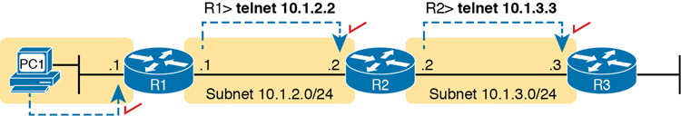
Figure 18-15 Successive Telnet Connections: PC1 to R1, R1 to R2, and R2 to R3
The Telnet connections shown in Figure 18-15 work because each Telnet in this case uses source and destination addresses in the same subnet. For example, R1’s telnet 10.1.2.2 command uses 10.1.2.2 as the destination, of course. R1 uses the outgoing interface IP address used to send packets to 10.1.2.2, 10.1.2.1 in this case. Because each of these telnet commands connects to an IP address in a connected subnet, the routing protocol could be completely misconfigured, and you could still Telnet/SSH to each successive device to troubleshoot and fix the problem.
Network engineers also use the IOS Telnet and SSH client just for preference. For instance, if you need to log in to several Cisco devices, you could open several windows and tabs on your PC, and log in from your PC (assuming the network was not having problems). Or, you could log in from your PC to some nearby Cisco router or switch, and from there Telnet or SSH to other Cisco devices.
IOS Telnet and SSH Examples
Using the IOS Telnet client via the telnet host command is pretty simple. Just use the IP address or hostname to identify the host to which you want to connect, and press Enter. Example 18-7 shows an example based on Figure 18-15, with R1 using Telnet to connect to 10.1.2.2 (R2).
Example 18-7 Telnet from R1 to R2 to View Interface Status on R2
R1# telnet 10.1.2.2
Trying 10.1.2.2 ... Open

User Access Verification

Username: wendell
Password:
R2>
R2> show ip interface brief
Interface                  IP-Address      OK? Method Status                Protocol
GigabitEthernet0/0         unassigned      YES unset  administratively down down
GigabitEthernet0/1         10.1.3.2        YES manual up                    up
GigabitEthernet0/2         10.1.2.2        YES manual up                    up
GigabitEthernet0/3         unassigned      YES unset  administratively down down
Take the time to pay close attention to the command prompts. The example begins with the user logged in to Router R1, with the R1# command prompt. After issuing the telnet 10.1.2.2 command, R2 asks the user for both a username and password because Router R2 uses local username authentication, which requires those credentials. The show ip interfaces brief command at the end of the output shows Router R2’s interfaces and IP addresses again per Example 18-7 and Figure 18-15.
The ssh -l username host command in Example 18-8 follows the same basic ideas as the telnet host command, but with an SSH client. The -l flag means that the next parameter is the login username. In this case, the user begins logged in to Router R1 and then uses the ssh -l wendell 10.1.2.2 command to SSH to Router R2. R2 expects a username/password of wendell/odom, with wendell supplied in the command and odom supplied when R2 prompts the user.
Example 18-8 SSH Client from R1 to R2 to View Interface Status on R2
R1# ssh -l wendell 10.1.2.2

Password:

R2>
Interface                  IP-Address      OK? Method Status                Protocol
GigabitEthernet0/0         unassigned      YES unset  administratively down down
GigabitEthernet0/1         10.1.3.2        YES manual up                    up
GigabitEthernet0/2         10.1.2.2        YES manual up                    up
GigabitEthernet0/3         unassigned      YES unset  administratively down down
When you have finished using the other router, you can log out from your Telnet or SSH connection using the exit or quit command.
Finally, note that IOS supports a mechanism to use hotkeys to move between multiple Telnet or SSH sessions from the CLI. Basically, starting at one router, you could telnet or SSH to a router, do some commands, and instead of using the exit command to end your connection, you could keep the connection open while still moving back to the command prompt of the original router. For instance, if starting at Router R1, you could Telnet to R2, R3, and R4, suspending but not exiting those Telnet connections. Then you could easily move between the sessions to issue new commands with a few keystrokes.
Chapter Review
One key to doing well on the exams is to perform repetitive spaced review sessions. Review this chapter’s material using either the tools in the book or interactive tools for the same material found on the book’s companion website. Refer to the “Your Study Plan” element for more details. Table 18-1 outlines the key review elements and where you can find them. To better track your study progress, record when you completed these activities in the second column.
Table 18-1 Chapter Review Tracking
Review Element |
Review Date(s) |
Resource Used |
|---|---|---|
Review key topics |
|
Book, website |
Review key terms |
|
Book, website |
Watch video |
|
Website |
Review All the Key Topics
Table 18-2 Key Topics for Chapter 18
Key Topic Element |
Description |
Page Number |
|---|---|---|
ARP tables on Layer 3 hosts, with MAC address tables on Layer 2 switch |
423 |
|
How extended ping in IOS performs a better test of the reverse route |
424 |
|
Why a standard ping over a LAN does not exercise a host’s default router logic |
425 |
|
List |
Network layer problems that could cause a ping to fail between a router and host on the same LAN subnet |
426 |
List |
Testing a host’s default router setting using extended ping |
426 |
List |
Comparisons between the ping and traceroute commands |
428 |