Chapter 21. OSPF Network Types and Neighbors
This chapter covers the following exam topics:
3.0 IP Connectivity
3.4 Configure and verify single area OSPFv2
3.4.a Neighbor adjacencies
3.4.b Point-to-point
3.4.c Broadcast (DR/BDR selection)
3.4.d Router ID
Chapter 20, “Implementing OSPF,” discussed the required and most common optional OSPF configuration settings, along with the many verification commands to show how OSPF works with those settings. This chapter continues with more OSPF implementation topics, both to round out the discussion of OSPF and to focus even more on the specific CCNA 200-301 exam topics.
The first of two major sections of this chapter focuses on OSPF network types, specifically types point-to-point and broadcast. The CCNA 200-301 exam topics mention those by name. Chapter 20 showed how OSPF operates on Ethernet interfaces when using their default network type (broadcast). This first section of the chapter discusses the meaning of OSPF network types, default settings, how to configure to use other settings, and how OSPF works differently with different settings.
The second major section then focuses on neighbors and neighbor adjacencies as mentioned in yet another of the OSPF exam topics. OSPF routers cannot exchange LSAs with another router unless they first become neighbors. This second section discusses the various OSPF features that can prevent OSPF routers from becoming neighbors and how you can go about discovering if those bad conditions exist—even if you do not have access to the running configuration.
“Do I Know This Already?” Quiz
Take the quiz (either here or use the PTP software) if you want to use the score to help you decide how much time to spend on this chapter. The letter answers are listed at the bottom of the page following the quiz. Appendix C, found both at the end of the book as well as on the companion website, includes both the answers and explanations. You can also find both answers and explanations in the PTP testing software.
Table 21-1 “Do I Know This Already?” Foundation Topics Section-to-Question Mapping
Foundation Topics Section |
Questions |
|---|---|
OSPF Network Types |
1–3 |
OSPF Neighbor Relationships |
4–6 |
1. Routers R1 and R2, with router IDs 1.1.1.1 and 2.2.2.2, connect over an Ethernet WAN link. If using all default OSPF settings, if the WAN link initializes for both routers at the same time, which of the following answers are true? (Choose two answers.)
a. Router R1 will become the DR.
b. Router R1 will dynamically discover the existence of router R2.
c. Router R2 will be neither the DR nor the BDR.
d. Router R1’s show ip ospf neighbor command will list R2 with a state of “FULL/DR.”
2. Routers R1 and R2, with router IDs 1.1.1.1 and 2.2.2.2, connect over an Ethernet WAN link. The configuration uses all defaults, except giving R1 an interface priority of 11 and changing both routers to use OSPF network type point-to-point. If the WAN link initializes for both routers at the same time, which of the following answers are true? (Choose two answers.)
a. Router R1 will become the DR.
b. Router R1 will dynamically discover the existence of router R2.
c. Router R2 will be neither the DR nor the BDR.
d. Router R2’s show ip ospf neighbor command will list R1 with a state of “FULL/DR.”
3. Per the command output, with how many routers is router R9 full adjacent over its Gi0/0 interface?
R9# show ip ospf interface brief
Interface    PID   Area            IP Address/Mask    Cost  State Nbrs F/C
Gi0/0        1     0               10.1.1.1/24        1     DROTH 2/5
a. 7
b. 0
c. 5
d. 2
4. An engineer connects routers R11 and R12 to the same Ethernet LAN and configures them to use OSPFv2. Which answers describe a combination of settings that would prevent the two routers from becoming OSPF neighbors? (Choose two answers.)
a. R11’s interface uses area 11 while R12’s interface uses area 12.
b. R11’s OSPF process uses process ID 11 while R12 uses process ID 12.
c. R11’s interface uses OSPF priority 11 while R12’s uses OSPF priority 12.
d. R11’s interface uses an OSPF Hello timer value of 11 while R12’s uses 12.
5. An engineer connects routers R13 and R14 to the same Ethernet LAN and configures them to use OSPFv2. Which answers describe a combination of settings that would prevent the two routers from becoming OSPF neighbors?
a. Both routers’ interface IP addresses reside in the same subnet.
b. Both routers’ OSPF process uses process ID 13.
c. Both routers’ OSPF process uses router ID 13.13.13.13.
d. Both routers’ interfaces use an OSPF Dead interval of 40.
6. Router R15 has been a working part of a network that uses OSPFv2. An engineer then issues the shutdown command in OSPF configuration mode on R15. Which of the following occurs?
a. R15 empties its IP routing table of all OSPF routes but keeps its LSDB intact.
b. R15 empties its LSDB but keeps OSPF neighbor relationships active.
c. R15 keeps OSPF neighbors open but does not accept new OSPF neighbors.
d. R15 keeps all OSPF configuration but ceases all OSPF activities (routes, LSDB, neighbors).
Answers to the “Do I Know This Already?” quiz:
1 B, D
2 B, C
3 D
4 A, D
5 C
6 D
Foundation Topics
OSPF Network Types
Two CCNA 200-301 exam topics might be completely misunderstood without taking a closer look at yet more default OSPF settings. In particular, the following exam topics refer to a specific per-interface OSPF setting called the network type—even listing the keywords used to configure the setting in the exam topics:
3.4.b: point-to-point
3.4.c: broadcast (DR/BDR selection)
OSPF includes a small number of network types as a setting on each OSPF-enabled interface. The setting tells the router whether or not to dynamically discover OSPF neighbors (versus requiring the static configuration of the neighboring router’s IP address) and whether or not the router should attempt to use a designated router (DR) and backup DR (BDR) in the subnet. Of the two OSPF network types included in the CCNA exam topics, both cause routers to dynamically discover neighbors, but one calls for the use of a DR while the other does not. Table 21-2 summarizes the features of the two OSPF network types mentioned in the exam topics.
Table 21-2 Two OSPF Network Types and Key Behaviors
Network Type Keyword |
Dynamically Discovers Neighbors |
Uses a DR/BDR |
|---|---|---|
broadcast |
Yes |
Yes |
point-to-point |
Yes |
No |
The rest of this first major section of the chapter explores each type.
The OSPF Broadcast Network Type
OSPF defaults to use a broadcast network type on all types of Ethernet interfaces. Note that all the Ethernet interfaces in examples in Chapter 20 relied on that default setting.
To see all the details of how the OSPF broadcast network type works, this chapter begins with a different design than the examples in Chapter 20, instead using a single area design that connects four routers to the same subnet, as shown in Figure 21-1. All links reside in area 0, making the design a single area design.
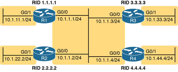
Figure 21-1 The Single Area Design Used in This Chapter
To get a sense for how OSPF operates with the broadcast network type, imagine that all four routers use a straightforward OSPF interface configuration like the router R1 configuration shown in Example 21-1. Both GigabitEthernet interfaces on all four routers default to use network type broadcast. Note that the configuration on routers R2, R3, and R4 mirrors R1’s configuration except that they use router IDs 2.2.2.2, 3.3.3.3, and 4.4.4.4, respectively, and they use the IP addresses shown in the figure.
Example 21-1 R1 OSPF Configuration to Match Figure 21-1
router ospf 1
 router-id 1.1.1.1
!
interface gigabitEthernet0/0
 ip ospf 1 area 0
!
interface gigabitEthernet0/1
 ip ospf 1 area 0
This simple design gives us a great backdrop from which to observe the results of the broadcast network type on each router. Both interfaces (G0/0 and G0/1) on each router use the broadcast network type and perform the following actions:
Attempt to discover neighbors by sending OSPF Hellos to the 224.0.0.5 multicast address (an address reserved for sending packets to all OSPF routers in the subnet)
Attempt to elect a DR and BDR on each subnet
On the interface with no other routers on the subnet (G0/1), become the DR
On the interface with three other routers on the subnet (G0/0), be either DR, BDR, or a DROther router
When sending OSPF messages to the DR or BDR, send the messages to the all-OSPF-DRs multicast address 224.0.0.6
Example 21-2 shows some of the results using the show ip ospf neighbor command. Note that R1 lists R2, R3, and R4 as neighbors (based on their 2.2.2.2, 3.3.3.3, and 4.4.4.4 router IDs), confirming that R1 dynamically discovered the other routers. Also, note that the output lists 4.4.4.4 as the DR and 3.3.3.3 as the BDR.
Example 21-2 R1’s List of Neighbors
R1# show ip ospf neighbor

Neighbor ID     Pri   State           Dead Time   Address       Interface
2.2.2.2           1   2WAY/DROTHER    00:00:35    10.1.1.2      GigabitEthernet0/0
3.3.3.3           1   FULL/BDR        00:00:33    10.1.1.3      GigabitEthernet0/0
4.4.4.4           1   FULL/DR         00:00:35    10.1.1.4      GigabitEthernet0/0
Verifying Operations with Network Type Broadcast
As discussed in the section “Using Designated Routers on Ethernet Links” in Chapter 19, “Understanding OSPF Concepts,” all discovered routers on the link should become neighbors and at least reach the 2-way state. For all neighbor relationships that include the DR and/or BDR, the neighbor relationship should further reach the full state. That section defined the term fully adjacent as a special term that refers to neighbors that reach this full state.
The design in Figure 21-1, with four routers on the same LAN, provides just enough routers so that one neighbor relationship will remain in a 2-way state and not reach the full state, as a perfectly normal way for OSPF to operate. Figure 21-2 shows the current conditions when the show commands in this chapter were gathered, with R4 as the DR, R3 as the BDR, and with R1 and R2 as DROther routers.

Figure 21-2 OSPF DR/BDR/DROther Roles in the Network
Now consider router R1’s neighbors as listed in Example 21-2. R1 has three neighbors, all reachable out its G0/0 interface. However, R1’s show ip ospf neighbor command refers to the state of R1’s relationship with the neighbor: 2-way with router 2.2.2.2. Because both R1 and R2 currently serve as DROther routers—that is, they wait ready to become the BDR if either the DR or BDR fails—their neighbor relationship remains in a 2-way state.
Examining Example 21-2 one last time, R1, as a DROther router itself, has two neighbor relationships that reach a full state: R1’s neighbor adjacency with DR R4 and R1’s neighbor adjacency with BDR R3. But R1 has a total of three neighbors, all reachable off R1’s G0/0 interface.
The idea that R1 has three neighbors off its G0/0 interface, with two being fully adjacent, is reflected on the far right of the output of the show ip ospf interface brief command output in Example 21-3. It shows “2/3,” meaning two neighbors in the full state off port G0/0, with three total neighbors on that interface. Also, note that this command’s “State” column differs from the show ip ospf neighbor commands, in that the show ip ospf interface brief command lists the local router’s role on the interface (as shown in Figure 21-2), with R1’s G0/1 acting as DR and R1’s G0/0 acting as a DROther router.
Example 21-3 Router R1 OSPF Interfaces: Local Role and Neighbor Counts
R1# show ip ospf interface brief
Interface    PID   Area            IP Address/Mask    Cost  State Nbrs F/C
Gi0/1        1     0               10.1.11.1/24       1     DR    0/0
Gi0/0        1     0               10.1.1.1/24        1     DROTH 2/3
So far, this topic has described the effect of the OSPF broadcast network type by taking advantage of the default setting on Ethernet interfaces. To see the setting, use the show ip ospf interface command, as shown in Example 21-4. The first highlighted item identifies the network type. However, this command’s output restates many of the facts seen in both the show ip ospf neighbor and show ip ospf interface brief commands in Examples 21-2 and 21-3, so take the time to browse through all of Example 21-4 and focus on the additional highlights to see those familiar items.
Example 21-4 Displaying OSPF Network Type Broadcast
R1# show ip ospf interface g0/0
GigabitEthernet0/0 is up, line protocol is up
  Internet Address 10.1.1.1/24, Area 0, Attached via Interface Enable
  Process ID 1, Router ID 1.1.1.1, Network Type BROADCAST, Cost: 1
  Topology-MTID    Cost    Disabled    Shutdown      Topology Name
        0           1         no          no            Base
  Enabled by interface config, including secondary ip addresses
  Transmit Delay is 1 sec, State DROTHER, Priority 1
  Designated Router (ID) 4.4.4.4, Interface address 10.1.1.4
  Backup Designated router (ID) 3.3.3.3, Interface address 10.1.1.3
  Timer intervals configured, Hello 10, Dead 40, Wait 40, Retransmit 5
    oob-resync timeout 40
    Hello due in 00:00:00
  Supports Link-local Signaling (LLS)
  Cisco NSF helper support enabled
  IETF NSF helper support enabled
  Index 1/1/1, flood queue length 0
  Next 0x0(0)/0x0(0)/0x0(0)
  Last flood scan length is 0, maximum is 1
  Last flood scan time is 0 msec, maximum is 0 msec
  Neighbor Count is 3, Adjacent neighbor count is 2
    Adjacent with neighbor 3.3.3.3  (Backup Designated Router)
    Adjacent with neighbor 4.4.4.4  (Designated Router)
  Suppress hello for 0 neighbor(s)
Although you would not need to configure an Ethernet interface to use the broadcast network type, some older types of interfaces over the years have used different defaults and with the option to use the broadcast network type. In those cases, the ip ospf network broadcast interface subcommand would configure the setting.
Configuring to Influence the DR/BDR Election
In some cases, you may want to influence the OSPF DR election. However, before deciding that makes sense in every case, note that OSPF DR/BDR election rules will not result in a specific router always being the DR, and another always being the BDR, assuming that each is up and working. In short, here are the rules once a DR and BDR have been elected:
If the DR fails, the BDR becomes the DR, and a new BDR is elected.
When a better router enters the subnet, no preemption of the existing DR or BDR occurs.
As a result of these rules, while you can configure a router to be the best (highest priority) router to become the DR in an election, doing so only increases that router’s statistical chances of being the DR at a given point in time. If the router fails, other routers will become DR and BDR, and the best router will not be DR again until the current DR and BDR fail.
Note
If you have begun to think about STP elections, note that the rules are similar, but with two key differences. STP uses a lowest-is-best approach and allows new switches to preempt the existing root switch to become the root. OSPF uses a highest-is-best approach and does not preempt the DR as just noted.
In some cases, you may want to influence the DR/BDR election with two configurable settings, listed here in order of precedence:

The highest OSPF interface priority: The highest value wins during an election, with values ranging from 0 to 255.
The highest OSPF Router ID: If the priority ties, the election chooses the router with the highest OSPF RID.
For example, imagine all four routers in the design shown in Figure 21-1 trying to elect the DR and BDR at the same time—for instance, after a power hit in which all four routers power off and back on again. They all participate in the election. They all tie with default priority values of 1 (see Example 21-4 for R1’s priority in the show ip ospf interface command output.) In this case, R4, with the numerically highest RID of 4.4.4.4, wins the election, and R3, with the next highest RID of 3.3.3.3, becomes the BDR.
To influence the election, you could set the various RIDs with your preferred router with the highest RID value. However, many networks choose OSPF router IDs to help identify the router easily. Instead, using the OSPF priority setting makes better sense. For instance, if an engineer preferred that R1 be the DR, the engineer could add the configuration in Example 21-5 to set R1’s interface priority to 99.
Example 21-5 Influencing DR/BDR Election Using OSPF Priority
R1# configure terminal
Configuring from terminal, memory, or network [terminal]?
Enter configuration commands, one per line.  End with CNTL/Z.
R1(config)# interface g0/0
R1(config-if)# ip ospf priority 99
R1(config-if)# ^Z
R1#
R1# show ip ospf interface g0/0 | include Priority
  Transmit Delay is 1 sec, State DROTHER, Priority 99

R1# show ip ospf neighbor
Neighbor ID     Pri   State           Dead Time   Address         Interface
2.2.2.2           1   2WAY/DROTHER    00:00:36    10.1.1.2        GigabitEthernet0/0
3.3.3.3           1   FULL/BDR        00:00:30    10.1.1.3        GigabitEthernet0/0
4.4.4.4           1   FULL/DR         00:00:37    10.1.1.4        GigabitEthernet0/0

R1# show ip ospf interface brief
Interface    PID   Area            IP Address/Mask    Cost  State Nbrs F/C
Gi0/1        1     0               10.1.11.1/24       1     DR    0/0
Gi0/0        1     0               10.1.1.1/24        1     DROTH 2/3
The configuration shows R1’s interface priority value now as 99, and the show ip ospf interface G0/0 command that follows confirms the setting. However, the last two commands in the example seem to show that the DR and BDR have not changed at all—and that output is indeed correct. In the example, note that the show ip ospf neighbor command still lists R4’s state as DR, meaning R4 still acts as the DR, while the show ip ospf interface brief command lists R1’s State (role) as DROTH.
Just to complete the process, Example 21-6 shows the results after forcing a free election (by failing the LAN switch that sits between the four routers). As expected, R1 wins and becomes DR due to its higher priority, with the other three routers tying based on priority. R4 wins between R2, R3, and R4 due to its higher RID to become the BDR.
Example 21-6 Results of a Completely New DR/BDR Election
! Not shown: LAN fails, and then recovers, causing a new OSPF Election
R1# show ip ospf neighbor

Neighbor ID     Pri   State           Dead Time   Address         Interface
2.2.2.2           1   FULL/DROTHER    00:00:37    10.1.1.2        GigabitEthernet0/0
3.3.3.3           1   FULL/DROTHER    00:00:38    10.1.1.3        GigabitEthernet0/0
4.4.4.4           1   FULL/BDR        00:00:38    10.1.1.4        GigabitEthernet0/0

R1# show ip ospf interface brief
Interface    PID   Area            IP Address/Mask    Cost  State Nbrs F/C
Gi0/1        1     0               10.1.11.1/24       1     DR    0/0
Gi0/0        1     0               10.1.1.1/24        1     DR    3/3
The OSPF Point-to-Point Network Type
The other OSPF network type mentioned in the CCNA 200-301 exam topics, point-to-point, works well for data links that by their nature have just two routers on the link. For example, consider the topology in Figure 21-3, which shows router R1 with three WAN links—two Ethernet WAN links and one serial link.
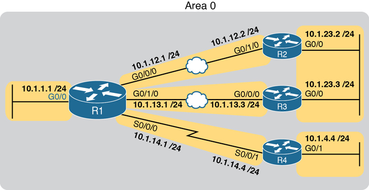
Figure 21-3 Sample OSPF Design with Serial and Ethernet WAN
First, focus on the serial link itself. To review, the jagged line represents a physical link that can at most have two devices using the link, specifically R1 and R4 in this case. The link does not support the ability to add a third router to the link. As you might guess, the data-link protocols to control a link with at most two devices can work differently than Ethernet. For instance, the data-link protocols most often used on the link (HDLC and PPP) do not support data-link broadcasts.
Next, consider the OSPF point-to-point network type: it exists for serial links and other links that use a point-to-point topology. These links often do not support data-link broadcasts. Additionally, with only two devices on the link, using a DR/BDR is not a help, and it actually adds a little extra convergence time. Using a network type of point-to-point tells the router to not use a DR/BDR on the link.
While you may see some serial links in networks today, the CCNA and CCNP Enterprise exams make no specific mention of serial technology at this point. However, you will see other point-to-point links—like some Ethernet WAN links.
To connect the thoughts, note that all the Ethernet WAN links used in this book happen to use a point-to-point Ethernet WAN service called an Ethernet Private Wire Service or simply an Ethernet Line (E-Line). For that service, the service provider will send Ethernet frames between two devices (routers) connected to the service, but only those two devices. In other words, an E-line is a point-to-point service in concept. So while the Ethernet data-link protocol supports broadcast frames, only two devices can exist on the link, and there is no advantage to using a DR/BDR. As a result, many engineers prefer to instead use an OSPF point-to-point network type on Ethernet WAN links that in effect act as a point-to-point link.
Example 21-7 shows the configuration of router R1’s G0/0/0 interface in Figure 21-3 to use OSPF network type point-to-point. R2, on the other end of the WAN link, would need the same configuration command on its matching interface.
Example 21-7 OSPF Network Type Point-to-Point on an Ethernet WAN Interface on R1
R1# configure terminal
Enter configuration commands, one per line.  End with CNTL/Z.
R1(config)# interface g0/0/0
R1(config-if)# ip ospf network point-to-point
R1(config-if)#

R1# show ip ospf interface g0/0/0
GigabitEthernet0/0/0 is up, line protocol is up
  Internet Address 10.1.12.1/24, Area 0, Attached via Interface Enable
  Process ID 1, Router ID 1.1.1.1, Network Type POINT_TO_POINT, Cost: 1
  Topology-MTID    Cost    Disabled    Shutdown      Topology Name
        0           4         no          no            Base
  Enabled by interface config, including secondary ip addresses
  Transmit Delay is 1 sec, State POINT_TO_POINT
  Timer intervals configured, Hello 10, Dead 40, Wait 40, Retransmit 5
    oob-resync timeout 40
    Hello due in 00:00:01
  Supports Link-local Signaling (LLS)
  Cisco NSF helper support enabled
  IETF NSF helper support enabled
  Index 1/3/3, flood queue length 0
  Next 0x0(0)/0x0(0)/0x0(0)
  Last flood scan length is 1, maximum is 3
  Last flood scan time is 0 msec, maximum is 0 msec
  Neighbor Count is 1, Adjacent neighbor count is 1
    Adjacent with neighbor 2.2.2.2
  Suppress hello for 0 neighbor(s)
Note the highlighted portions of the show command in Example 21-6. The first two highlights note the network type. The final highlight with two lines notes that R1 has one neighbor on the interface, a neighbor with which it has become fully adjacent per the output.
Example 21-8 closes this section with a confirmation of some of those facts with two more commands. Note that the show ip ospf neighbor command on R1 lists router R2 (RID 2.2.2.2) with a full state, but with no DR nor BDR designation, instead listing a -. The - acts as a reminder that the link does not use a DR/BDR. The second command, show ip ospf interface brief, shows the state (the local router’s role) as P2P, which is short for point-to-point, with a counter of 1 for the number of fully adjacent neighbors and total number of neighbors.
Example 21-8 OSPF Network Type Point-to-Point on an Ethernet WAN Interface on R1
R1# show ip ospf neighbor

Neighbor ID     Pri   State           Dead Time   Address       Interface
2.2.2.2           0   FULL/  -        00:00:39    10.1.12.2     GigabitEthernet0/0/0
! lines omitted for brevity

R1# show ip ospf interface brief
Interface    PID   Area            IP Address/Mask    Cost  State Nbrs F/C
Gi0/0/0      1     0               10.1.12.1/24       4     P2P   1/1
! lines omitted for brevity
When using Ethernet WAN links that behave as a point-to-point link, consider using OSPF network type point-to-point rather than using the default broadcast type.
OSPF Neighbor Relationships
A router’s OSPF configuration enables OSPF on a set of interfaces. IOS then attempts to discover other neighbors on those interfaces by sending and listening for OSPF Hello messages. However, once discovered, two routers may not become neighbors. They must have compatible values for several settings as listed in the Hellos exchanged between the two routers. This second major section of the chapter examines those reasons.
OSPF Neighbor Requirements
After an OSPF router hears a Hello from a new neighbor, the routing protocol examines the information in the Hello and compares that information with the local router’s own settings. If the settings match, great. If not, the routers do not become neighbors. Because there is no formal term for all these items that a routing protocol considers, this book just calls them neighbor requirements. Table 21-3 lists the neighbor requirements for OSPF, with some comments about the various issues following the table.
Table 21-3 Neighbor Requirements for OSPF
Requirement |
Required for OSPF |
Neighbor Missing if Incorrect |
|---|---|---|
Interfaces must be in an up/up state. |
Yes |
Yes |
Access control lists (ACL) must not filter routing protocol messages. |
Yes |
Yes |
Interfaces must be in the same subnet. |
Yes |
Yes |
They must pass routing protocol neighbor authentication (if configured). |
Yes |
Yes |
Hello and hold/dead timers must match. |
Yes |
Yes |
Router IDs (RID) must be unique. |
Yes |
Yes |
They must be in the same area. |
Yes |
Yes |
OSPF process must not be shut down. |
Yes |
Yes |
Neighboring interfaces must use same MTU setting. |
Yes |
No |
Neighboring interfaces must use same OSPF network type. |
Yes |
No |
First, consider the meaning of the two rightmost columns. The column labeled “Required for OSPF” means that the item must be working correctly for the neighbor relationship to work correctly. Note that all the items in this column list a “yes,” meaning that all must be correct for the neighbor relationship to work correctly. The last column heading states “Neighbor Missing if Incorrect.” For items listing a “yes” in this column, if that item is configured incorrectly, the neighbor will not appear in lists of OSPF neighbors—for instance, with the show ip ospf neighbor command.
Next, focus on the shaded items at the top of the table. The symptom that occurs if either of these is a problem is that the show ip ospf neighbor command would not list the other router. For instance, the first item states that the router interfaces must be up and working. If the router interface is not working, the router cannot send any OSPF messages and discover any OSPF neighbors on that interface.
The middle section of the table (the unshaded rows) focuses on some OSPF settings. These items must be correct, but if not, they also result in the neighbor not being listed in the output of the show ip ospf neighbor command.
As you can see, using the show ip ospf neighbor command can give you a good starting point to troubleshoot OSPF on the exam and in real life. If you see the neighbor you expect to see, great! If not, the table gives you a good list to use for items to investigate.
Finally, the last section (shaded) lists a couple of OSPF settings that give a different symptom when incorrect. Again, those two items must be correct for OSPF neighbors to work. However, for these two items, when incorrect, a router can list the other router as a neighbor, but the neighbor relationship does not work properly in that the routers do not exchange LSAs as they should.
For reference, Table 21-4 relists some of the requirements from Table 21-3, along with the most useful commands with which to find the answers.
Table 21-4 OSPF Neighbor Requirements and the Best show/debug Commands
Requirement |
Best show Command |
|---|---|
Hello and dead timers must match. |
show ip ospf interface |
They must be in the same area. |
show ip ospf interface brief |
RIDs must be unique. |
show ip ospf |
They must pass any neighbor authentication. |
show ip ospf interface |
OSPF process must not be shut down. |
show ip ospf, show ip ospf interface |
The rest of this section looks at some of the items from Table 21-3 in a little more detail.
Note
One configuration choice that people sometimes think is an issue, but is not, is the process ID as defined by the router ospf process-id command. Neighboring routers can use the same process ID values, or different process ID values, with no impact on whether two routers become OSPF neighbors.
Issues That Prevent Neighbor Adjacencies
The next few pages look at three of the topics from Table 21-3 for which, if a problem exists, the router does not become a neighbor (that is, the unshaded parts of the table.). To show the issues, this section uses the same topology shown earlier in Figure 21-1 but now with some incorrect configuration introduced. In other words, the configuration matches Example 21-1 that began this chapter, but with the following errors introduced:
R2 has been configured with both LAN interfaces in area 1, whereas the other three routers’ G0/0 interfaces are assigned to area 0.
R3 is using the same RID (1.1.1.1) as R1.
R4 has been configured with a Hello/dead timer of 5/20 on its G0/0 interface, instead of the 10/40 used (by default) on R1, R2, and R3.
Figure 21-4 shows these same problems for reference.

Figure 21-4 Summary of Problems That Prevent OSPF Neighbors on the Central LAN
Finding Area Mismatches
To create an area mismatch, the configuration on some router must place the interface into the wrong area per the design. As shown in Figure 21-4, router R2 was configured incorrectly, placing both its interfaces into area 1 instead of area 0. Example 21-9 shows the configuration, which uses the correct syntax (and is therefore accepted by the router) but sets the wrong area number.
Example 21-9 Setting Area 1 on R2’s Interfaces, When They Should Be in Area 0
router ospf 1
 router-id 2.2.2.2
!
interface gigabitEthernet0/0
 ip ospf 1 area 1
!
interface gigabitEthernet0/1
 ip ospf 1 area 1
With an area mismatch error, the show ip ospf neighbor command will not list the neighbor. Because you see nothing in the OSPF neighbor table, to troubleshoot this problem, you need to find the area configuration on each interface on potentially neighboring routers. To do so:
Check the output of show running-config to look for
ip ospf process-id area area-number interface subcommands
network commands in OSPF configuration mode
Use the show ip ospf interface [brief] command to list the area number
Finding Duplicate OSPF Router IDs
Next, Example 21-10 shows R1 and R3 both trying to use RID 1.1.1.1. Interestingly, both routers automatically generate a log message for the duplicate OSPF RID problem between R1 and R3; the end of Example 21-10 shows one such message. For the exams, just use the show ip ospf commands on both R3 and R1 to easily list the RID on each router, noting that they both use the same value.
Example 21-10 Comparing OSPF Router IDs on R1 and R3
! Next, on R3: R3 lists the RID of 1.1.1.1
!
R3# show ip ospf
Routing Process "ospf 1" with ID 1.1.1.1
Start time: 00:00:37.136, Time elapsed: 02:20:37.200
! lines omitted for brevity
! Back to R1: R1 also uses RID 1.1.1.1
R1# show ip ospf
Routing Process "ospf 1" with ID 1.1.1.1
Start time: 00:01:51.864, Time elapsed: 12:13:50.904
! lines omitted for brevity

*May 29 00:01:25.679: %OSPF-4-DUP_RTRID_NBR: OSPF detected duplicate router-id
1.1.1.1 from 10.1.1.3 on interface GigabitEthernet0/0
First, focus on the problem: the duplicate RIDs. The first line of the show ip ospf command on the two routers quickly shows the duplicate use of 1.1.1.1. To solve the problem, assuming R1 should use 1.1.1.1 and R3 should use another RID (maybe 3.3.3.3), change the RID on R3 and restart the OSPF process. To do so, use the router-id 3.3.3.3 OSPF subcommand and use the EXEC mode command clear ip ospf process. (OSPF will not begin using a new RID value until the process restarts, either via command or reload.)
Finding OSPF Hello and Dead Timer Mismatches
First, as a reminder from chapters past:
Hello interval/timer: The per-interface timer that tells a router how often to send OSPF Hello messages on an interface.
Dead interval/timer: The per-interface timer that tells the router how long to wait without having received a Hello from a neighbor before believing that neighbor has failed. (Defaults to four times the Hello timer.)
Next, consider the problem created on R4, with the configuration of a different Hello timer and dead timer (5 and 20, respectively) as compared with the default settings on R1, R2, and R3 (10 and 40, respectively). A Hello or Dead interval mismatch prevents R4 from becoming neighbors with any of the other three OSPF routers. Routers list their Hello and Dead interval settings in their Hello messages and choose to not become neighbors if the values do not match. As a result, none of the routers become neighbors with router R4 in this case.
Example 21-11 shows the easiest way to find the mismatch using the show ip ospf interface command on both R1 and R4. This command lists the Hello and dead timers for each interface, as highlighted in the example. Note that R1 uses 10 and 40 (Hello and dead), whereas R4 uses 5 and 20.
Example 21-11 Finding Mismatched Hello/Dead Timers
R1# show ip ospf interface G0/0
GigabitEthernet0/0 is up, line protocol is up
  Internet Address 10.1.1.1/24, Area 0, Attached via Network Statement
  Process ID 1, Router ID 1.1.1.1, Network Type BROADCAST, Cost: 1
  Topology-MTID  Cost  Disabled  Shutdown   Topology Name
        0         1       no        no         Base
  Transmit Delay is 1 sec, State DR, Priority 1
  Designated Router (ID) 1.1.1.1, Interface address 10.1.1.1
  No backup designated router on this network
  Timer intervals configured, Hello 10, Dead 40, Wait 40, Retransmit 5
! lines omitted for brevity
! Moving on to R4 next
!
R4# show ip ospf interface Gi0/0
GigabitEthernet0/0 is up, line protocol is up
   Internet Address 10.1.1.4/24, Area 0, Attached via Network Statement
   Process ID 4, Router ID 10.1.44.4, Network Type BROADCAST, Cost: 1
  Topology-MTID  Cost  Disabled  Shutdown   Topology Name
        0         1       no        no         Base
  Transmit Delay is 1 sec, State DR, Priority 1
  Transmit Delay is 1 sec, State DR, Priority 1
  Designated Router (ID) 10.1.44.4, Interface address 10.1.1.4
  No backup designated router on this network
  Timer intervals configured, Hello 5, Dead 20, Wait 20, Retransmit 5
! lines omitted for brevity
Shutting Down the OSPF Process
Similar to administratively disabling and enabling an interface, IOS also allows the OSPFv2 routing protocol process to be disabled and enabled with the shutdown and no shutdown router mode subcommands, respectively. When a routing protocol process is shut down, IOS does the following:
Brings down all neighbor relationships and clears the OSPF neighbor table
Clears the LSDB
Clears the IP routing table of any OSPF-learned routes
At the same time, shutting down OSPF does retain some important details about OSPF, in particular:
IOS retains all OSPF configuration.
IOS still lists all OSPF-enabled interfaces in the OSPF interface list (show ip ospf interface) but in a DOWN state.
Basically, shutting down the OSPF routing protocol process gives the network engineer a way to stop using the routing protocol on that router without having to remove all the configuration. Once shut down, the show ip ospf interface [brief] command should still list some output, as will the show ip ospf command, but the rest of the commands will list nothing.
Example 21-12 shows an example on Router R5, as shown in Figure 21-5. R5 is a different router than the one used in earlier examples, but it begins the example with two OSPF neighbors, R2 and R3, with router IDs 2.2.2.2 and 3.3.3.3. The example shows the OSPF process being shut down, the neighbors failing, and those two key OSPF show commands: show ip ospf neighbor and show ip ospf interface brief.

Figure 21-5 Example Network to Demonstrate OSPF Process Shutdown
Example 21-12 Shutting Down an OSPF Process, and the Resulting Neighbor States
R5# show ip ospf neighbor
Neighbor ID    Pri   State        Dead Time    Address         Interface
2.2.2.2          1   FULL/DR      00:00:35     10.1.12.2       GigabitEthernet0/1
3.3.3.3          1   FULL/DR      00:00:33     10.1.13.3       GigabitEthernet0/2
R5# configure terminal
Enter configuration commands, one per line. End with CNTL/Z.
R5(config)# router ospf 1
R5(config-router)# shutdown
R5(config-router)# ^Z
*Mar 23 12:43:30.634: %OSPF-5-ADJCHG: Process 1, Nbr 2.2.2.2 on GigabitEthernet0/1
  from FULL to DOWN, Neighbor Down: Interface down or detached
*Mar 23 12:43:30.635: %OSPF-5-ADJCHG: Process 1, Nbr 3.3.3.3 on GigabitEthernet0/2
  from FULL to DOWN, Neighbor Down: Interface down or detached
R5# show ip ospf interface brief
Interface    PID    Area        IP Address/Mask   Cost  State Nbrs F/C
Gi0/1        1      0           10.1.12.1/24      1     DOWN  0/0
Gi0/2        1      0           10.1.13.1/24      1     DOWN  0/0

R5# show ip ospf
 Routing Process "ospf 1" with ID 5.5.5.5
 Start time: 5d23h, Time elapsed: 1d04h
 Routing Process is shutdown
! lines omitted for brevity

R5# show ip ospf neighbor
R5#
R5# show ip ospf database
            OSPF Router with ID (3.3.3.3) (Process ID 1)
R5#
First, before the shutdown, the show ip ospf neighbor command lists two neighbors. After the shutdown, the same command lists no neighbors at all. Second, the show ip ospf interface brief command does list the interfaces on which OSPF is enabled, on the local router’s own IP addresses. However, it lists a state of DOWN, which is a reference to the local router’s state. Also, note that the show ip ospf command positively states that the OSPF process is in a shutdown state, while the show ip ospf database command output lists only a heading line, with no LSAs.
Issues That Allow Adjacencies but Prevent IP Routes
The last two issues to discuss in this section have a symptom in which the show ip ospf neighbor command does list a neighbor, but some other problem exists that prevents the eventual addition of OSPF routes to the routing table. The two issues: a mismatched MTU setting and a mismatched OSPF network type.
Mismatched MTU Settings
The MTU size defines a per-interface setting used by the router for its Layer 3 forwarding logic, defining the largest network layer packet that the router will forward out each interface. For instance, the IPv4 MTU size of an interface defines the maximum size IPv4 packet that the router can forward out an interface.
Routers often use a default MTU size of 1500 bytes, with the ability to set the value as well. The ip mtu size interface subcommand defines the IPv4 MTU setting, and the ipv6 mtu size command sets the equivalent for IPv6 packets.
In an odd twist, two OSPFv2 routers can actually become OSPF neighbors, be listed in the output of the show ip ospf neighbor command, and reach 2-way state, even if they happen to use different IPv4 MTU settings on their interfaces. However, they fail to exchange their LSDBs. Eventually, after trying and failing to exchange their LSDBs, the neighbor relationship also fails. So also keep a watch for MTU mismatches, although they may be unusual and obscure, by looking at the running-config and by using the show interfaces command (which lists the IP MTU).
Mismatched OSPF Network Types
Earlier in this chapter you read about the OSPF broadcast network type, which uses a DR/BDR, and the OSPF point-to-point network type, which does not. Interestingly, if you misconfigure network type settings such that one router uses broadcast, and the other uses point-to-point, the following occurs:
The two routers become fully adjacent neighbors (that is, they reach a full state).
They exchange their LSDBs.
They do not add IP routes to the IP routing table.
The reason for not adding the routes has to do with the details of LSAs and how the use of a DR (or not) changes those LSAs. Basically, the two routers expect different details in the LSAs, and the SPF algorithm notices those differences and cannot trust the LSAs because of those differences.
For instance, earlier in Example 21-7, the configuration showed router R1 using network type point-to-point on its G0/0/0 interface, with the expectation that router R2 would also use point-to-point on its matching G0/1/0 interface. Example 21-13 shows some of the results if the engineer neglected to configure R2, leaving it with the default setting of broadcast.
Example 21-13 Shutting Down an OSPF Process, and the Resulting Neighbor States
*Apr 10 16:31:01.951: %OSPF-4-NET_TYPE_MISMATCH: Received Hello from 2.2.2.2 on
  GigabitEthernet0/0/0 indicating a potential network type mismatch
R1# show ip ospf neighbor

Neighbor ID     Pri   State           Dead Time   Address       Interface
2.2.2.2           0   FULL/  -        00:00:38    10.1.12.2     GigabitEthernet0/0/0
R1#
R2# show ip ospf neighbor

Neighbor ID     Pri   State           Dead Time   Address       Interface
1.1.1.1           1   FULL/BDR        00:00:30    10.1.12.1     GigabitEthernet0/1/0
As you can see, both routers list the other as an OSPF neighbor in the full state. However, R1, with network type point-to-point, does not list a DR or BDR role in the output, while R2 does, which is one clue for this type of problem. The other comes with noticing that the expected routes are not in the IP routing table.
Chapter Review
One key to doing well on the exams is to perform repetitive spaced review sessions. Review this chapter’s material using either the tools in the book or interactive tools for the same material found on the book’s companion website. Refer to the “Your Study Plan” element for more details. Table 21-5 outlines the key review elements and where you can find them. To better track your study progress, record when you completed these activities in the second column.
Table 21-5 Chapter Review Tracking
Review Element |
Review Date(s) |
Resource Used: |
|---|---|---|
Review key topics |
|
Book, website |
Review command tables |
|
Book |
Review memory tables |
|
Website |
Watch video |
|
Website |
Review All the Key Topics
Table 21-6 Key Topics for Chapter 21
Key Topic Element |
Description |
Page Number |
|---|---|---|
Two OSPF Network Types and Key Behaviors |
501 |
|
OSPF interfaces, local roles, and neighbor counts |
503 |
|
List |
Rules for electing an OSPF DR/BDR |
505 |
Evidences of OSPF network type point-to-point |
508 |
|
Neighbor requirements for OSPF |
509 |
|
Useful commands to discover OSPF neighbor issues |
510 |
|
List |
Symptoms of an OSPF network type mismatch |
515 |
Command References
Tables 21-7 and 21-8 list configuration and verification commands used in this chapter. As an easy review exercise, cover the left column in a table, read the right column, and try to recall the command without looking. Then repeat the exercise, covering the right column, and try to recall what the command does.
Table 21-7 Chapter 21 Configuration Command Reference
Command |
Description |
|---|---|
ip ospf hello-interval seconds |
Interface subcommand that sets the interval for periodic Hellos |
ip ospf dead-interval number |
Interface subcommand that sets the OSPF dead timer |
passive-interface type number |
Router subcommand, for both OSPF and EIGRP, that tells the routing protocol to stop sending Hellos and stop trying to discover neighbors on that interface |
ip ospf priority value |
Interface subcommand that sets the OSPF priority, used when electing a new DR or BDR |
ip ospf network {broadcast | point-to-point} |
Interface subcommand used to set the OSPF network type on the interface |
[no] shutdown |
An OSPF configuration mode command to disable (shutdown) or enable (no shutdown) the OSPF process |
Table 21-8 Chapter 21 show Command Reference
Command |
Description |
|---|---|
show ip protocols |
Shows routing protocol parameters and current timer values, including an effective copy of the routing protocols’ network commands and a list of passive interfaces |
show ip ospf interface brief |
Lists the interfaces on which the OSPF protocol is enabled (based on the network commands), including passive interfaces |
show ip ospf interface [type number] |
Lists detailed OSPF settings for all interfaces, or the listed interface, including Hello and dead timers and OSPF area |
show ip ospf neighbor |
Lists neighbors and current status with neighbors, per interface |
show ip ospf |
Lists a group of messages about the OSPF process itself, listing the OSPF Router ID in the first line |
show interfaces |
Lists a long set of messages, per interface, that lists configuration, state, and counter information |