Chapter 15. Operating Cisco Routers
This chapter covers the following exam topics:
1.0 Network Fundamentals
1.1 Explain the role and function of network components
1.1.a Routers
1.2 Describe characteristics of network topology architectures
1.2.e Small office/home office (SOHO)
1.6 Configure and verify IPv4 addressing and subnetting
Getting an IPv4 network up and working requires some basic steps: installing routers, installing cables, and ordering WAN services. The installation also requires some router configuration because routers often use defaults so that the router does not route IP packets until configuration has been added. You will need to configure IPv4 addresses, enable interfaces, and add IP routes—either through static configuration or by enabling some dynamic routing protocol. This chapter focuses on the first steps to creating a small working network: how to install an enterprise-class Cisco router and configure interfaces and IP addresses.
This chapter breaks the topics into two major headings. The first discusses the physical installation of an enterprise-class Cisco router. The second section looks at the command-line interface (CLI) on a Cisco router, which has the same look and feel as the Cisco switch CLI. This section first lists the similarities between a switch and router CLI and then introduces the configuration required to make the router start forwarding IP packets on its interfaces.
“Do I Know This Already?” Quiz
Take the quiz (either here or use the PTP software) if you want to use the score to help you decide how much time to spend on this chapter. The letter answers are listed at the bottom of the page following the quiz. Appendix C, found both at the end of the book as well as on the companion website, includes both the answers and explanations. You can also find both answers and explanations in the PTP testing software.
Table 15-1 “Do I Know This Already?” Foundation Topics Section-to-Question Mapping
Foundation Topics Section |
Questions |
|---|---|
Installing Cisco Routers |
1 |
Enabling IPv4 Support on Cisco Routers |
2–6 |
1. Which of the following installation steps are more likely required on a Cisco router, but not typically required on a Cisco switch? (Choose two answers.)
a. Connect Ethernet cables
b. Connect serial cables
c. Connect to the console port
d. Connect the power cable
e. Turn the on/off switch to “on”
2. Which of the following commands might you see associated with a router CLI, but not with a switch CLI?
a. The show mac address-table command
b. The show ip route command
c. The show running-config command
d. The show interfaces status command
3. Which answers list a task that could be helpful in making a router interface G0/0 ready to route packets? (Choose two answers.)
a. Configuring the ip address address mask command in G0/0 configuration mode
b. Configuring the ip address address and ip mask mask commands in G0/0 configuration mode
c. Configuring the no shutdown command in G0/0 configuration mode
d. Setting the interface description in G0/0 configuration mode
4. The output of the show ip interface brief command on R1 lists interface status codes of “down” and “down” for interface GigabitEthernet 0/0. The interface connects to a LAN switch with a UTP straight-through cable. Which of the following could be true?
a. The shutdown command is currently configured for router interface G0/0.
b. The shutdown command is currently configured for the switch interface on the other end of the cable.
c. The router was never configured with an ip address command on the interface.
d. The router was configured with the no ip address command.
5. Which of the following commands do not list the IP address and mask of at least one interface? (Choose two answers.)
a. show running-config
b. show protocols type number
c. show ip interface brief
d. show interfaces
e. show version
6. Which of the following is different on the Cisco switch CLI for a Layer 2 switch as compared with the Cisco router CLI?
a. The commands used to configure simple password checking for the console
b. The number of IP addresses configured
c. The configuration of the device’s hostname
d. The configuration of an interface description
Answers to the “Do I Know This Already?” quiz:
1 B, E
2 B
3 A, C
4 C
5 C, E
6 B
Foundation Topics
Installing Cisco Routers
Routers collectively provide the main feature of the network layer—the capability to forward packets end to end through a network. As introduced in Chapter 3, “Fundamentals of WANs and IP Routing,” routers forward packets by connecting to various physical network links, like Ethernet LAN, Ethernet WAN, and serial WAN links, then using Layer 3 routing logic to choose where to forward each packet. As a reminder, Chapter 2, “Fundamentals of Ethernet LANs,” covered the details of making those physical connections to Ethernet networks, while Chapter 3 covered the basics of cabling with WAN links.
This section examines some of the details of router installation and cabling, first from the enterprise perspective and then from the perspective of connecting a typical small office/home office (SOHO) to an ISP using high-speed Internet.
Installing Enterprise Routers
A typical enterprise network has a few centralized sites as well as lots of smaller remote sites. To support devices at each site (the computers, IP phones, printers, and other devices), the network includes at least one LAN switch at each site. In addition, each site has a router, which connects to the LAN switch and to some WAN link. The WAN link provides connectivity from each remote site, back to the central site, and to other sites through the connection to the central site.
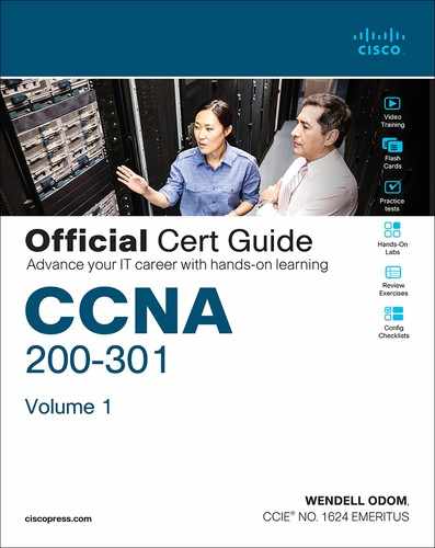
Figures 15-1 and 15-2 show a couple of different kinds of network diagrams that might be used to represent an enterprise network. The style of Figure 15-1 supports discussions about Layer 3 topics, showing the subnet IDs, masks, and interface IP addresses in shorthand. The figure also keeps the physical and data-link details to a minimum with these conventions:
Ethernet LAN: Simple straight lines with one or more LAN switches implied but not shown.
Ethernet WAN: Shown as a straight line, often with a cloud over it, with some kind of Ethernet interface identifier shown by the router (in this case, G0/1/0 and G0/0/0, which refers to GigabitEthernet interfaces).
Serial WAN: A line with a crooked part in the middle (a “lightning bolt”) represents a typical point-to-point serial link as introduced in Chapter 3.
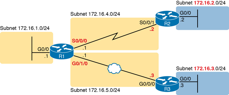
Figure 15-1 Generic Enterprise Network Diagram
In comparison, Figure 15-2 shows more detail about the physical cabling with less detail about the IP subnets and addresses. First, if the diagram needs to show physical details in the LAN, the diagram could show the LAN switches and related devices to the outside of the figure. The router Ethernet interfaces have an RJ-45 connector; just connect the appropriate UTP cable to both the router and the nearby LAN switch.
Figure 15-2 More Detailed Cabling Diagram for the Same Enterprise Network
Next, consider the hardware on the ends of the serial link, in particular where the channel service unit/data service unit (CSU/DSU) hardware resides on each end of the serial link. In a real serial link that runs through a service provider, the link terminates at a CSU/DSU. The CSU/DSU can either sit outside the router as a separate device (as shown on the left at router R1) or integrated into the router’s serial interface hardware (as shown on the right).
As for cabling, the service provider will run the cable into the enterprise’s wiring closet and often put an RJ-48 connector (same size as an RJ-45 connector) on the end of the cable. That cable should connect to the CSU/DSU. With an internal CSU/DSU (as with router R1 in Figure 15-2), the router serial port has an RJ-48 port to which the serial cable should connect. With an external CSU/DSU, the CSU/DSU must be connected to the router’s serial card via a short serial cable.
Cisco Integrated Services Routers
Product vendors, including Cisco, typically provide several different types of router hardware. Today, routers often do much more work than simply routing packets; in fact, they serve as a device or platform from which to provide many network services. Cisco even brands its enterprise routers not just as routers, but as “integrated services routers,” emphasizing the multipurpose nature of the products.
As an example, consider the networking functions needed at a typical branch office. A typical enterprise branch office needs a router for WAN/LAN connectivity, and a LAN switch to provide a high-performance local network and connectivity into the router and WAN. Many branches also need voice-over-IP (VoIP) services to support IP phones, and several security services as well. Plus, it is hard to imagine a site with users that does not have Wi-Fi access today. So, rather than require multiple separate devices at one site, as shown in Figure 15-2, Cisco offers single devices that act as both router and switch and provide other functions as well.
For the sake of learning and understanding the different functions, this book focuses on using a separate switch and separate router, which provides a much cleaner path for learning the basics.
Figure 15-3 shows a photo of the Cisco 4321 ISR, with some of the more important features highlighted. The top part of the figure shows a full view of the back of the router. This model comes with two built-in Gigabit Ethernet interfaces and two modular slots that allow you to add small cards called Network Interface Modules (NIMs). The bottom of the figure shows one example NIM (a NIM that provides two serial interfaces). The router has other items as well, including both an RJ-45 and USB console port.

Figure 15-3 Photos of a Model 4321 Cisco Integrated Services Router (ISR)
The figure shows an important feature for using routers to connect to both Ethernet LANs and Ethernet WAN services. Look closely at Figure 15-3’s Gigabit interfaces. Gi0/1 refers to interface GigabitEthernet0/1 and is an RJ-45 port that supports UTP cabling only. However, interface Gi0/0 (short for GigabitEthernet0/0) has some interesting features:
The router has two ports for one interface (Gi0/0).
You can use one or the other at any point in time, but not both.
One physical port is an RJ-45 port that supports copper cabling (implying that it is used to connect to a LAN).
The other Gi0/0 physical port is a Small Form Pluggable (SFP) port that would support various fiber Ethernet standards, allowing the port to be used for Ethernet WAN purposes.
Cisco commonly makes one or more of the Ethernet ports on its Enterprise class routers support SFPs so that the engineer can choose an SFP that supports the type of Ethernet cabling provided by the Ethernet WAN service provider.
Note
When building a lab network to study for CCNA or CCNP, because your devices will be in the same place, you can create Ethernet WAN links by using the RJ-45 ports and a UTP cable without the need to purchase an SFP for each router.
Physical Installation
Armed with the cabling details in images like Figure 15-2 and the router hardware details in photos like Figure 15-3, you can physically install a router. To install a router, follow these steps:
Step 1. For any Ethernet LAN interface, connect the RJ-45 connector of an appropriate copper Ethernet cable between the RJ-45 Ethernet port on the router and one of the LAN switch ports.
Step 2. For any serial WAN ports:
A. If using an external CSU/DSU, connect the router’s serial interface to the CSU/DSU and the CSU/DSU to the line from the telco.
B. If using an internal CSU/DSU, connect the router’s serial interface to the line from the telco.
Step 3. For any Ethernet WAN ports:
A. When ordering the Ethernet WAN service, confirm the required Ethernet standard and SFP type required to connect to the link, and order the SFPs.
B. Install the SFPs into the routers, and connect the Ethernet cable for the Ethernet WAN link to the SFP on each end of the link.
Step 4. Connect the router’s console port to a PC (as discussed in Chapter 4, “Using the Command-Line Interface”), as needed, to configure the router.
Step 5. Connect a power cable from a power outlet to the power port on the router.
Step 6. Power on the router.
Note that Cisco enterprise routers typically have an on/off switch, while switches do not.
Installing SOHO Routers
The terms enterprise router and small office/home office (SOHO) router act as a pair of contrasting categories for routers, both in terms of how vendors like Cisco provide to the market, and how enterprises use and configure those devices. The term enterprise router typically refers to a router that a company would use in a permanent business location, while a SOHO router would reside at an employee’s home or at a small permanent site with just a few people. However, as you might guess, the line between a router acting as an enterprise router and a SOHO router is blurry, so use these terms as general categories.
Even with that general comparison, SOHO routers typically have two features that an enterprise router would be less likely to have:
SOHO routers almost always use the Internet and virtual private network (VPN) technology for their WAN connections to send data back and forth to the rest of the Enterprise.
SOHO routers almost always use a multifunction device that does routing, LAN switching, VPN, wireless, and maybe other features.
For instance, at an enterprise business location, the building may contain enterprise routers, separate Ethernet switches, and separate wireless access points (AP), all connected together. At a permanent business site with four employees and 10 total devices in the network, one SOHO router could provide all those same features in one device.
For instance, Figure 15-4 shows a typical SOHO site. The three icons that represent a router, switch, and access point actually all exist inside one box; the figure just shows them separately to emphasize the fact that the one SOHO router provides several functions. On the left, the SOHO router provides wired and wireless LAN servers, and on the right, it provides WAN access through a cable Internet connection.

Figure 15-4 Devices in a SOHO Network with High-Speed CATV Internet
Figure 15-4 does not reflect the physical reality of a SOHO router, so Figure 15-5 shows one cabling example. The figure shows user devices on the left, connecting to the router via wireless or via Ethernet UTP cabling. On the right in this case, the router uses an external cable modem to connect to the coaxial cable provided by the ISP. Then the router must use a normal UTP Ethernet port to connect a short Ethernet cable between the SOHO router and the cable modem.

Figure 15-5 SOHO Network, Using Cable Internet and an Integrated Device
Enabling IPv4 Support on Cisco Router Interfaces
Routers support a relatively large number of features, with a large number of configuration and EXEC commands to support those features. You will learn about many of these features throughout the rest of this book.
Note
For perspective, the Cisco router documentation includes a command reference, with an index to every single router command. A quick informal count of a recent IOS version listed around 5000 CLI commands.
This second section of the chapter focuses on commands related to router interfaces. To make routers work—that is, to route IPv4 packets—the interfaces must be configured. This section introduces the most common commands that configure interfaces, make them work, and give the interfaces IP addresses and masks.
Accessing the Router CLI
Accessing a router’s command-line interface (CLI) works much like a switch. In fact, it works so much like accessing a Cisco switch CLI that this book relies on Chapter 4 instead of repeating the same details here. If the details from Chapter 4 are not fresh in your memory, it might be worthwhile to spend a few minutes briefly reviewing that chapter as well as Chapter 7, “Configuring and Verifying Switch Interfaces,” before reading further.
Cisco switches and routers share many of the same CLI navigation features and many of the same configuration commands for management features. The following list mentions the highlights:

User and Enable (privileged) mode
Entering and exiting configuration mode, using the configure terminal, end, and exit commands and the Ctrl+Z key sequence
Configuration of console, Telnet (vty), and enable secret passwords
Configuration of Secure Shell (SSH) encryption keys and username/password login credentials
Configuration of the hostname and interface description
Configuration of Ethernet interfaces that can negotiate speed using the speed and duplex commands
Configuration of an interface to be administratively disabled (shutdown) and administratively enabled (no shutdown)
Navigation through different configuration mode contexts using commands like line console 0 and interface type number
CLI help, command editing, and command recall features
The meaning and use of the startup-config (in NVRAM), running-config (in RAM), and external servers (like TFTP), along with how to use the copy command to copy the configuration files and IOS images
At first glance, this list seems to cover most everything you have read so far in this book about the switch CLI. However, a couple of topics do work differently with the router CLI as compared to the switch CLI, as follows:
The configuration of IP addresses differs in some ways, with switches using a VLAN interface and routers using an IP address configured on each working interface.
Many Cisco router models have an auxiliary (Aux) port, intended to be connected to an external modem and phone line to allow remote users to dial in to the router, and access the CLI, by making a phone call. Cisco switches do not have auxiliary ports.
Router IOS defaults to disallow both Telnet and SSH into the router because of the typical router default setting of transport input none in vty configuration mode. (Cisco Catalyst LAN switches typically default to allow both Telnet and SSH.) Chapter 6, “Configuring Basic Switch Management,” already discussed the various options on this command to enable Telnet (transport input telnet), SSH (transport input ssh), or both (transport input all or transport input telnet ssh).
The router CLI also differs from a switch CLI just because switches and routers do different things. For example:
Cisco Layer 2 switches support the show mac address-table command, while Cisco routers do not.
Cisco routers support the show ip route command, while Cisco Layer 2 switches do not.
Cisco Layer 2 switches use the show interfaces status command to list one line of output per interface (and routers do not), while routers use the show ip interface brief command to list similar information (but switches do not).
Note also that some Cisco devices perform both Layer 2 switching and Layer 3 routing, and those devices support both router and switch commands. Chapter 17, “IP Routing in the LAN,” discusses one such device, a Layer 3 switch, in more detail.
Router Interfaces
One minor difference between Cisco switches and routers is that routers support a much wider variety of interfaces. Today, LAN switches support Ethernet LAN interfaces of various speeds. Routers support a variety of other types of interfaces, including serial interfaces, cable TV, DSL, 3G/4G wireless, and others not mentioned in this book.
Most Cisco routers have at least one Ethernet interface of some type. Many of those Ethernet interfaces support multiple speeds and use autonegotiation, so for consistency, the router IOS refers to these interfaces based on the fastest speed. For example, a 10-Mbps-only Ethernet interface would be configured with the interface ethernet number configuration command, a 10/100 interface with the interface fastethernet number command, and a 10/100/1000 interface with the interface gigabitethernet number command. However, when discussing these interfaces all together, engineers would simply call them ethernet interfaces, regardless of the maximum speed.
Some Cisco routers have serial interfaces. As you might recall from Chapter 3, Cisco routers use serial interfaces to connect to a serial link. Each point-to-point serial link can then use High-Level Data Link Control (HDLC, the default) or Point-to-Point Protocol (PPP).
Routers refer to interfaces in many commands, first by the type of interface (Ethernet, Fast Ethernet, Gigabit Ethernet, Serial, and so on) and then with a unique number of that router. Depending on the router model, the interface numbers might be a single number, two numbers separated by a slash, or three numbers separated by slashes. For example, all three of the following configuration commands are correct on at least one model of Cisco router:
interface ethernet 0
interface fastethernet 0/1
interface gigabitethernet 0/0
interface gigabitethernet 0/1/0
interface serial 1/0/1
Two of the most common commands to display the interfaces, and their status, are the show ip interface brief and show interfaces commands. The first of these commands displays a list with one line per interface, with some basic information, including the interface IP address and interface status. The second command lists the interfaces, but with a large amount of information per interface. Example 15-1 shows a sample of each command. The output comes from a 2900-series ISR router, used in many examples in this book; note that it has both a Gi0/0 interface and a Gi0/1/0 interface, showing a case with both two-digit and three-digit interface identifiers.
Example 15-1 Listing the Interfaces in a Router
R1# show ip interface brief
Interface                  IP-Address      OK? Method Status                Protocol
Embedded-Service-Engine0/0 unassigned      YES NVRAM  administratively down down
GigabitEthernet0/0         172.16.1.1      YES NVRAM  up                    up
GigabitEthernet0/1         unassigned      YES NVRAM  administratively down down
Serial0/0/0                172.16.4.1      YES manual up                    up
Serial0/0/1                unassigned      YES unset  administratively down down
GigabitEthernet0/1/0       172.16.5.1      YES NVRAM  up                    up

R1# show interfaces gigabitEthernet 0/1/0
GigabitEthernet0/1/0 is up, line protocol is up
  Hardware is EHWIC-1GE-SFP-CU, address is 0201.a010.0001 (bia 30f7.0d29.8570)
  Description: Link in lab to R3's G0/0/0
  Internet address is 172.16.5.1/24
  MTU 1500 bytes, BW 1000000 Kbit/sec, DLY 10 usec,
     reliability 255/255, txload 1/255, rxload 1/255
  Encapsulation ARPA, loopback not set
  Keepalive set (10 sec)
  Full Duplex, 1Gbps, media type is RJ45
  output flow-control is XON, input flow-control is XON
  ARP type: ARPA, ARP Timeout 04:00:00
  Last input 00:00:29, output 00:00:08, output hang never
  Last clearing of "show interface" counters never
  Input queue: 0/75/0/0 (size/max/drops/flushes); Total output drops: 0
  Queueing strategy: fifo
  Output queue: 0/40 (size/max)
  5 minute input rate 0 bits/sec, 0 packets/sec
  5 minute output rate 0 bits/sec, 0 packets/sec
     12 packets input, 4251 bytes, 0 no buffer
     Received 12 broadcasts (0 IP multicasts)
     0 runts, 0 giants, 0 throttles
     0 input errors, 0 CRC, 0 frame, 0 overrun, 0 ignored
     0 watchdog, 0 multicast, 0 pause input
     55 packets output, 8098 bytes, 0 underruns
     0 output errors, 0 collisions, 0 interface resets
     0 unknown protocol drops
     0 babbles, 0 late collision, 0 deferred
     0 lost carrier, 0 no carrier, 0 pause output
     0 output buffer failures, 0 output buffers swapped out
Note
Commands that refer to router interfaces can be significantly shortened by truncating the words. For example, sh int gi0/0 or sh int g0/0 can be used instead of show interfaces gigabitethernet 0/0. In fact, many network engineers, when looking over someone’s shoulder, would say something like “just do a show int G-i-oh-oh command” in this case, rather than speaking the long version of the command.
Also, note that the show interfaces command lists a text interface description on about the third line, if configured. In this case, interface G0/1/0 had been previously configured with the description Link in lab to R3’s G0/0/0 command in interface configuration mode for interface G0/1/0. The description interface subcommand provides an easy way to keep small notes about what router interfaces connect to which neighboring devices, with the show interfaces command listing that information.
Interface Status Codes
Each interface has two interface status codes. To be usable, the two interface status codes must be in an “up” state. The first status code refers essentially to whether Layer 1 is working, and the second status code mainly (but not always) refers to whether the data-link layer protocol is working. Table 15-2 summarizes these two status codes.
Table 15-2 Interface Status Codes and Their Meanings
Name |
Location |
General Meaning |
|---|---|---|
Line status |
First status code |
Refers to the Layer 1 status. (For example, is the cable installed, is it the right/wrong cable, is the device on the other end powered on?) |
Protocol status |
Second status code |
Refers generally to the Layer 2 status. It is always down if the line status is down. If the line status is up, a protocol status of down is usually caused by a mismatched data-link layer configuration. |
Several combinations of interface status codes exist, as summarized in Table 15-3. The table lists the status codes in order, from being disabled on purpose by the configuration to a fully working state.
Table 15-3 Typical Combinations of Interface Status Codes
Line Status |
Protocol Status |
Typical Reasons |
|---|---|---|
Administratively down |
Down |
The interface has a shutdown command configured on it. |
Down |
Down |
The interface is not shutdown, but the physical layer has a problem. For example, no cable has been attached to the interface, or with Ethernet, the switch interface on the other end of the cable is shut down, or the switch is powered off, or the devices on the ends of the cable use a different transmission speed. |
Up |
Down |
Almost always refers to data-link layer problems, most often configuration problems. For example, serial links have this combination when one router was configured to use PPP and the other defaults to use HDLC. |
Up |
Up |
Layer 1 and Layer 2 of this interface are functioning. |
For some examples, look back at Example 15-1’s show ip interface brief command, to the three interfaces in the following list. The interfaces in this list each have a different combination of interface status codes; the list details the specific reasons for this status code in the lab used to create this example for the book.
G0/0: The interface is down/down, in this case because no cable was connected to the interface.
G0/1: The interface is administratively down/down, because the configuration includes the shutdown command under the G0/1 interface.
S0/0/0: The interface is up/up because a serial cable is installed, is connected to another router in a lab, and is working.
Router Interface IP Addresses
Cisco enterprise routers require at least some configuration beyond the default configuration before they will do their primary job: routing IP packets. The following facts tell us that to make a router ready to route IPv4 packets on an interface, you need to enable the interface and assign it an IPv4 address:
Most Cisco router interfaces default to a disabled (shutdown) state and should be enabled with the no shutdown interface subcommand.
Cisco routers do not route IP packets in or out an interface until an IP address and mask have been configured; by default, no interfaces have an IP address and mask.
Cisco routers attempt to route IP packets for any interfaces that are in an up/up state and that have an IP address/mask assigned.
To configure the address and mask, simply use the ip address address mask interface subcommand. Figure 15-6 shows a simple IPv4 network with IPv4 addresses on Router R1, with Example 15-2 showing the matching configuration.
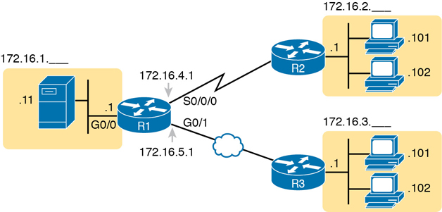
Figure 15-6 IPv4 Addresses Used in Example 15-2
Example 15-2 Configuring IP Addresses on Cisco Routers
R1# configure terminal
Enter configuration commands, one per line. End with CNTL/Z.
R1config)# interface G0/0
R1(config-if)# ip address 172.16.1.1 255.255.255.0
R1(config-if)# no shutdown
R1(config-if)# interface S0/0/0
R1(config-if)# ip address 172.16.4.1 255.255.255.0
R1(config-if)# no shutdown
R1(config-if)# interface G0/1/0
R1(config-if)# ip address 172.16.5.1 255.255.255.0
R1(config-if)# no shutdown
R1(config-if)# ^Z
R1#
Example 15-3 shows the output of the show protocols command. This command confirms the state of each of the three R1 interfaces in Figure 15-6 and the IP address and mask configured on those same interfaces.
Example 15-3 Verifying IP Addresses on Cisco Routers
R1# show protocols
Global values:
   Internet Protocol routing is enabled
Embedded-Service-Engine0/0 is administratively down, line protocol is down
GigabitEthernet0/0 is up, line protocol is up
   Internet address is 172.16.1.1/24
GigabitEthernet0/1 is administratively down, line protocol is down
Serial0/0/0 is up, line protocol is up
   Internet address is 172.16.4.1/24
Serial0/0/1 is administratively down, line protocol is down
GigabitEthernet0/1/0 is up, line protocol is up
   Internet address is 172.16.1.1/24
One of the first actions to take when verifying whether a router is working is to find the interfaces, check the interface status, and check to see whether the correct IP addresses and masks are used. Examples 15-1 and 15-3 showed samples of the key show commands, while Table 15-4 summarizes those commands and the types of information they display.
Table 15-4 Key Commands to List Router Interface Status
Command |
Lines of Output per Interface |
IP Configuration Listed |
Interface Status Listed? |
|---|---|---|---|
show ip interface brief |
1 |
Address |
Yes |
show protocols [type number] |
1 or 2 |
Address/mask |
Yes |
show interfaces [type number] |
Many |
Address/mask |
Yes |
Bandwidth and Clock Rate on Serial Interfaces
Cisco has included serial WAN topics in the CCNA exam topic list since its inception in 1998 until the CCNA 200-301 release in the year 2019. Because the CCNA 200-301 exam is the first to not mention serial technologies at all, this book includes some examples that show serial links. The exam might show them with the expectation that you at least understand basics, such as the fact that two routers can send data over a serial link if the router interfaces on both ends are up/up and the routers have IP addresses in the same subnet.
However, some of you will want to make serial links work in a lab because you have some serial interface cards in your lab. If so, take the time to look at a few pages in the section titled “Bandwidth and Clock Rate on Serial Interfaces,” in Appendix J, “Topics from Previous Editions,” which shows how to cable and configure a WAN serial link in the lab.
Router Auxiliary Port
Both routers and switches have a console port to allow administrative access, but most Cisco routers have an extra physical port called an auxiliary (Aux) port. The Aux port typically serves as a means to make a phone call to connect into the router to issue commands from the CLI.
The Aux port works like the console port, except that the Aux port is typically connected through a cable to an external analog modem, which in turn connects to a phone line. Then, the engineer uses a PC, terminal emulator, and modem to call the remote router. After being connected, the engineer can use the terminal emulator to access the router CLI, starting in user mode as usual.
Aux ports can be configured beginning with the line aux 0 command to reach aux line configuration mode. From there, all the commands for the console line, covered mostly in Chapter 6, can be used. For example, the login and password password subcommands on the aux line could be used to set up simple password checking when a user dials in.
Chapter Review
One key to doing well on the exams is to perform repetitive spaced review sessions. Review this chapter’s material using either the tools in the book or interactive tools for the same material found on the book’s companion website. Refer to the “Your Study Plan” element for more details. Table 15-5 outlines the key review elements and where you can find them. To better track your study progress, record when you completed these activities in the second column.
Table 15-5 Chapter Review Tracking
Review Element |
Review Date(s) |
Resource Used |
|---|---|---|
Review key topics |
Book, website |
|
Review key terms |
|
Book, website |
Answer DIKTA questions |
|
Book, PTP |
Review command tables |
|
Book |
Review memory tables |
|
Website |
Do labs |
|
Blog |
Watch video |
|
Website |
Review All the Key Topics
Table 15-6 Key Topics for Chapter 15
Key Topic |
Description |
Page Number |
|---|---|---|
List |
Steps required to install a router |
353 |
List |
Similarities between a router CLI and a switch CLI |
355 |
List |
Items covered for switches in Chapters 4 and 6 that differ in some way on routers |
356 |
Router interface status codes and their meanings |
359 |
|
Combinations of the two interface status codes and the likely reasons for each combination |
359 |
|
Commands useful to display interface IPv4 addresses, masks, and interface status |
361 |
Key Terms You Should Know
Command References
Tables 15-7 and 15-8 list configuration and verification commands used in this chapter. As an easy review exercise, cover the left column in a table, read the right column, and try to recall the command without looking. Then repeat the exercise, covering the right column, and try to recall what the command does.
Table 15-7 Chapter 15 Configuration Command Reference
Command |
Description |
|---|---|
interface type number |
Global command that moves the user into configuration mode of the named interface. |
ip address address mask |
Interface subcommand that sets the router’s IPv4 address and mask. |
[no] shutdown |
Interface subcommand that enables (no shutdown) or disables (shutdown) the interface. |
duplex {full | half | auto} |
Interface command that sets the duplex, or sets the use of IEEE autonegotiation, for router LAN interfaces that support multiple speeds. |
speed {10 | 100 | 1000} |
Interface command for router Gigabit (10/100/1000) interfaces that sets the speed at which the router interface sends and receives data. |
description text |
An interface subcommand with which you can type a string of text to document information about that particular interface. |
Table 15-8 Chapter 15 EXEC Command Reference
Command |
Purpose |
|---|---|
show interfaces [type number] |
Lists a large set of informational messages about each interface, or about the one specifically listed interface. |
show ip interface brief |
Lists a single line of information about each interface, including the IP address, line and protocol status, and the method with which the address was configured (manual or Dynamic Host Configuration Protocol [DHCP]). |
show protocols [type number] |
Lists information about the listed interface (or all interfaces if the interface is omitted), including the IP address, mask, and line/protocol status. |