Chapter 29. Building a Wireless LAN
This chapter covers the following exam topics:
2.0 Network Access
2.7 Describe physical infrastructure connections of WLAN components (AP, WLC, access/trunk ports, and LAG)
2.8 Describe AP and WLC management access connections (Telnet, SSH, HTTP, HTTPS, console, and TACACS+/RADIUS)
2.9 Configure the components of a wireless LAN access for client connectivity using GUI only, such as WLAN creation, security settings, QoS profiles, and advanced WLAN settings
5.0 Security Fundamentals
5.10 Configure WLAN using WPA2 PSK using the GUI
In Chapters 26 through 28, you learned about the fundamentals of wireless networks. As a CCNA, you will also need to know how to apply that knowledge toward building a functioning network with APs and a WLC.
In addition, based on the concepts you learned in Chapter 28, “Securing Wireless Networks,” you will be able to configure the WLAN to use WPA2-Personal.
“Do I Know This Already?” Quiz
Take the quiz (either here or use the PTP software) if you want to use the score to help you decide how much time to spend on this chapter. The letter answers are listed at the bottom of the page following the quiz. Appendix C, found both at the end of the book as well as on the companion website, includes both the answers and explanations. You can also find both answers and explanations in the PTP testing software.
Table 29-1 “Do I Know This Already?” Section-to-Question Mapping
Foundation Topics Section |
Questions |
|---|---|
Connecting a Cisco AP |
1–2 |
Accessing a Cisco WLC |
3 |
Connecting a Cisco WLC |
4–5 |
Configuring a WLAN |
6–8 |
1. Suppose you need to connect a lightweight AP to a network. Which one of the following link types would be necessary?
a. Access mode link
b. Trunk mode link
c. LAG mode link
d. EtherChannel link
2. An autonomous AP will be configured to support three WLANs that correspond to three VLANs. The AP will connect to the network over which one of the following?
a. Access mode link
b. Trunk mode link
c. LAG mode link
d. EtherChannel link
3. Suppose you would like to connect to a WLC to configure a new WLAN on it. Which one of the following is a valid method to use?
a. SSH
b. HTTPS
c. HTTP
d. All of these answers are correct.
4. Which one of the following correctly describes the single logical link formed by bundling all of a controller’s distribution system ports together?
a. PHY
b. DSP
c. LAG
d. GEC
5. Which one of the following controller interfaces maps a WLAN to a VLAN?
a. Bridge interface
b. Virtual interface
c. WLAN interface
d. Dynamic interface
6. Which two of the following things are bound together when a new WLAN is created?
a. VLAN
b. AP
c. Controller interface
d. SSID
7. What is the maximum number of WLANs you can configure on a Cisco wireless controller?
a. 8
b. 16
c. 512
d. 1024
8. Which of the following parameters are necessary when creating a new WLAN with the controller GUI? (Choose all that apply.)
a. SSID
b. VLAN number
c. Interface
d. BSSID
e. IP subnet
Answers to the “Do I Know This Already?” quiz:
1 A
2 B
3 D
4 C
5 D
6 C, D
7 C
8 A, C
Foundation Topics
Connecting a Cisco AP
A Cisco wireless network can consist of autonomous APs or lightweight APs that are coupled with one or more wireless LAN controllers. Both types of APs are covered in Chapter 27, “Analyzing Cisco Wireless Architectures,” from a functional perspective. You should also understand how to connect the wired side of each type of AP so that it can pass traffic between the appropriate VLANs and WLANs.
Recall that an autonomous AP is a standalone device; nothing else is needed to forward Ethernet frames from a wired VLAN to a wireless LAN, and vice versa. In effect, the AP maps each VLAN to a WLAN and BSS. The autonomous AP has a single wired Ethernet interface, as shown in the left portion of Figure 29-1, which means that multiple VLANs must be brought to it over a trunk link.
Note
A switch port providing a wired connection to an AP must be configured to support either access or trunk mode. In trunk mode, 802.1Q encapsulation tags each frame according to the VLAN number it came from. The wireless side of an AP inherently trunks 802.11 frames by marking them with the BSSID of the WLAN where they belong.
A lightweight AP also has a single wired Ethernet interface; however, it must be paired with a WLC to be fully functional. Wired VLANs that terminate at the WLC can be mapped to WLANs that emerge at the AP. Even though multiple VLANs are being extended from the WLC to the AP, they are all carried over the CAPWAP tunnel between the two. That means the AP needs only an access link to connect to the network infrastructure and terminate its end of the tunnel, as shown in the right portion of Figure 29-1.

Figure 29-1 Comparing Connections to Autonomous and Lightweight APs
To configure and manage Cisco APs, you can connect a serial console cable from your PC to the console port on the AP. Once the AP is operational and has an IP address, you can also use Telnet or SSH to connect to its CLI over the wired network. Autonomous APs support browser-based management sessions via HTTP and HTTPS. You can manage lightweight APs from a browser session to the WLC.
Accessing a Cisco WLC
To connect and configure a WLC, you will need to open a web browser to the WLC’s management address with either HTTP or HTTPS. This can be done only after the WLC has an initial configuration and a management IP address assigned to its management interface. The web-based GUI provides an effective way to monitor, configure, and troubleshoot a wireless network. You can also connect to a WLC with an SSH session, where you can use its CLI to monitor, configure, and debug activity.
Both the web-based GUI and the CLI require management users to log in. Users can be authenticated against an internal list of local usernames or against an authentication, authorization, and accounting (AAA) server, such as TACACS+ or RADIUS.
When you first open a web browser to the management address, you will see the initial login screen. Click on the Login button, as shown in Figure 29-2; then enter your user credentials as you are prompted for them.
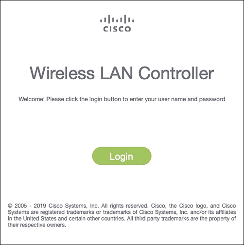
Figure 29-2 Accessing a WLC with a Web Browser
Note
The CCNA exam objectives focus on using the WLC GUI to configure a WLAN and a security suite. Therefore, the examples in this section assume that someone has already entered an initial configuration to give the WLC a working IP address for management.
When you are successfully logged in, the WLC will display a monitoring dashboard similar to the one shown in Figure 29-3. You will not be able to make any configuration changes there, so you must click on the Advanced link in the upper-right corner. This will bring up the full WLC GUI, as shown in Figure 29-4.
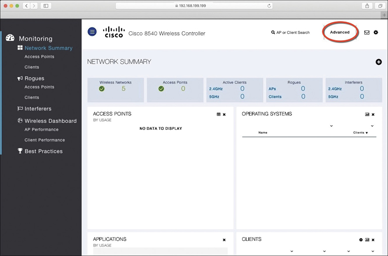
Figure 29-3 Accessing the Advanced Configuration Interface
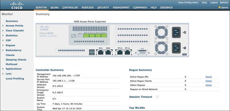
Figure 29-4 The Advanced WLC Configuration GUI
Notice the tabs across the top of the screen in Figure 29-4. You can select categories of functions from among Monitor, WLANs, Controller, Wireless, Security, and so on. As you select one of these categories, the vertical list of functions at the left side of the screen will change accordingly. You can expand the list entries if needed and select one to work on. The main screen area will display all of the relevant fields and options you can edit as you make configuration changes. You will get a feel for which tabs and list items you should use as you work through the remainder of the chapter.
Connecting a Cisco WLC
Connecting a Cisco wireless LAN controller to the network is not quite as straightforward because it has several different types of connections. From your work with Cisco routers and switches, you probably know that the terms interface and port are usually interchangeable. For example, switches can come in 48-port models, and you apply configuration changes to the corresponding interfaces. Cisco wireless controllers differ a bit; ports and interfaces refer to different concepts.
Controller ports are physical connections made to an external wired or switched network, whereas interfaces are logical connections made internally within the controller. The following sections explain each connection type in more detail. You will learn more about configuring ports and interfaces in the “Configuring a WLAN” section later in the chapter.
Using WLC Ports
You can connect several different types of controller ports to your network, as shown in Figure 29-5 and discussed in the following list:
Service port: Used for out-of-band management, system recovery, and initial boot functions; always connects to a switch port in access mode
Distribution system port: Used for all normal AP and management traffic; usually connects to a switch port in 802.1Q trunk mode
Console port: Used for out-of-band management, system recovery, and initial boot functions; asynchronous connection to a terminal emulator (9600 baud, 8 data bits, 1 stop bit, by default)
Redundancy port: Used to connect to a peer controller for high availability (HA) operation

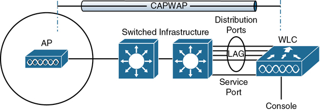
Figure 29-5 Cisco Wireless LAN Controller Ports
Controllers can have a single service port that must be connected to a switched network. Usually, the service port is assigned to a management VLAN so that you can access the controller with SSH or a web browser to perform initial configuration or for maintenance. Notice that the service port supports only a single VLAN, so the corresponding switch port must be configured for access mode only.
Controllers also have multiple distribution system ports that you must connect to the network. These ports carry most of the data coming to and going from the controller. For example, the CAPWAP tunnels (control and data) that extend to each of a controller’s APs pass across the distribution system ports. Client data also passes from wireless LANs to wired VLANs over the ports. In addition, any management traffic using a web browser, SSH, Simple Network Management Protocol (SNMP), Trivial File Transfer Protocol (TFTP), and so on, normally reaches the controller in-band through the ports.
Note
You might be thinking that distribution system ports is an odd name for what appear to be regular data ports. Recall from the section titled “Wireless LAN Topologies” in Chapter 26, “Fundamentals of Wireless Networks,” that the wired network that connects APs together is called the distribution system (DS). With the split MAC architecture, the point where APs touch the DS is moved upstream to the WLC instead.
Because the distribution system ports must carry data that is associated with many different VLANs, VLAN tags and numbers become very important. For that reason, the distribution system ports always operate in 802.1Q trunking mode. When you connect the ports to a switch, you should also configure the switch ports for unconditional 802.1Q trunk mode.
The distribution system ports can operate independently, each one transporting multiple VLANs to a unique group of internal controller interfaces. For resiliency, you can configure distribution system ports in redundant pairs. One port is primarily used; if it fails, a backup port is used instead.
To get the most use out of each distribution system port, you can configure all of them to operate as a single logical group, much like an EtherChannel or port-channel on a switch. Controller distribution system ports can be configured as a link aggregation group (LAG) such that they are bundled together to act as one larger link. In Figure 29-5, the four distribution system ports are configured as a LAG. With a LAG configuration, traffic can be load-balanced across the individual ports that make up the LAG. In addition, LAG offers resiliency; if one individual port fails, traffic will be redirected to the remaining working ports instead.
Note
Be aware that even though the LAG acts as a traditional EtherChannel, Cisco WLCs do not support any link aggregation negotiation protocol, like LACP or PaGP, at all. Therefore, you must configure the switch ports as an unconditional or always-on EtherChannel.
Using WLC Interfaces
Through its distribution system ports, a controller can connect to multiple VLANs on the switched network. Internally, the controller must somehow map those wired VLANs to equivalent logical wireless networks. For example, suppose that VLAN 10 is set aside for wireless users in the Engineering division of a company. That VLAN must be connected to a unique wireless LAN that exists on a controller and its associated APs. The wireless LAN must then be extended to every client that associates with the Service Set Identifier (SSID) “Engineering.”
Cisco wireless controllers provide the necessary connectivity through internal logical interfaces, which must be configured with an IP address, subnet mask, default gateway, and a Dynamic Host Configuration Protocol (DHCP) server. Each interface is then assigned to a physical port and a VLAN ID. You can think of an interface as a Layer 3 termination on a VLAN.
Cisco controllers support the following interface types, also shown in Figure 29-6.
Management interface: Used for normal management traffic, such as RADIUS user authentication, WLC-to-WLC communication, web-based and SSH sessions, SNMP, Network Time Protocol (NTP), syslog, and so on. The management interface is also used to terminate CAPWAP tunnels between the controller and its APs.
Redundancy management: The management IP address of a redundant WLC that is part of a high availability pair of controllers. The active WLC uses the management interface address, while the standby WLC uses the redundancy management address.
Virtual interface: IP address facing wireless clients when the controller is relaying client DHCP requests, performing client web authentication, and supporting client mobility.
Service port interface: Bound to the service port and used for out-of-band management.
Dynamic interface: Used to connect a VLAN to a WLAN.
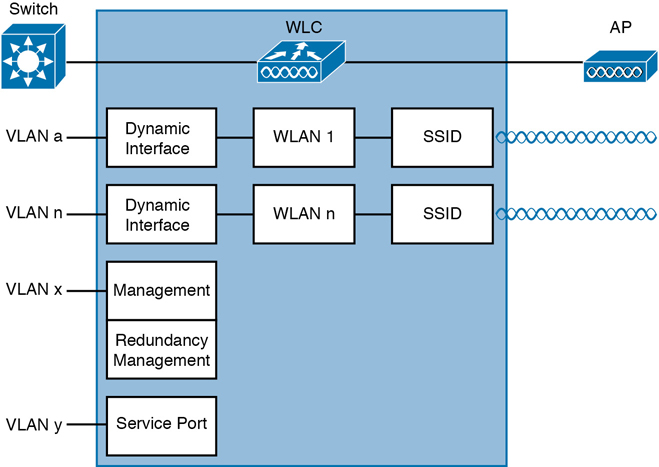
Figure 29-6 Cisco Wireless LAN Controller Interfaces
The management interface faces the switched network, where management users and APs are located. Management traffic will usually consist of protocols like HTTPS, SSH, SNMP, NTP, TFTP, and so on. In addition, management interface traffic consists of CAPWAP packets that carry control and data tunnels to and from the APs.
The virtual interface is used only for certain client-facing operations. For example, when a wireless client issues a request to obtain an IP address, the controller can relay the request on to an actual DHCP server that can provide the appropriate IP address. From the client’s perspective, the DHCP server appears to be the controller’s virtual interface address. Clients may see the virtual interface’s address, but that address is never used when the controller communicates with other devices on the switched network.
Because the virtual interface is used only for some client management functions, you should configure it with a unique, nonroutable address. For example, you might use 10.1.1.1 because it is within a private address space defined in RFC 1918.
Note
Traditionally, many people have assigned IP address 1.1.1.1 to the virtual interface. Although it is a unique address, it is routable and already in use elsewhere on the Internet. A better practice is to use an IP address from the RFC 1918 private address space that is unused or reserved, such as 192.168.1.1. You could also use a reserved address from RFC 5737 (192.0.2.0/24) that is set aside for documentation purposes and is never used.
The virtual interface address is also used to support client mobility. For that reason, every controller that exists in the same mobility group should be configured with a virtual address that is identical to the others. By using one common virtual address, all the controllers will appear to operate as a cluster as clients roam from controller to controller.
Dynamic interfaces map WLANs to VLANs, making the logical connections between wireless and wired networks. You will configure one dynamic interface for each wireless LAN that is offered by the controller’s APs and then map the interface to the WLAN. Each dynamic interface must also be configured with its own IP address and can act as a DHCP relay for wireless clients. To filter traffic passing through a dynamic interface, you can configure an optional access list.
Configuring a WLAN
A wireless LAN controller and an access point work in concert to provide network connectivity to wireless clients. From a wireless perspective, the AP advertises a Service Set Identifier (SSID) for the client to join. From a wired perspective, the controller connects to a virtual LAN (VLAN) through one of its dynamic interfaces. To complete the path between the SSID and the VLAN, as illustrated in Figure 29-7, you must first define a WLAN on the controller.
Note
Two of the CCNA exam objectives involve configuring a WLAN for client connectivity with WPA2 and a PSK using only the controller GUI. As you work through this section, you will find that it presents a complete WLAN example that is based on the topology shown in Figure 29-7 using the WPA2-Personal (PSK) security model.
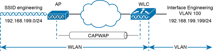
Figure 29-7 Connecting Wired and Wireless Networks with a WLAN
The controller will bind the WLAN to one of its interfaces and then push the WLAN configuration out to all of its APs by default. From that point on, wireless clients will be able to learn about the new WLAN by receiving its beacons and will be able to probe and join the new BSS.
Like VLANs, you can use WLANs to segregate wireless users and their traffic into logical networks. Users associated with one WLAN cannot cross over into another one unless their traffic is bridged or routed from one VLAN to another through the wired network infrastructure.
Before you begin to create new WLANs, it is usually wise to plan your wireless network first. In a large enterprise, you might have to support a wide variety of wireless devices, user communities, security policies, and so on. You might be tempted to create a new WLAN for every occasion, just to keep groups of users isolated from each other or to support different types of devices. Although that is an appealing strategy, you should be aware of two limitations:
Cisco controllers support a maximum of 512 WLANs, but only 16 of them can be actively configured on an AP.
Advertising each WLAN to potential wireless clients uses up valuable airtime.
Every AP must broadcast beacon management frames at regular intervals to advertise the existence of a BSS. Because each WLAN is bound to a BSS, each WLAN must be advertised with its own beacons. Beacons are normally sent 10 times per second, or once every 100 ms, at the lowest mandatory data rate. The more WLANs you have created, the more beacons you will need to announce them.
Even further, the lower the mandatory data rate, the more time each beacon will take to be transmitted. The end result is this: if you create too many WLANs, a channel can be starved of any usable airtime. Clients will have a hard time transmitting their own data because the channel is overly busy with beacon transmissions coming from the AP. As a rule of thumb, always limit the number of WLANs to five or fewer; a maximum of three WLANs is best.
By default, a controller has a limited initial configuration, so no WLANs are defined. Before you create a new WLAN, think about the following parameters it will need to have:
SSID string
Controller interface and VLAN number
Type of wireless security needed
As you work through this section, you will create the appropriate dynamic controller interface to support the new WLAN; then you will enter the necessary WLAN parameters. Each configuration step is performed using a web browser session that is connected to the WLC’s management IP address.
Step 1. Configure a RADIUS Server
If your new WLAN will use a security scheme that requires a RADIUS server, such as WPA2-Enterprise or WPA3-Enterprise, you will need to define the server first. Select Security > AAA > RADIUS > Authentication to see a list of servers that have already been configured, as shown in Figure 29-8. If multiple servers are defined, the controller will try them in sequential order. Click New to create a new server.
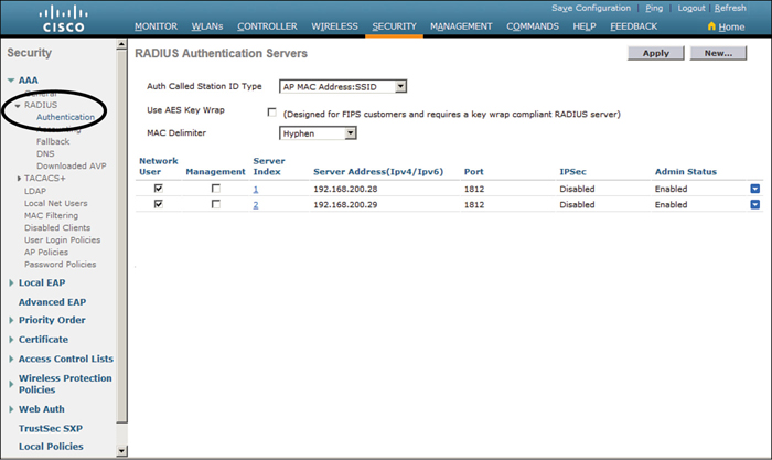
Figure 29-8 Displaying the List of RADIUS Authentication Servers
Next, enter the server’s IP address, shared secret key, and port number, as shown in Figure 29-9. Because the controller already had two other RADIUS servers configured, the server at 192.168.200.30 will be index number 3. Be sure to set the server status to Enabled so that the controller can begin using it. At the bottom of the page, you can select the type of user that will be authenticated with the server. Check Network User to authenticate wireless clients or Management to authenticate wireless administrators that will access the controller’s management functions. Click Apply to complete the server configuration.
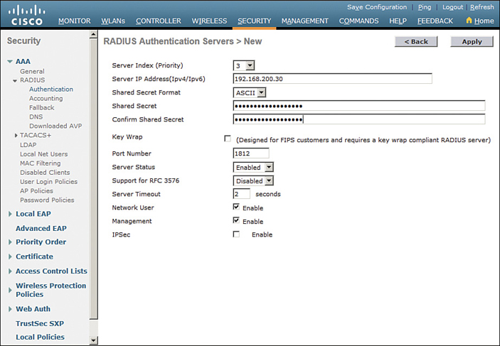
Figure 29-9 Configuring a New RADIUS Server
Step 2. Create a Dynamic Interface
In the “Using WLC Interfaces” section of this chapter, you learned about the different types of controller interfaces. A dynamic interface is used to connect the controller to a VLAN on the wired network. When you create a WLAN, you will bind the dynamic interface (and VLAN) to a wireless network.
To create a new dynamic interface, navigate to Controller > Interfaces. You should see a list of all the controller interfaces that are currently configured. In Figure 29-10, two interfaces named “management” and “virtual” already exist. Click the New button to define a new interface. Enter a name for the interface and the VLAN number it will be bound to. In Figure 29-11, the interface named Engineering is mapped to wired VLAN 100. Click the Apply button.
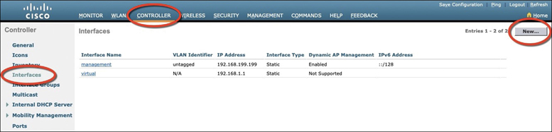
Figure 29-10 Displaying a List of Dynamic Interfaces
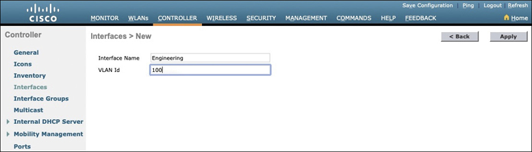
Figure 29-11 Defining a Dynamic Interface Name and VLAN ID
Next, enter the IP address, subnet mask, and gateway address for the interface. You should also define primary and secondary DHCP server addresses that the controller will use when it relays DHCP requests from clients that are bound to the interface. Figure 29-12 shows how the interface named Engineering has been configured with IP address 192.168.100.10, subnet mask 255.255.255.0, gateway 192.168.100.1, and DHCP servers 192.168.1.17 and 192.168.1.18. Click the Apply button to complete the interface configuration and return to the list of interfaces.
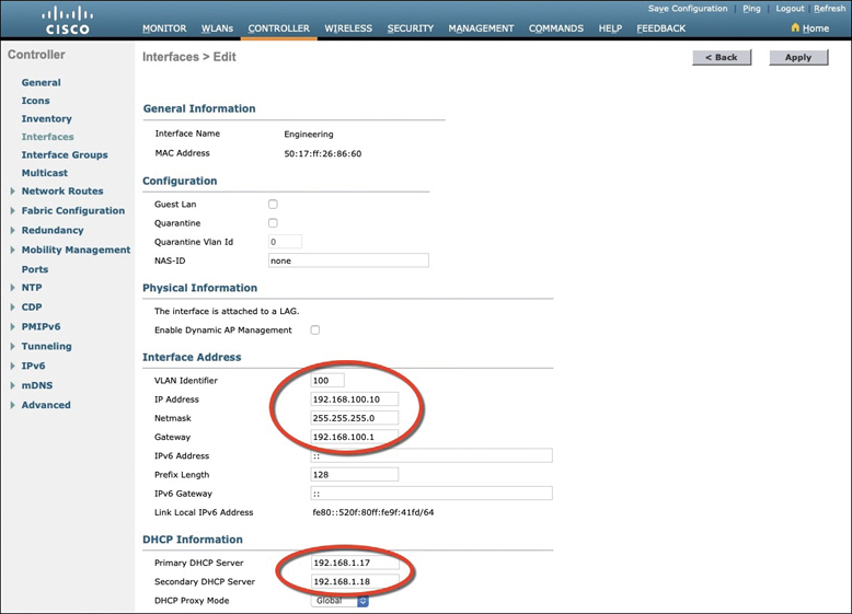
Figure 29-12 Editing the Dynamic Interface Parameters
Step 3. Create a New WLAN
You can display a list of the currently defined WLANs by selecting WLANs from the top menu bar. In Figure 29-13, the controller does not have any WLANs already defined. You can create a new WLAN by selecting Create New from the drop-down menu and then clicking the Go button.
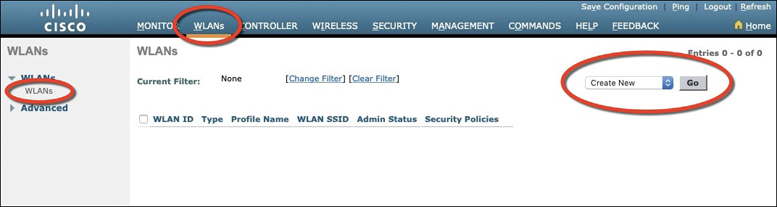
Figure 29-13 Displaying a List of WLANs
Next, enter a descriptive name as the profile name and the SSID text string. In Figure 29-14, the profile name and SSID are identical, just to keep things straightforward. The ID number is used as an index into the list of WLANs that are defined on the controller. The ID number becomes useful when you use templates in Prime Infrastructure (PI) to configure WLANs on multiple controllers at the same time.
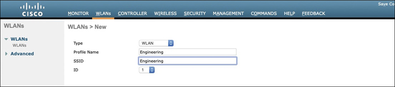
Figure 29-14 Creating a New WLAN
Note
WLAN templates are applied to specific WLAN ID numbers on controllers. The WLAN ID is only locally significant and is not passed between controllers. As a rule, you should keep the sequence of WLAN names and IDs consistent across multiple controllers so that any configuration templates you use in the future will be applied to the same WLANs on each controller.
Click the Apply button to create the new WLAN. The next page will allow you to edit four categories of parameters, corresponding to the tabs across the top as shown in Figure 29-15. By default, the General tab is selected.
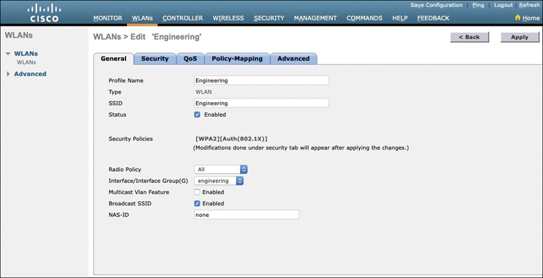
Figure 29-15 Configuring the General WLAN Parameters
You can control whether the WLAN is enabled or disabled with the Status check box. Even though the General page shows a specific security policy for the WLAN (the default WPA2 with 802.1x), you can make changes in a later step through the Security tab.
Under Radio Policy, select the type of radio that will offer the WLAN. By default, the WLAN will be offered on all radios that are joined with the controller. You can select a more specific policy with 802.11a only, 802.11a/g only, 802.11g only, or 802.11b/g only. For example, if you are creating a new WLAN for devices that have only a 2.4-GHz radio, it probably does not make sense to advertise the WLAN on both 2.4- and 5-GHz AP radios.
Next, select which of the controller’s dynamic interfaces will be bound to the WLAN. By default, the management interface is selected. The drop-down list contains all the interface names that are available. In Figure 29-15, the new engineering WLAN will be bound to the Engineering interface.
Finally, use the Broadcast SSID check box to select whether the APs should broadcast the SSID name in the beacons they transmit. Broadcasting SSIDs is usually more convenient for users because their devices can learn and display the SSID names automatically. In fact, most devices actually need the SSID in the beacons to understand that the AP is still available for that SSID. Hiding the SSID name, by not broadcasting it, does not really provide any worthwhile security. Instead, it just prevents user devices from discovering an SSID and trying to use it as a default network.
Configuring WLAN Security
Select the Security tab to configure the security settings. By default, the Layer 2 Security tab is selected. From the Layer 2 Security drop-down menu, select the appropriate security scheme to use. Table 29-2 lists the types that are available.
Table 29-2 Layer 2 WLAN Security Type
Option |
Description |
|---|---|
None |
Open authentication |
WPA+WPA2 |
Wi-Fi protected access WPA or WPA2 |
802.1x |
EAP authentication with dynamic WEP |
Static WEP |
WEP key security |
Static WEP + 802.1x |
EAP authentication or static WEP |
CKIP |
Cisco Key Integrity Protocol |
None + EAP Passthrough |
Open authentication with remote EAP authentication |
As you select a security type, be sure to remember which choices are types that have been deprecated or proven to be weak, and avoid them if possible. Further down the screen, you can select which specific WPA, WPA2, and WPA3 methods to support on the WLAN. You can select more than one, if you need to support different types of wireless clients that require several security methods.
In Figure 29-16, WPA+WPA2 has been selected from the pull-down menu; then only WPA2 and AES encryption have been selected. WPA and TKIP have been avoided because they are legacy, deprecated methods. Under the Authentication Key Management section, you can select the authentication methods the WLAN will use. Only PSK has been selected in the figure, so the WLAN will allow only WPA2-Personal with pre-shared key authentication.
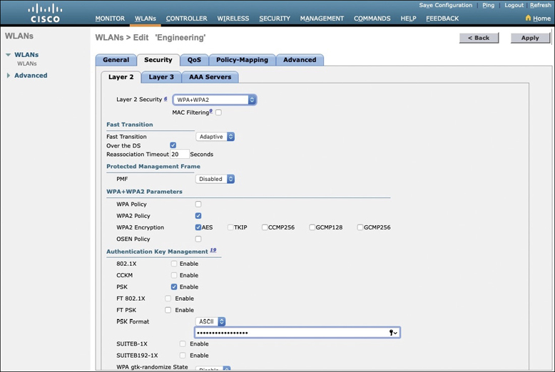
Figure 29-16 Configuring Layer 2 WLAN Security
To use WPA2-Enterprise, the 802.1X option would be selected. In that case, 802.1x and EAP would be used to authenticate wireless clients against one or more RADIUS servers. The controller would use servers from the global list you have defined under Security > AAA > RADIUS > Authentication, as described in the “Step 1. Configure a RADIUS Server” section in this chapter. To specify which servers the WLAN should use, you would select the Security tab and then the AAA Servers tab in the WLAN edit screen. You can identify up to six specific RADIUS servers in the WLAN configuration. Beside each server, select a specific server IP address from the drop-down menu of globally defined servers. The servers are tried in sequential order until one of them responds. Although the example in this chapter uses WPA2-Personal, Figure 29-17 shows what a WLAN configured for WPA2-Enterprise might look like, with servers 1 through 3 being set to 192.168.200.28, 192.168.200.29, and 192.168.200.30, respectively.
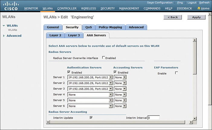
Figure 29-17 Selecting RADIUS Servers for WLAN Authentication
By default, a controller will contact a RADIUS server from its management interface. You can override this behavior by checking the box next to Radius Server Overwrite Interface so that the controller sources RADIUS requests from the dynamic interface that is associated with the WLAN.
Configuring WLAN QoS
Select the QoS tab to configure quality of service settings for the WLAN, as shown in Figure 29-18. By default, the controller will consider all frames in the WLAN to be normal data, to be handled in a “best effort” manner. You can set the Quality of Service (QoS) drop-down menu to classify all frames in one of the following ways:
Platinum (voice)
Gold (video)
Silver (best effort)
Bronze (background)
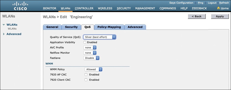
Figure 29-18 Configuring QoS Settings
You can also set the Wi-Fi Multimedia (WMM) policy, call admission control (CAC) policies, and bandwidth parameters on the QoS page. You can learn more about QoS in the CCNA 200-301 Official Cert Guide, Volume 2, in Chapter 11, “Quality of Service.”
Configuring Advanced WLAN Settings
Finally, you can select the Advanced tab to configure a variety of advanced WLAN settings. From the page shown in Figure 29-19, you can enable functions such as coverage hole detection, peer-to-peer blocking, client exclusion, client load limits, and so on.
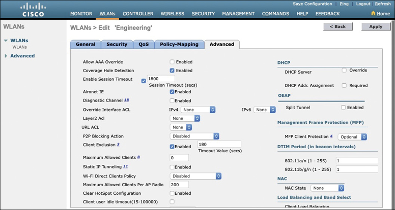
Figure 29-19 Configuring Advanced WLAN Settings
Although most of the advanced settings are beyond the scope of the CCNA objectives, you should be aware of a few defaults that might affect your wireless clients.
By default, client sessions with the WLAN are limited to 1800 seconds (30 minutes). Once that session time expires, a client will be required to reauthenticate. This setting is controlled by the Enable Session Timeout check box and the Timeout field.
A controller maintains a set of security policies that are used to detect potentially malicious wireless clients. If a client exhibits a certain behavior, the controller can exclude it from the WLAN for a period of time. By default, all clients are subject to the policies configured under Security > Wireless Protection Policies > Client Exclusion Policies. These policies include excessive 802.11 association failures, 802.11 authentication failures, 802.1x authentication failures, web authentication failures, and IP address theft or reuse. Offending clients will be automatically excluded or blocked for 60 seconds, as a deterrent to attacks on the wireless network.
Note
Is 60 seconds really enough time to deter an attack coming from a wireless client? In the case of a brute-force attack, where passwords are guessed from a dictionary of possibilities, 60 seconds is enough to disrupt and delay an attacker’s progress. What might have taken 2 minutes to find a matching password without an exclusion policy would take 15 years with one.
Finalizing WLAN Configuration
When you are satisfied with the settings in each of the WLAN configuration tabs, click the Apply button in the upper-right corner of the WLAN Edit screen. The WLAN will be created and added to the controller configuration. In Figure 29-20, the Engineering WLAN has been added as WLAN ID 1 and is enabled for use.
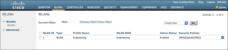
Figure 29-20 Displaying WLANs Configured on a Controller
Be aware that, by default, a controller will not allow management traffic that is initiated from a WLAN. That means you (or anybody else) cannot access the controller GUI or CLI from a wireless device that is associated to the WLAN. This is considered to be a good security practice because the controller is kept isolated from networks that might be easily accessible or where someone might eavesdrop on the management session traffic. Instead, you can access the controller through its wired interfaces.
You can change the default behavior on a global basis (all WLANs) by selecting the Management tab and then selecting Mgmt Via Wireless, as shown in Figure 29-21. Check the box to allow management sessions from any WLAN that is configured on the controller.
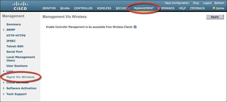
Figure 29-21 Configuring Management Access from Wireless Networks
Chapter Review
Review this chapter’s material using either the tools in the book or the interactive tools for the same material found on the book’s companion website. Table 29-3 outlines the key review elements and where you can find them. To better track your study progress, record when you completed these activities in the second column.
Table 29-3 Chapter Review Tracking
Review Element |
Review Date(s) |
Resource Used |
|---|---|---|
Review key topics |
|
Book, website |
Review key terms |
|
Book, website |
Answer DIKTA questions |
|
Book, PTP |
Review All the Key Topics
Review the most important topics in this chapter, noted with the Key Topic icon in the outer margin of the page. Table 29-4 lists a reference of these key topics and the page numbers on which each is found.
Table 29-4 Key Topics for Chapter 29
Key Topic Element |
Description |
Page Number |
|---|---|---|
Physical connections to an AP |
669 |
|
Wireless LAN controller ports |
672 |
|
Wireless LAN controller interfaces |
674 |
|
Creating a WLAN |
675 |
|
Configuring WLAN security |
681 |