CHAPTER 7
Layer 2 Switching
The following CCNA exam topics are covered in this chapter: 1.0 Network Fundamentals 5.0 Security Fundamentals
You should already know that we rely on switching to break up large collision domains into smaller ones and that a collision domain is a network segment with two or more devices sharing the same bandwidth. A hub network is a good example of this type of technology, but since each port on a switch is actually its own collision domain, we can create a much more efficient network simply by replacing hubs with switches. Switches have changed the way networks are designed and implemented. If a pure switched design is implemented well, the result will be a clean, cost-effective, and resilient internetwork. Coming up, I’ll compare how networks were designed before and after switching technologies were introduced. I’ll be using three switches to begin configuring our switched network and we’ll continue configuring them in Chapter 8, “VLANs and Inter-VLAN Routing.” Bridges use software to create and manage a Content Addressable Memory (CAM) filter table. Instead, the fast switches we use today rely upon application-specific integrated circuits (ASICs) to build and maintain their MAC filter tables. This is a big difference, but it’s still okay to think of a layer 2 switch as a multiport bridge because their basic reason for being is the same: to break up collision domains. Layer 2 switches and bridges are faster than routers because they don’t waste time looking at the Network layer header information. Instead, they look at the frame’s hardware addresses before deciding to either forward, flood, or drop the frame. Unlike hubs, switches create private, dedicated collision domains and provide independent bandwidth exclusive on each port. Here’s a list of four important advantages we gain when using layer 2 switching:
A big reason layer 2 switching is so efficient is that no modification to the data packet takes place. The device only reads the frame encapsulating the packet, which makes the switching process considerably faster and less vulnerable to errors than routing processes are. Plus, if you use layer 2 switching for both workgroup connectivity and network segmentation (breaking up collision domains), you can create more network segments than you can with traditional routed networks. Another nice benefit gained via layer 2 switching is it increases bandwidth for each user because, again, each connection, or interface into the switch, is its own, self-contained collision domain. There are three distinct functions of layer 2 switching you need to remember:
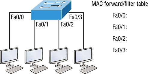
address learning, forward/filter decisions, and loop avoidance. Address learning Layer 2 switches remember the source hardware address of each frame received on an interface and enter this information into a MAC database called a forward/filter table. The old name for this table was called Content Addressable Memory (CAM), and the table is still sometimes referred either way. Forward/filter decisions When a frame is received on an interface, the switch looks at the destination hardware address, then chooses the appropriate exit interface for it in the MAC database. This way, the frame is only forwarded out of the correct destination port. Loop avoidance If multiple connections between switches are created for redundancy, network loops can occur. Spanning Tree Protocol (STP) is used to prevent network loops while still permitting redundancy. Next, I’m going to talk about address learning and forward/filtering decisions. Loop avoidance is beyond the scope of the objectives being covered in this chapter. When a switch is first powered on, the MAC forward/filter table (CAM) is empty, as shown in Figure 7.1.
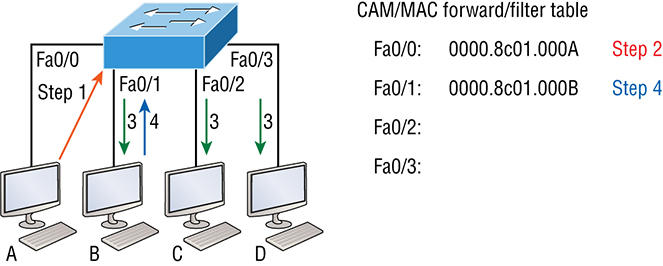
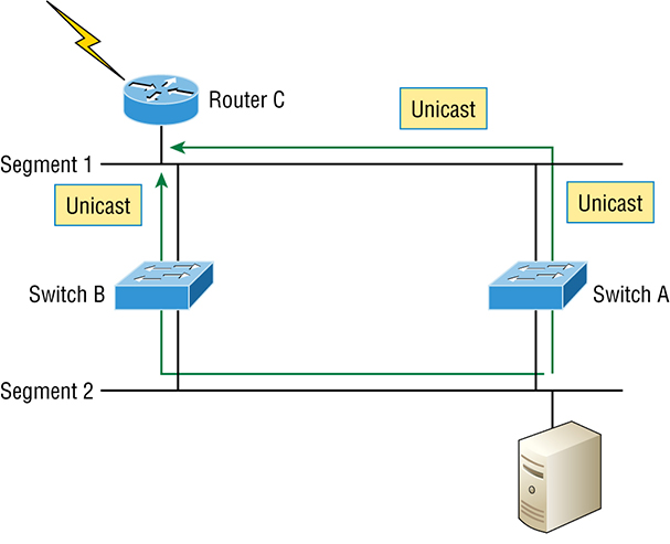
Figure 7.1 Empty forward/filter table on a switch When a device transmits and an interface receives a frame, the switch places the frame’s source address in the MAC forward/filter table, allowing it to refer to the precise interface the sending device is located on. The switch then has no choice but to flood the network with this frame out of every port except the source port because it has no idea where the destination device is actually located. If a device answers this flooded frame and sends a frame back, then the switch will take the source address from that frame and place that MAC address in its database as well, associating this address with the interface that received the frame. Because the switch now has both of the relevant MAC addresses in its filtering table, the two devices can now make a point-to-point connection. The switch doesn’t need to flood the frame as it did the first time because now the frames will only be forwarded between these two devices. This is exactly why layer 2 switches are so superior to hubs. In a hub network, all frames are forwarded out all ports every time—no matter what. Figure 7.2 shows the processes involved in building a MAC database. Figure 7.2 How switches learn hosts’ locations This figure shows four hosts attached to a switch. When the switch is powered on, it has nothing in its MAC address forward/filter table, just as in Figure 7.1. But when the hosts start communicating, the switch places the source hardware address of each frame into the table along with the port that the frame’s source address corresponds to. Let me give you an example of how a forward/filter table is populated using Figure :
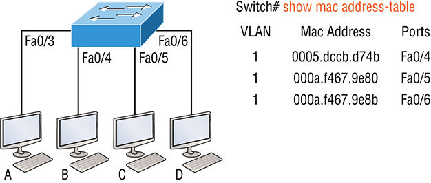
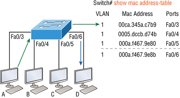
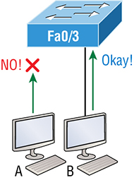
If Host A and Host B don’t communicate to the switch again within a certain time period, the switch will flush their entries from the database to keep it current. When a frame arrives at a switch interface, the destination hardware address is compared to the forward/filter MAC database. If the destination hardware address is known and listed in the database, the frame is only sent out of the appropriate exit interface. The switch won’t transmit the frame out any interface except for the destination interface, which preserves bandwidth on the other network segments. This process is called frame filtering. But if the destination hardware address isn’t listed in the MAC database, then the frame will be flooded out all active interfaces except the interface it was received on. If a device answers the flooded frame, the MAC database is then updated with the device’s location—its correct interface. If a host or server sends a broadcast on the LAN, by default, the switch will flood the frame out all active ports except the source port. Remember, the switch creates smaller collision domains, but it’s always still one large broadcast domain by default. In Figure 7.3, Host A sends a data frame to Host D. What do you think the switch will do when it receives the frame from Host A? Figure 7.3 Forward/filter table Let’s examine Figure 7.4 to find the answer. Figure 7.4 Forward/filter table answer Since Host A’s MAC address is not in the forward/filter table, the switch will add the source address and port to the MAC address table, then forward the frame to Host D. It’s important to remember that the source MAC is always checked first to make sure it’s in the CAM table. After that, if Host D’s MAC address wasn’t found in the forward/filter table, the switch would’ve flooded the frame out all ports except for port Fa0/3 because that’s the specific port the frame was received on. Now let’s take a look at the output that results from using a show mac address-table command: Now, let’s say the preceding switch received a frame with the following MAC addresses: Source MAC: 0005.dccb.d74b Destination MAC: 000a.f467.9e8c How will the switch handle this frame? The right answer is that the destination MAC address will be found in the MAC address table, and the frame will only be forwarded out Fa0/3. Never forget that if the destination MAC address isn’t found in the forward/filter table, the frame will be forwarded out all of the switch’s ports except for the one on which it was originally received in an attempt to locate the destination device. Now that you can see the MAC address table and how switches add host addresses to the forward filter table, how do think we can secure it from unauthorized users? It’s usually a bad idea to have your switches available for anyone to just plug into and play around with. We worry about wireless security, so why wouldn’t we demand switch security just as much, if not more? But just how do we actually prevent someone from simply plugging a host into one of our switch ports—or worse, adding a hub, switch, or access point into the Ethernet jack in their office? By default, MAC addresses will dynamically appear in your MAC forward/filter database, and you can stop them in their tracks by using port security! Figure 7.5 shows two hosts connected to the single switch port Fa0/3 via either a hub or access point (AP). Figure 7.5 “Port security” on a switch port restricts port access by MAC address. Port Fa0/3 is configured to observe and allow only certain MAC addresses to associate with the specific port. So in this example, Host A is denied access, but Host B is allowed to associate with the port. By using port security, you can limit the number of MAC addresses that can be assigned dynamically to a port, set static MAC addresses, and—here’s my favorite part—set penalties for users who abuse your policy! Personally, I like to have the port shut down when the security policy is violated. Making abusers bring me a memo from their boss explaining why they violated the security policy is just so satisfying, so I’ll also require something like that before I’ll enable their port again. Things like this really help people remember to behave! This is all good, but you still need to balance your particular security needs with the time that implementing and managing them will require. If you have tons of time on your hands, then go ahead and seriously lock your network down like a vault, but if you’re busy like the rest of us, rest assured that there are ways to secure things nicely without an overwhelming amount of administrative overhead. First, and painlessly, always remember to shut down unused ports or assign them to an unused VLAN. All ports are enabled by default, so you need to make sure there’s no access to unused switch ports! Here are your options for configuring port security: Most Cisco switches ship with their ports in desirable mode, which means those ports will desire to trunk when they sense another switch has been connected. So first, we need to change the port and make it an access port instead. If we don’t do that, we won’t be able to configure port security on it at all. Once that’s out of the way, we can move on using our port-security commands, never forgetting to enable port security on the interface with the basic command switchport port-security. Notice that I did this after I made the port an access port! The preceding output clearly illustrates that the switchport port-security command can be used with four options. While it’s true you can use the switchport port-security mac-address
mac-address command to assign individual MAC addresses to each switch port, if you go with that option, you’d better have boatloads of time on your hands! You can configure the device to take one of the following actions when a security violation occurs by using the switchport port-security command:
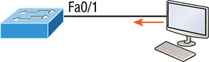
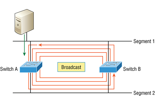
If you want to set up a switch port to allow only one host per port and make sure the port will shut down if this rule is violated, use the following commands like this: These commands are probably the most popular because they prevent random users from connecting to a specific switch or access point in their office. The port security default that’s immediately set on a port when it’s enabled is maximum 1 and violation shutdown. This sounds good, but the drawback is that it only allows a single MAC address to be used on the port. So if anyone, including you, tries to add another host on that segment, the switch port will immediately enter error-disabled state, and the port will turn amber. When that happens, you have to manually go into the switch and re-enable the port by cycling it with a shutdown and then a no shutdown command. Probably one of my favorite commands is the sticky command, and not just because it’s got a cool name. It also makes very cool things happen. You can find this command under the mac-address command: Basically, with the sticky command you can provide static MAC address security without having to type in absolutely everyone’s MAC address on the network. I like things that save me time like that! In the preceding example, the first two MAC addresses coming into the port “stick” to it as static addresses and will be placed in the running-config, but when a third address tried to connect, the port would shut down immediately. Here’s one more example… Figure 7.6 displays a host in a company lobby that needs to be secured against the Ethernet cable used by anyone other than one, authorized individual. Figure 7.6 Protecting a PC in a lobby What can you do to ensure that only the MAC address of the lobby PC is allowed by switch port Fa0/1? The solution is pretty straightforward because in this case, the defaults for port security will work well. All I have left to do is add a static MAC entry: To protect the lobby PC, we would set the maximum allowed MAC addresses to 1 and the violation to restrict so the port doesn’t get shut down every time someone tries to use the Ethernet cable (which would be constantly). By using violation restrict, the unauthorized frames would just be dropped. But did you notice that I enabled port-security and then set a static MAC address? Remember that as soon as you enable port-security on a port, it defaults to violation shutdown and a maximum of 1. So all I needed to do was change the violation mode and add the static MAC address! At a large Fortune 50 company in San Jose, California, there was a PC in the lobby that held the company directory. With no security guard present in the lobby, the Ethernet cable connecting the PC was free game to all vendors, contractors, and visitors waiting in the lobby. Port security to the rescue! When port security was enabled on the port with the switchport port-security command, the switch port connecting to the PC was automatically secured with the defaults of allowing only one MAC address to associate to the port and violation shutdown. However, the port was always going into err-shutdown mode whenever anyone tried to use the Ethernet port. When the violation mode was changed to restrict and a static MAC address was set for the port with the switchport port-security mac-address command, only the Lobby PC was able to connect and communicate on the network! Problem solved! Redundant links between switches are important to have in place because they help prevent network failures in the event that one link stops working. But while it’s true that redundant links can be extremely helpful, they can also cause more problems than they solve! This is because frames can be flooded down all redundant links simultaneously, creating network loops as well as other evils. Here’s a list of some of the ugliest problems that can occur:
Figure 7.7 Broadcast storm Figure 7.8 Multiple frame copies All of these problems spell disaster or close, and they’re all really bad situations that must be avoided or fixed somehow. That’s where the Spanning Tree Protocol comes into play. It was actually developed to solve every one of the problems I just told you about! Now that I explained the issues that can occur when you have redundant links, or when you have links that are improperly implemented, I’m sure you understand how vital it is to prevent them. I’ll be honest here—the best solutions are beyond the scope of this chapter. We’ll get into that territory when we explore the more advanced Cisco exam objectives coming up in Chapter 9. For now, let’s focus on configuring some switching! You get a lot of variety when it comes to Cisco Catalyst switches. Some run 10 Mbps, while others can speed all the way up to 10 Gbps or higher switched ports with a combination of twisted-pair and fiber. These newer switches, like the 3850, also have more intelligence, so they can give you data fast—mixed media services, too! Coming up, I’m going to show you how to start up and configure a Cisco Catalyst switch using the command-line interface (CLI). After you get the basic commands down in this chapter, you’ll learn to configure virtual LANs (VLANs), plus Inter-Switch Link (ISL) and 802.1q trunking in the next one. Here’s a list of the basic tasks we’ll be covering next:
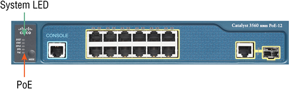
Before we actually get into configuring one of the Catalyst switches, I want you to be familiar with the boot process of these switches. Figure 7.9 shows a typical Cisco
Catalyst switch.
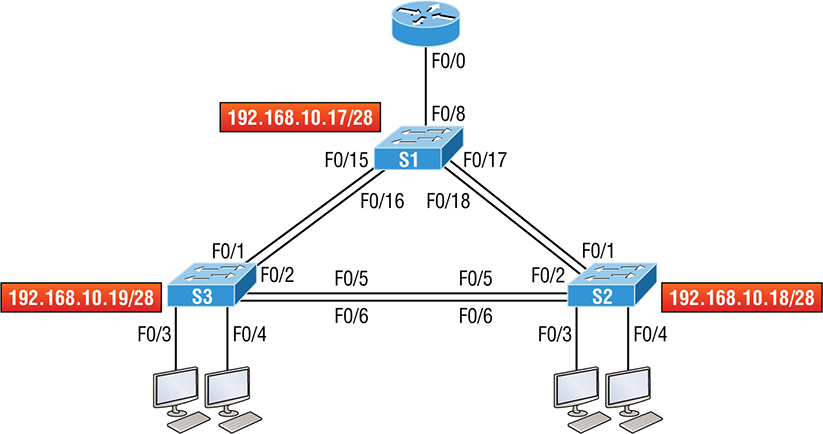
Figure 7.9 A Cisco Catalyst switch The first thing I want to point out is that the console port for Catalyst switches is typically found on the back of the switch. On a smaller switch like the 3560 shown in the figure, the console is right in the front to make it easier to use. The eight-port 2960 looks exactly the same. If the POST completes successfully, the system LED turns green, but if the POST fails, it will turn amber. That amber glow is an ominous thing—typically fatal. So keep a spare switch around, especially in case a production switch dies on you! The bottom button is used to indicate which lights are providing Power over Ethernet (PoE). You can see this by pressing the Mode button. The PoE is a very cool feature because it allows me to power my access point and phone by just connecting them into the switch with an Ethernet cable—sweet. Figure 7.10 shows the switched network we’ll be working on. Figure 7.10 Our switched network You can use any layer 2 switches for this chapter to follow the configuration, but when we get to Chapter 8, you’ll need at least one router plus a layer 3 switch, like my 3560. Now if we connect our switches to each other, as shown in Figure 7.10, first we’ll need a crossover cable between the switches. My 3560 switches autodetect the connection type, so I was able to use straight-through cables—not all switches autodetect the cable type. Different switches have different needs and abilities, so keep this in mind when connecting various switches together. Make a mental note that in the Cisco exam objectives, switches never autodetect! Okay—so when you first connect the switch ports to each other, the link lights are amber and then turn green, indicating normal operation. What you’re actually watching is spanning-tree converging, and this process takes around 50 seconds with no extensions enabled. If you connect into a switch port and the switch port LED is alternating green and amber, it means the port is experiencing errors. When this happens, check the host NIC or the cabling, possibly even the duplex settings on the port to make sure they match the host setting. Absolutely not! Switches have all ports enabled and ready to rock. Take the switch out of the box, plug it in, and the switch starts learning MAC addresses in the CAM. So why would I need an IP address since switches are providing layer 2 services? Because you still need it for in-band management purposes! Telnet, SSH, SNMP, etc., all need an IP address in order to communicate with the switch through the network in-band. Remember, since all ports are enabled by default, you need to shut down unused ports or assign them to an unused VLAN for security reasons. So where do we put this management IP address the switch needs for management purposes? On the predictably named management VLAN interface—a routed interface on every Cisco switch called interface VLAN 1. This management interface can be changed, and Cisco recommends that you do change this to a different management interface for better security. Let’s configure our switches now. We’re going to begin by connecting into each switch and setting the administrative functions. We’ll also assign an IP address to each switch, but as I said, doing that isn’t really necessary to make our network function. The only reason we’re going to do that is so we can manage/administer it remotely, via Telnet for example. Let’s use a simple IP scheme like 192.168.10.16/28. This mask should be familiar to you! Check out the following output: The first thing to notice here is that there’s no IP address configured on the switch’s physical interfaces. Since all ports on a switch are enabled by default, there’s not really a whole lot to configure. The IP address is configured under a logical interface, called a management domain or VLAN. You can use the default VLAN 1 to manage a switched network just as we’re doing here, but you can opt to use a different VLAN for management. The rest of the configuration is basically the same as the process you go through for router configuration. So remember… no IP addresses on physical switch interfaces, no routing protocols, and so on. We’re performing layer 2 switching at this point, not routing! Also, make a note to self that there is no AUX port on Cisco switches. Here is the S2 configuration: We should now be able to ping from S2 to S1. Let’s try it: Okay—now why did I get only four pings to work instead of five? The first period [.] is a time-out, but the exclamation point [!] is a success. It’s a good question, and here’s your answer: the first ping didn’t work because of the time that ARP takes to resolve the IP address to its corresponding hardware MAC address. Check out the S3 switch configuration: Let’s ping to S1 and S2 from the S3 switch and see what happens: In the output of the show ip arp command, the dash (-) in the minutes column means that it is the physical interface of the device. Now, before we move on to verifying the switch configurations, there’s one more command you need to know about, even though we don’t really need it in our current network because we don’t have a router involved yet. It’s the ip default-gateway command. If you want to manage your switches from outside your LAN, you must set a default gateway on the switches just as you would with a host, and you do this from global config. Here’s an example where we introduce our router with an IP address using the last IP address in our subnet range: Now that we have all three switches basically configured, let’s have some fun with them! A secured switch port can associate anywhere from 1 to 8,192 MAC addresses, but the 3560s I am using can support only 6,144, but that’s more than enough. You can choose to allow the switch to learn these values dynamically, or you can set static addresses for each port using the switchport port-security mac-address
mac-address command. So let’s set port security on our S3 switch now. Ports Fa0/3 and Fa0/4 will have only one device connected in our lab. By using port security, we’re assured that no other device can connect once our hosts in ports Fa0/3 and in Fa0/4 are connected. Here’s how to easily do that with just a couple commands: The first command sets the mode of the ports to “access” ports. These ports must be access or trunk ports to enable port security. By using the command switchport port-security on the interface, I’ve enabled port security with a maximum MAC address of 1 and violation of shutdown. These are the defaults, and you can see them in the highlighted output of the show port-security int f0/3 command in the preceding code. Port security is enabled, as displayed on the first line, but the second line shows
Secure-down because I haven’t connected my hosts into the ports yet. Once I do, the status will show Secure-up and would become Secure-shutdown if a violation occurs. I’ve just got to point out this important fact one more time: It’s very important to remember that you can set parameters for port security but it won’t work until you enable port security at the interface level. Notice the output for port F0/6: Port Fa0/6 has been configured with a violation of restrict, but the first line shows that port security has not been enabled on the port yet. Remember, you must use this command at interface level to enable port security on a port: There are two other modes you can use instead of just shutting down the port. The restrict and protect modes mean that another host can connect up to the maximum MAC addresses allowed, but after the maximum has been met, all frames will just be dropped and the port won’t be shut down. Both the restrict and shutdown violation modes alert you via SNMP that a violation has occurred on a port. You can then call the abuser and tell them they’re busted—you can see them, you know what they did last summer and they’re in trouble! If you’ve configured ports with the violation shutdown command, then the ports will look like this when a violation occurs: Here you can see that the port is in Secure-shutdown mode and the light for the port would be amber. To enable the port again, you’d need to do this: Let’s verify our switch configurations before we move onto VLANs in the next chapter. Beware that even though some switches will show err-disabled instead of Secure-shutdown as my switch shows, there is no difference between the two. The first thing I like to do with any router or switch is to run through the configurations with a show running-config command. Why? Because doing this gives me a really great overview of each device. It’s time consuming, and showing you all the configs would take up way too many pages in this book. Besides, we can run other commands that will still stock us up with really good information. For example, to verify the IP address set on a switch, we can use the show interface command. Here’s the output: The previous output shows the interface is in up/up status. Remember to always check this interface, either with this command or the show ip interface brief command. Lots of people tend to forget that this interface is shutdown by default. I’m sure you remember being shown this command earlier in the chapter. Using it displays the forward filter table, also called a content addressable memory (CAM) table. Here’s the output from the S1 switch: The switches use base MAC addresses, which are assigned to the CPU. The first one listed is the base mac address of the switch. From the preceding output, you can see that we have six MAC addresses dynamically assigned to Fa0/1, meaning that port Fa0/1 is connected to another switch. Ports Fa0/5 and Fa0/6 have only one MAC address assigned, and all ports are assigned to VLAN 1. Let’s take a look at the S2 switch CAM and see what we can find out. This output tells us that we have seven MAC addresses assigned to Fa0/5, which is our connection to S3. But where’s port 6? Since port 6 is a redundant link to S3, STP placed Fa0/6 into blocking mode. You can set a static MAC address in the MAC address table, but like setting static MAC port security without the sticky command, it’s a ton of work. Just in case you want to do it, here’s how: On the left side of the output you can see that a static MAC address has now been assigned permanently to interface Fa0/7 and that it’s also been assigned to VLAN 1 only. This chapter offered lots of great information. You’ve learned a lot and just maybe even had a little fun along the way! You’ve configured and verified all switches and set port security, which means you’re ready to learn all about virtual LANs. I’m going to save all our switch configurations so we’ll be able to start right from here in Chapter 8. In this chapter, I talked about the differences between switches and bridges and how they both work at layer 2. They create MAC address forward/filter tables in order to make decisions on whether to forward or flood a frame. Although everything in this chapter is important, I wrote two port-security sections—one to provide a foundation and one with a configuration example. You must know both these sections in detail. I also covered some problems that can occur if you have multiple links between bridges (switches). Finally, we went through a detailed configuration of Cisco’s Catalyst switches, including verifying the configuration itself. Remember the three switch functions. Address learning, forward/filter decisions, and loop avoidance are the functions of a switch. Remember the command show mac address-table. The command show mac address-table will show you the forward/filter table used on the LAN switch. Understand the reason for port security. Port security restricts access to a switch based on MAC addresses. Know the command to enable port security. To enable port security on a port, you must first make sure the port is an access port with switchport mode access and then use the switchport port-security command at the interface level. You can set the port security parameters before or after enabling port security. Know the commands to verify port security. To verify port security, use the show port-security, show port-security interface
interface, and show running-config commands. You can find the answers to these questions in the Appendix. Which of the following statements is not true with regard to layer 2 switching?
What statement(s) is/are true about the output shown here? (Choose all that apply.)
Which of the following commands in this configuration is a prerequisite for the other commands to function?
Which if the following is not an issue addressed by STP?
Which two of the following switch port violation modes will alert you via SNMP that a violation has occurred on a port?
On which default interface have you configured an IP address for a switch?
Which Cisco IOS command is used to verify the port security configuration of a
switch port?
Which of the following methods will ensure that only one specific host can connect to port Fa0/3 on a switch? (Choose two. Each correct answer is a separate solution.)
What will be the effect of executing the following command on port F0/1?
The conference room has a switch port available for use by the presenter during classes, and each presenter uses the same PC attached to the port. You would like to prevent other PCs from using that port. You have completely removed the former configuration in order to start anew. Which of the following steps is not required to prevent any other PCs from using that port?
![]() 1.13 Describe switching concepts
1.13 Describe switching concepts
![]() 5.7 Configure Layer 2 security features (DHCP snooping, dynamic ARP inspection, and port security)
5.7 Configure Layer 2 security features (DHCP snooping, dynamic ARP inspection, and port security) When Cisco brings up switching in the Cisco exam objectives, they mean layer 2 switching unless they say otherwise. Layer 2 switching is the process of using the hardware address of devices on a LAN to segment a network. So, in this chapter, we’re going to cover the finer points of layer 2 switching to make sure you know exactly how it works.
![]() To find your included bonus material, as well as Todd Lammle videos, practice questions & hands-on labs, please see www.lammle.com/ccna
To find your included bonus material, as well as Todd Lammle videos, practice questions & hands-on labs, please see www.lammle.com/ccnaSwitching Services
Three Switch Functions at Layer 2
Address Learning
Forward/Filter Decisions
Switch#sh mac address-table

Vlan Mac Address Type Ports]]> ---- ----------- -------- -----
1 0005.dccb.d74b DYNAMIC Fa0/1
1 000a.f467.9e80 DYNAMIC Fa0/3
1 000a.f467.9e8b DYNAMIC Fa0/4
1 000a.f467.9e8c DYNAMIC Fa0/3
1 0010.7b7f.c2b0 DYNAMIC Fa0/3
1 0030.80dc.460b DYNAMIC Fa0/3
1 0030.9492.a5dd DYNAMIC Fa0/1
1 00d0.58ad.05f4 DYNAMIC Fa0/1
Port Security
Switch#config t
Switch(config)#int f0/1
Switch(config-if)#switchport mode access
Switch(config-if)#switchport port-security
Switch(config-if)#switchport port-security ?
aging Port-security aging commands
mac-address Secure mac address
maximum Max secure addresses
violation Security violation mode
<cr>
Switch(config-if)#switchport port-security maximum 1

Switch(config-if)#switchport port-security violation shutdown
Switch(config-if)#switchport port-security mac-address sticky
Switch(config-if)#switchport port-security maximum 2
Switch(config-if)#switchport port-security violation shutdown
Switch(config-if)#switchport port-security
Switch(config-if)#switchport port-security violation restrict
Switch(config-if)#switchport port-security mac-address aa.bb.cc.dd.ee.ff
![]()
Lobby PC Always Being Disconnected Becomes a Security RiskLoop Avoidance
Configuring Catalyst Switches
![]() You can learn all about the Cisco family of Catalyst switches at
https://www.cisco.com/c/en/us/products/switches/index.html
You can learn all about the Cisco family of Catalyst switches at
https://www.cisco.com/c/en/us/products/switches/index.htmlCatalyst Switch Configuration
Do We Need to Put an IP Address on a Switch?
S1
Switch>en
Switch#config t
Switch(config)#hostname S1
S1(config)#enable secret todd
S1(config)#int f0/15
S1(config-if)#description 1st connection to S3
S1(config-if)#int f0/16
S1(config-if)#description 2nd connection to S3
S1(config-if)#int f0/17
S1(config-if)#description 1st connection to S2
S1(config-if)#int f0/18
S1(config-if)#description 2nd connection to S2
S1(config-if)#int f0/8
S1(config-if)#desc Connection to IVR
S1(config-if)#line con 0
S1(config-line)#password console
S1(config-line)#login
S1(config-line)#line vty 0 15
S1(config-line)#password telnet
S1(config-line)#login
S1(config-line)#int vlan 1
S1(config-if)#ip address 192.168.10.17 255.255.255.240
S1(config-if)#no shut
S1(config-if)#exit
S1(config)#banner motd #this is my S1 switch#
S1(config)#exit
S1#copy run start
Destination filename [startup-config]? [enter]
Building configuration...
[OK]
S1#
S2
Switch#config t
Switch(config)#hostname S2
S2(config)#enable secret todd
S2(config)#int f0/1
S2(config-if)#desc 1st connection to S1
S2(config-if)#int f0/2
S2(config-if)#desc 2nd connection to s1
S2(config-if)#int f0/5
S2(config-if)#desc 1st connection to S3
S2(config-if)#int f0/6
S2(config-if)#desc 2nd connection to s3
S2(config-if)#line con 0
S2(config-line)#password console
S2(config-line)#login
S2(config-line)#line vty 0 15
S2(config-line)#password telnet
S2(config-line)#login
S2(config-line)#int vlan 1
S2(config-if)#ip address 192.168.10.18 255.255.255.240
S2(config)#exit
S2#copy run start
Destination filename [startup-config]?[enter]
Building configuration...
[OK]
S2#
S2#ping 192.168.10.17
Type escape sequence to abort.
Sending 5, 100-byte ICMP Echos to 192.168.10.17, timeout is 2 seconds:
.!!!!
Success rate is 80 percent (4/5), round-trip min/avg/max = 1/1/1 ms
S2#
S3
Switch>en
Switch#config t
SW-3(config)#hostname S3
S3(config)#enable secret todd
S3(config)#int f0/1
S3(config-if)#desc 1st connection to S1
S3(config-if)#int f0/2
S3(config-if)#desc 2nd connection to S1
S3(config-if)#int f0/5
S3(config-if)#desc 1st connection to S2
S3(config-if)#int f0/6
S3(config-if)#desc 2nd connection to S2
S3(config-if)#line con 0
S3(config-line)#password console
S3(config-line)#login
S3(config-line)#line vty 0 15
S3(config-line)#password telnet
S3(config-line)#login
S3(config-line)#int vlan 1
S3(config-if)#ip address 192.168.10.19 255.255.255.240
S3(config-if)#no shut
S3(config-if)#banner motd #This is the S3 switch#
S3(config)#exit
S3#copy run start
Destination filename [startup-config]?[enter]
Building configuration...
[OK]
S3#
S3#ping 192.168.10.17
Type escape sequence to abort.
Sending 5, 100-byte ICMP Echos to 192.168.10.17, timeout is 2 seconds:
.!!!!
Success rate is 80 percent (4/5), round-trip min/avg/max = 1/3/9 ms
S3#ping 192.168.10.18
Type escape sequence to abort.
Sending 5, 100-byte ICMP Echos to 192.168.10.18, timeout is 2 seconds:
.!!!!
Success rate is 80 percent (4/5), round-trip min/avg/max = 1/3/9 ms
S3#sh ip arp
Protocol Address Age (min) Hardware Addr Type Interface
Internet 192.168.10.17 0 001c.575e.c8c0 ARPA Vlan1
Internet 192.168.10.18 0 b414.89d9.18c0 ARPA Vlan1
Internet 192.168.10.19 - ecc8.8202.82c0 ARPA Vlan1
S3#
S3#config t
S3(config)#ip default-gateway 192.168.10.30
Port Security
S3#config t
S3(config)#int range f0/3-4
S3(config-if-range)#switchport mode access
S3(config-if-range)#switchport port-security
S3(config-if-range)#do show port-security int f0/3
Port Security : Enabled
Port Status : Secure-down
Violation Mode : Shutdown
Aging Time : 0 mins
Aging Type : Absolute
SecureStatic Address Aging : DisabledMaximum MAC Addresses : 1
Total MAC Addresses : 0
Configured MAC Addresses : 0
Sticky MAC Addresses : 0
Last Source Address:Vlan : 0000.0000.0000:0
Security Violation Count : 0
S3#config t
S3(config)#int range f0/6
S3(config-if-range)#switchport mode access
S3(config-if-range)#switchport port-security violation restrict
S3(config-if-range)#do show port-security int f0/6
Port Security : Disabled
Port Status : Secure-up
Violation Mode : restrict
[output cut]
S3(config-if-range)#switchport port-security
S3#sh port-security int f0/3
Port Security : EnabledPort Status : Secure-shutdown
Violation Mode : Shutdown
Aging Time : 0 mins
Aging Type : Absolute
SecureStatic Address Aging : Disabled
Maximum MAC Addresses : 1
Total MAC Addresses : 2
Configured MAC Addresses : 0
Sticky MAC Addresses : 0
Last Source Address:Vlan : 0013:0ca69:00bb3:00ba8:1
Security Violation Count : 1
S3(config-if)#shutdown
S3(config-if)#no shutdown
Verifying Cisco Catalyst Switches
S3#sh int vlan 1
Vlan1 is up, line protocol is up
Hardware is EtherSVI, address is ecc8.8202.82c0 (bia ecc8.8202.82c0)
Internet address is 192.168.10.19/28
MTU 1500 bytes, BW 1000000 Kbit/sec, DLY 10 usec,
reliability 255/255, txload 1/255, rxload 1/255
Encapsulation ARPA, loopback not set
[output cut]
![]() Never forget that IP addresses aren’t needed on a switch for it to operate. The only reason we would set an IP address, mask, and default gateway is for management purposes.
Never forget that IP addresses aren’t needed on a switch for it to operate. The only reason we would set an IP address, mask, and default gateway is for management purposes.show mac address-table
S3#sh mac address-table
Mac Address Table]]> -------------------------------------------
Vlan Mac Address Type Ports]]> ---- ----------- -------- -----
All 0100.0ccc.cccc STATIC CPU
[output cut]
1 000e.83b2.e34b DYNAMIC Fa0/1
1 0011.1191.556f DYNAMIC Fa0/1
1 0011.3206.25cb DYNAMIC Fa0/1
1 001a.2f55.c9e8 DYNAMIC Fa0/1
1 001a.4d55.2f7e DYNAMIC Fa0/1
1 001c.575e.c891 DYNAMIC Fa0/1
1 b414.89d9.1886 DYNAMIC Fa0/5
1 b414.89d9.1887 DYNAMIC Fa0/6
S2#sh mac address-table
Mac Address Table]]> -------------------------------------------
Vlan Mac Address Type Ports]]> ---- ----------- -------- -----
All 0100.0ccc.cccc STATIC CPU
[output cut
1 000e.83b2.e34b DYNAMIC Fa0/5
1 0011.1191.556f DYNAMIC Fa0/5
1 0011.3206.25cb DYNAMIC Fa0/5
1 001a.4d55.2f7e DYNAMIC Fa0/5
1 581f.aaff.86b8 DYNAMIC Fa0/5
1 ecc8.8202.8286 DYNAMIC Fa0/5
1 ecc8.8202.82c0 DYNAMIC Fa0/5
Total Mac Addresses for this criterion: 27
S2#
Assigning Static MAC Addresses
S3(config)#mac address-table ?
aging-time Set MAC address table entry maximum age
learning Enable MAC table learning feature
move Move keyword
notification Enable/Disable MAC Notification on the switch
static static keyword
S3(config)#mac address-table static aaaa.bbbb.cccc vlan 1 int fa0/7
S3(config)#do show mac address-table
Mac Address Table]]> -------------------------------------------
Vlan Mac Address Type Ports]]> ---- ----------- -------- -----
All 0100.0ccc.cccc STATIC CPU
[output cut]
1 000e.83b2.e34b DYNAMIC Fa0/1
1 0011.1191.556f DYNAMIC Fa0/1
1 0011.3206.25cb DYNAMIC Fa0/1
1 001a.4d55.2f7e DYNAMIC Fa0/1
1 001b.d40a.0538 DYNAMIC Fa0/1
1 001c.575e.c891 DYNAMIC Fa0/1
1 aaaa.bbbb.0ccc STATIC Fa0/7
[output cut]
Total Mac Addresses for this criterion: 59
Summary
Exam Essentials
Review Questions