CHAPTER 18
Troubleshooting IP, IPv6, and VLANs
The following CCNA exam topics are covered in this chapter: 1.0 Network Fundamentals 2.0 Network Access
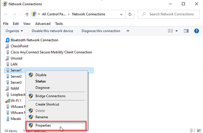
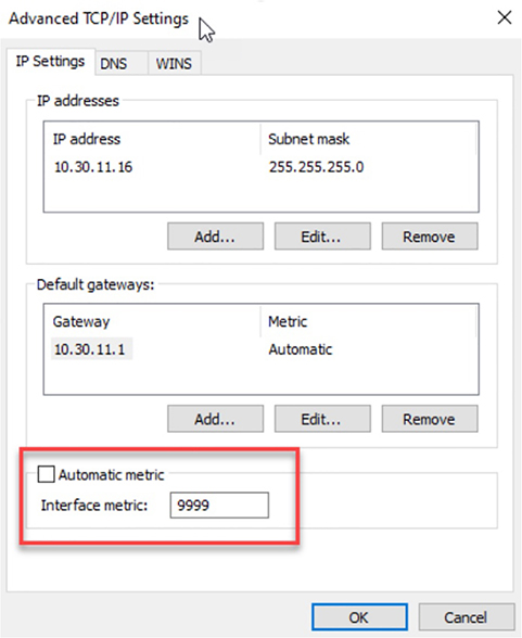
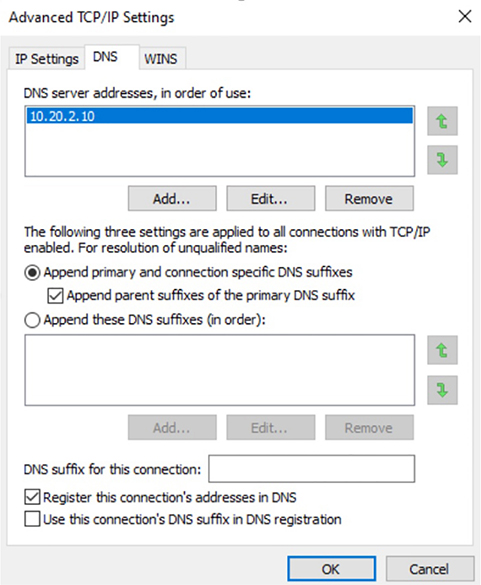
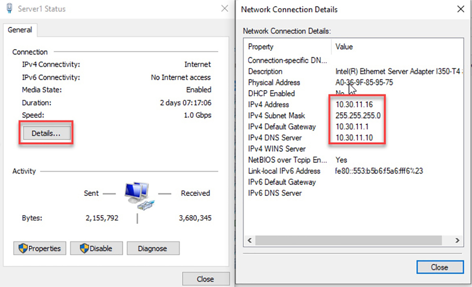
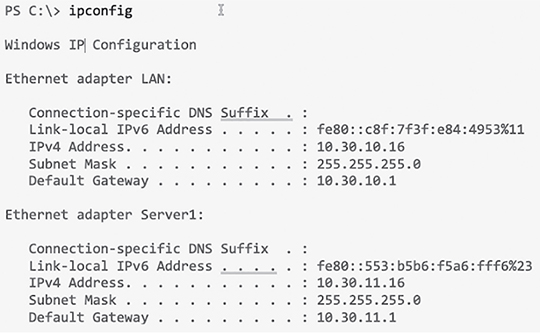
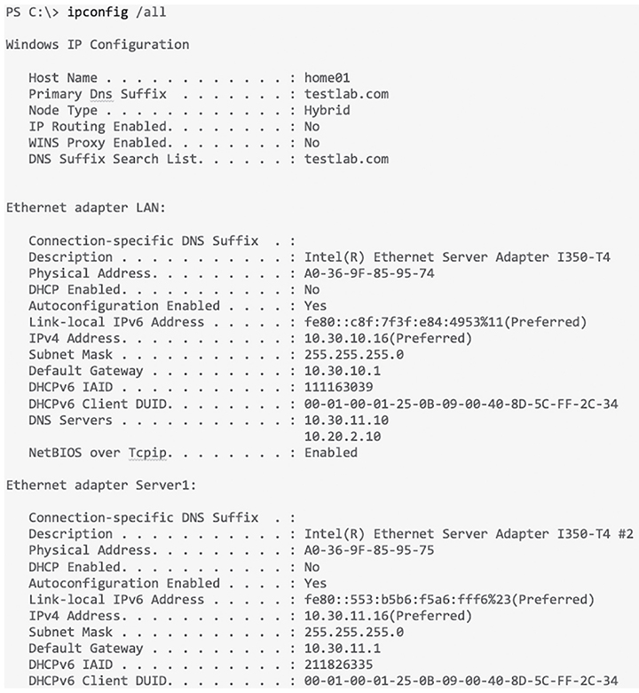
Although it’s hard to predict exactly what the CCNA exam will throw at you, I’ll use carefully planned scenarios to guide you through Cisco’s troubleshooting steps. With the skills you’ll gain pushing through the scenarios, you’ll be able to successfully solve the problems you’re likely to face on the exam and in the real world. This chapter is specifically designed to solidify your troubleshooting foundation, so let’s get started! Let’s get started by looking at the components we’re going to connect to our network and find out how to quickly get them online for testing in the lab or workplace. An endpoint is basically just something that connects to the network through a wired or wireless connection. Most vendors license based upon how many active endpoints on the network are using the service the product provides. I’ll quickly cover some common endpoints now. Desktops and Laptops are by far the most prevalent kind of endpoint in our networks because pretty much every employee has at least one of these assigned to them. Most companies are either on Microsoft Windows 10 or in process of upgrading to it from Windows 7. Some also have a few Apple Mac computers in the mix, but you usually won’t find Linux on the end user side of things. And of course, all computers can use wired or wireless connections interchangeably. It’s also pretty common for staff to be issued a mobile phone and/or a tablet that will often connect to a SSID provided by the office. Most companies also allow employees to use their own devices on the network, but access is usually restricted via security policies. Typical mobile devices would be Apple iPhone/iPad or some Android variant, which all tend to use wireless connections exclusively. Even though these devices are actually there to provide wireless access to your endpoints, they connect to the network too, so they’re also considered endpoints. Access Points typically use wired connections for power supply and to get on the network, but they can also use wireless connections in more advanced configurations. Most companies either have a Voice over IP (VoIP) solution or they’re talking about it. Because of this, phones hog lots of switch ports, so to save on cabling requirements, office computers are often connected to the IP Phone’s built-in switch. That way, it’s only the phone that gets connected to the access switch. IP Phones typically use wired ethernet connections for power rather than plugging into the wall. With the genesis of the IoT, everything from light bulbs to fridges and alarm systems are all the network now and they’re all endpoints too! Just like your server at a restaurant, the server on the network delivers what you’ve ordered. Servers are basically higher end computers used to provide infrastructure or application services to users and they tend to come in these three forms: Tower Tower end servers are pretty much just standard computer towers that can provide a few more resources than a regular computer. Rack Server The most common type of server is a rack-mounted simple server that’s usually one rack unit (RU) in size but can be bigger. People sometimes call rack servers pizza boxes because they’re often large squares. Blade Server This is the most complex type of server, which is actually a blade that connects into a large chassis. These systems are designed to be very redundant and resilient. There are way too many different server roles out there for me to talk about all of them in this chapter, but here’s list the most common kinds of servers found in a network: Active Directory Microsoft AD is Windows Server’s flagship role for User and Computer management and it’s used one way or another by almost every company in existence! DNS Using the Internet in any kind of efficient way depends on DNS because without it, we would all be surfing by memorizing IP addresses. DHCP Covered earlier, DHCP is how your endpoints dynamically learn their IP address to get on the network. Hypervisor I’ll talk about this role more when we get into virtualization, but for now, just know it’s what allows us to run virtual machines. RADIUS This role is largely used by wireless to authenticate connections into the network. TACACS+ This role is used for device administration and can control what a user has access to when they log into a device. Email The type of server that manages sending and receiving email messages. File File servers store a large number of files for users to access. Databases These servers store data in mysterious tables ran by crazy wizards known as DBAs. Avoid DBAs at all cost! Web This type of server runs the webpages we browse on the Internet. It’s a fact that at some point in your Cisco studies, you’ll need to know how to verify and change the IP address on the operating system you’re using. Doing this is really helpful for labs that use PCs for testing since you can adjust the IP to suit your lab environment. Clearly, being good at this is vital in the real world because most servers use static IP addresses—not every subnet will have DHCP running and you’ll probably need to troubleshoot an end user’s connection from time to time. On Windows operating systems you can set the IP address from Network Connections. The easiest way to get there is to type ncpa.cpl in the search bar or from the Run command. You can also get there through the Control panel by selecting Network and Sharing Center then Change adapter settings. Once you’re in, just right-click the network adapter you want to set the IP on and then left-click on properties as shown in Figure 18.1. Figure 18.1 Network Connections page The properties page has a bunch of protocol information that we can adjust for the network adapter. For now, I’m going to choose Internet Protocol Version 4 (TCP/IP) and I’m going to click on properties as pictured in Figure 18.2. Figure 18.2 IPv4 Properties Page On the next page, I can finally set my IP address information including the IP address, subnet mask, and the default gateway the network adapter will use. And because I’m statically setting an IP address, I’ve also got to statically set the DNS address used to resolve domain names too since the network adapter won’t be learning it via DHCP (See Figure 18.3.). Figure 18.3 Setting the IP and DNS addresses Now that the network adapter’s IP and DNS is set, I could just hit OK to apply the changes. But I’m not going to do that just yet because I want to introduce you to a couple of important items under the Advanced button first. This is where you can add additional IP addresses under the interface. This is like adding a secondary IP address on a Cisco router interface where you can add as many additional IPs as you want. Check out Figure 18.4. This comes in really handy for web servers where each web site may want to bind to a different IP address on the system. Like a Cisco router, Windows also has a routing table. So if you have multiple active interfaces on your computer, you can choose to adjust the interface metric, making it either more or less desirable when the computer needs to pick an interface to route traffic out of. Figure 18.4 Advanced tab The last thing I want to point out here in these properties is the DNS tab. This is where you can choose to add more DNS servers if you have more than two, as shown in Figure 18.5. Figure 18.5 DNS tab Oh—and I can also choose to append domain names to my DNS queries! If I add testlab.com I just need to type web01 to reach web01.testlab.com because it will append the name for me—cool. So with all that out of the way, I’ll hit OK on all the dialogs until I’m back to Network Connections screen. And if I want to verify the IP change from Network Connections, I’ll just double-click the network adapter and then click Details. From there, I can see the IP information pictured in Figure 18.6. Figure 18.6 Verifying IP information Good to know is that you can also use the ipconfig command to get the IP address information from Windows’s command prompt. This will give you the IP address, subnet mask and default gateway for each interface as shown in Figure 18.7. Figure 18.7 IPconfig And if you want to check out information like DNS servers as well, just go with the ipconfig /all command to see all information about the network adapters on the system
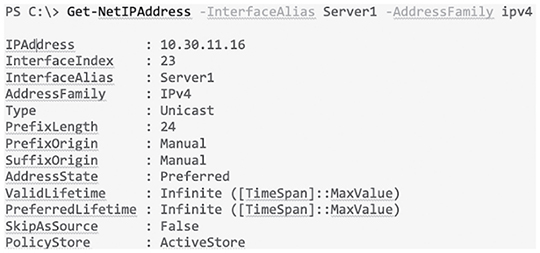
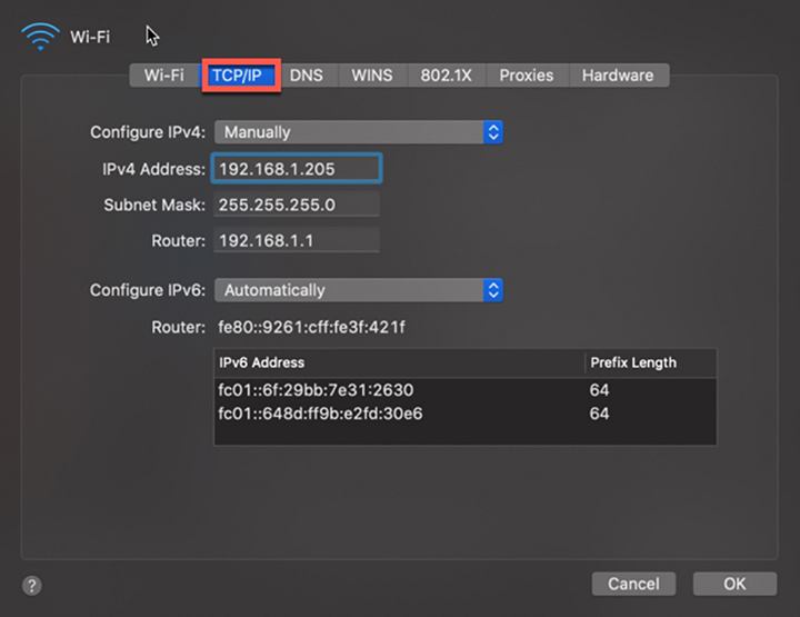
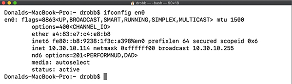
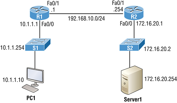
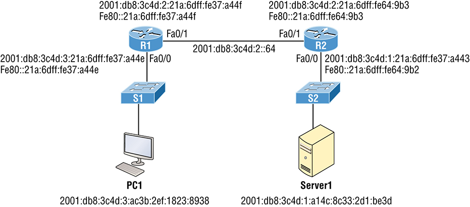
(See Figure 18.8.). Figure 18.8 IPConfig /all Okay—so you know that the ipconfig method works fine, but it’s an older command. The new way to do things in Microsoft products is to use powershell instead of CMD. The main advantage to this is that you can filter the output you get back instead of getting all the network adapters every time you type ipconfig. In powershell, I can use the Get-NetIPAddress cmdlet to get the IP address and netmask and I can also opt to just see my Server1 interface and only IPv4 addresses (See Figure 18.9.). Figure 18.9 Powershell Just understand that this won’t return any default gateway or DNS information because powershell likes to keep its commands very focused. So, I would need to use the Get-DnsClientServerAddress command to get DNS information, and Get-NetRoute to see routing information. To verify IP information on a Mac, open Network Preferences by either clicking the Wireless signal on the top right of the desktop or by opening System Preferences and selecting it from there (See Figure 18.10.). Figure 18.10 MAC OS From there, you can see the IP address by choosing the network you’re connected to. You won’t see any other information unless you click on Advanced and once you, you’ll get the screen shown in Figure 18.11. Under the TCP/IP tab, I can set the IP address, subnet mask, and gateway. Figure 18.11 MAC TCP/IP Screen Under the DNS tab shown in Figure 18.12, I can add DNS servers, which appends domain names to DNS queries just like in Windows. Figure 18.12 MAC DNS tab Now if I want to verify the IP information from CLI, I’ll use the ifconfig command, which can also be used to set an IP address. Just know that the static IP won’t survive a reboot. Check out Figure 18.13. Figure 18.13 MAC ifconfig Both Ubuntu and Redhat based Linux desktops actually go through the same steps to change an IP address via the GUI. They only differ in how you change the IP address in the Linux shell. To verify or change the IP address in Ubuntu or Fedora/Centos, open Settings and then Network. You can also click the network on the top right of the screen and then select the connection’s settings as shown in Figure 18.14. Figure 18.14 Ubuntu IP Settings From there, click the gear icon to see the network information on the Linux box show in Figure 18.15. This is where you can adjust the IP address, subnet mask, default gateway, and the DNS servers. Figure 18.15 the Linux gear icon When you’re done, just hit the Apply button to make the changes active. Finally, to verify the IP address, use the ifconfig command, just like we did on the Mac OS example. Let’s begin troubleshooting now with a short, sweet review of IP routing. When a host wants to transmit a packet, IP looks at the destination address to determine if it’s a local or remote request. If it’s local, IP just broadcasts a frame over the local network to find the host using an ARP request. If it’s a remote request, the host will send out an ARP request to the default gateway to discover the MAC address of the router. Once the hosts have the default gateway address, they’ll send each other a packet to then be transmitted to the Data Link layer for framing. The newly framed packets are then sent out on the local collision domain. The router will receive the frame and remove the packet, and IP will parse the routing table looking for the exit interface on the router. If the destination is found in the routing table, it will packet-switch the packet to the exit interface. At this point, the packet will be framed with new source and destination MAC addresses. With that in mind, what would you say to someone claiming they weren’t able to get to a server on a remote network? Other than reboot Windows, what’s the first thing you would have this user do, or do yourself, to test network connectivity? If you came up with using the Ping program, that’s a great start because Ping is a helpful tool to find out if a host is alive on the network via a simple ICMP echo request and reply. But being able to ping the host as well as the server still doesn’t guarantee that all is well in the network. There’s more to the Ping program than just using it as a quick testing protocol. To be prepared for the exam objectives, get used to connecting to various routers and pinging from them. Of course, pinging from a router is not as good as pinging from the host reporting the problem, but that doesn’t mean we can’t isolate problems from the routers themselves. Let’s use Figure 18.16 as a basis to run through some troubleshooting scenarios. Figure 18.16 Troubleshooting scenario In this first scenario, a manager contacts you saying that he can’t log in to Server1 from PC1. Your job is to find out why and fix it. The Cisco objectives are clear on the troubleshooting steps to take when a problem has been reported, and here they are:
To effectively troubleshoot this problem, we’ll narrow down the possibilities by process of elimination. We’ll start with PC1 and verify that it’s configured correctly and also that IP is working correctly. There are four steps for checking the PC1 configuration:
Let’s check out the PC1 configuration by using the ipconfig command, or ifconfig on a Mac or Linux device: We can also check the route table on the host with the route print command to see if it knows the default gateway: Between the output of the ipconfig command and the route print command, we can rest assured that the hosts are aware of the correct default gateway. Let’s verify that the local IP stack is initialized by pinging the loopback address: This first output confirms the IP address and configured default gateway of the host. Then I verified the fact that the local IP stack is working. Our next move is to verify that the IP stack is talking to the LAN driver by pinging the local IP address: And now that we know the local stack is solid and the IP stack is communicating to the LAN driver, it’s time to check our local LAN connectivity by pinging the default gateway: Looking good! I’d say our host is in good shape. Let’s try to ping the remote server next to see if our host is actually getting off the local LAN to communicate remotely: Well, looks like we’ve confirmed local connectivity but not remote connectivity, so we’re going to have to dig deeper to isolate the problem. But first, and just as important, it’s key to make note of what we can rule out at this point:
Let’s see if we can narrow the problem down further using the traceroute command: Well, we didn’t get beyond our default gateway, so let’s go over to R2 and see if we can talk locally to the server: Okay—we just eliminated a local LAN problem by connecting to Server1 from the R2 router, so we’re good there. Let’s summarize what we know so far:
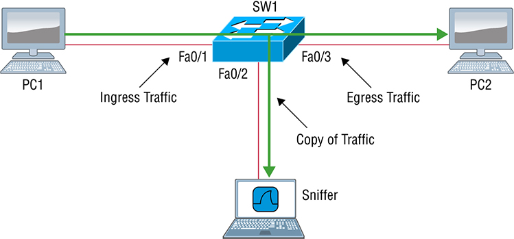
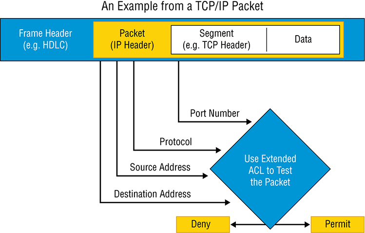
But something is still clearly wrong, so what do we check next? Now would be a great time to verify the Server1 IP configuration and make sure the default gateway is configured correctly. Let’s take a look: The Server1 configuration looks good and the R2 router can ping the server, so it seems that the server’s local LAN is solid, the local switch is working, and there are no cable or interface issues. But let’s zoom in on interface Fa0/0 on R2 and talk about what to expect if there were errors on this interface: You’ve got to be able to analyze interface statistics to find problems there if they exist, so let’s pick out the important factors relevant to achieving that goal next. Speed and duplex settings Good to know that the most common cause of interface errors is a mismatched duplex mode between two ends of an Ethernet link. This is why it’s so important to make sure that the switch and its hosts (PCs, router interfaces, etc.) have the same speed setting. If not, they just won’t connect. Worse, if they do have mismatched duplex settings, you’ll receive a legion of errors, which will cause nasty performance issues, intermittent connectivity—even loss of communication! Using autonegotiation for speed and duplex is a common practice that’s enabled by default. But if this fails for some reason, you’ll have to set the configuration manually like this: If you have a duplex mismatch, a telling sign is that the late collision counter will increment. Input queue drops If the input queue drops counter increments, it signifies that more traffic is being delivered to the router than it can process. If this is consistently high, try to determine exactly when these counters are increasing and how the events relate to CPU usage. You’ll see the ignored and throttle counters increment as well. Output queue drops This counter indicates that packets were dropped due to interface congestion, leading to packet drops and queuing delays. When this occurs, applications like VoIP will experience performance issues. If you observe this constantly incrementing, consider QoS. Input errors Input errors often indicate high errors like CRCs, which can point to cabling problems, hardware issues, or duplex mismatches. Output errors This is the total number of frames that the port tried to transmit when an issue such as a collision occurred. We’re going to move on in our troubleshooting process of elimination by analyzing the routers’ actual configurations. Here’s R1’s routing table: This actually looks pretty good! Both of our directly connected networks are in the table and we can confirm that we have a default route going to the R2 router. So now let’s verify the connectivity to R2 from R1: This looks great too! Our interfaces are correctly configured with the right IP address and the Physical and Data Link layers are up. By the way, I also tested layer 3 connectivity by pinging the R2 Fa0/1 interface. Since everything looks good so far, our next step is to check into the status of R2’s interfaces: Well, everything still checks out at this point. The IP addresses are correct and the Physical and Data Link layers are up. I also tested layer 3 connectivity with a ping to R1, so we’re all good so far. We’ll examine the routing table next: Okay—we can see that all our local interfaces are in the table, as well as a static route to the 10.1.1.0 network. But do you see the problem? Look closely at the static route. The route was entered with an exit interface of Fa0/0, and the path to the 10.1.1.0 network is out Fa0/1! Aha! We’ve found our problem! Let’s fix R2: That should do it. Let’s verify from PC1: Our snag appears to be solved, but just to make sure, we really need to verify with a higher-level protocol like Telnet: Okay, that’s not good! We can ping to the Server1, but we can’t telnet to it. In the past, I’ve verified that telnetting to this server worked, but it’s still possible that we have a failure on the server side. To find out, let’s verify our network first, starting at R1: This is some pretty ominous output! Let’s try from R2 and see what happens: Oh my—I can ping the server from a remote network, but I can’t telnet to it, yet the local router R2 can! These factors eliminate the server being a problem since I can telnet to the server when I’m on the local LAN. And we know we don’t have a routing problem because we fixed that already. So what’s next? Let’s check to see if there’s an ACL on R2: Seriously? What a loopy access list to have on a router! This ridiculous list permits ICMP, but that’s it. It denies everything except ICMP due to the implicit deny ip any any at the end of every ACL. But before we uncork the champagne, we need to see if this foolish list has been applied to our interfaces on R2 to confirm that this is really our problem: There it is—that’s our problem all right! In case you’re wondering why R2 could telnet to Server1, it’s because an ACL filters only packets trying to go through the router—not packets generated at the router. Let’s get to work and fix this: I just verified that I can telnet from PC1 to Server1, but let’s try telnetting from R1 again: Nice—looks like we’re set, but what about using the name? Well, we’re not all set just yet. Let’s fix R1 so that it can provide name resolution: Great—things are looking good from the router, but if the customer can’t telnet to the remote host using the name, we’ve got to check the DNS server to confirm connectivity and for the correct entry to the server. Another option would be to configure the local host table manually on PC1. The last thing to do is to check the server to see if it’s responding to HTTP requests via the telnet command, believe it or not! Here’s an example: Yes—finally! Server1 is responding to requests on port 80, so we’re in the clear. A traffic sniffer can be a valuable tool for monitoring and troubleshooting your network. However, since the inception of switches into our networks more than 20 years ago, troubleshooting has become tougher because we can’t just plug an analyzer into a switch port and be able to read all the network traffic. Before we had switches, we used hubs, and when a hub received a digital signal on one port, the hub sent that digital signal out on all ports except the port it was received on. This allows a traffic sniffer that’s connected to a hub port to receive all traffic in the network. Modern local networks are essentially switched networks. After a switch boots, it starts to build up a layer 2 forwarding table based on the source MAC addresses of the different packets that the switch receives. After the switch builds this forwarding table, it forwards traffic destined for a known MAC address directly to the exit port associated with that MAC address. By default, this prevents a traffic sniffer connected to another port from receiving the unicast traffic. The SPAN feature was introduced on switches to help solve this problem, as shown in Figure 18.17. Figure 18.17 Using SPAN for troubleshooting SPAN helps us analyze network traffic passing through the port by sending a copy of the traffic to another port on the switch that’s been connected to a network analyzer or other monitoring device. SPAN copies the traffic that the device receives and/or sends on source ports to a destination port for analysis. For example, if you would like to analyze the traffic flowing from PC1 to PC2, shown in Figure 18.17, you need to specify a source port where you want to capture the data. You can either configure the interface Fa0/1 to capture the ingress traffic or configure the interface Fa0/3 to capture the egress traffic—your choice. Next, specify the destination port interface where the sniffer is connected and will capture the data, in this example, Fa0/2. The traffic flowing from PC1 to PC2 will then be copied to that interface and you’ll be able to analyze it with a traffic sniffer. Step 1: Associate a SPAN session number with the source port of what you want to monitor. Step 2: Associate a SPAN session number of the sniffer with the destination interface. Step 3: Verify that the SPAN session has been configured correctly. Now connect up your network analyzer into port F0/2 and enjoy! Even though I went through some very basic troubleshooting with ACLs earlier in this chapter, let’s dig a little deeper to make sure you really understand extended named ACLs before hitting IPv6. As you know, standard access lists focus only on IP or IPv6 source addresses. Extended ACLs, however, filter based on the source and destination layer 3 addresses at a minimum. In addition, they can filter using the protocol field in the IP header (Next Header field in IPv6), as well as the source and destination port numbers at layer 4, all shown in Figure 18.18 Figure 18.18 Extended ACLs Using the network layout in Figure 18.16, let’s create an extended named ACL that blocks Telnet to the 172.16.20.254 server from 10.1.1.10. It’s an extended list, so we’ll place it closest to the source address as possible. Step 1: Test that you can telnet to the remote host. Okay, great! Step 2: Create an ACL on R1 that prevents telnetting to the remote host of 172.16.20.254. Using a named ACL, start with the protocol (IP or IPv6), choose either a standard or extended list, and then name it. The name is absolutely case sensitive when applying to an interface. Step 3: Once you’ve created the named list, add your test parameters: Step 4: Verify your access list: Notice the numbers 10 and 20 on the left side of each test statement. These are called sequence numbers and we can use them to edit a single line, delete it, or even add a new line in between two sequence numbers. Named ACLs can be edited; numbered ACLs can’t! Step 5: Configure your ACL on your router interface. Since we’re adding this to the R1 router in Figure 18.16, we’ll add it inbound to interface FastEthernet 0/0, stopping traffic closest to the source: Step 6: Test your access list: Hmm… that didn’t work because I’m still able to telnet to the remote host. Let’s take a look at our list, verify our interface and fix the problem. By verifying the IP addresses in the deny statement in line sequence 10, you can see that my source address is 10.1.1.1 It should have been 10.1.1.10. Step 7: Fix and/or edit your access list. Delete the bad line and reconfigure the ACL to the correct IP: Verify that your list is working: Step 8: Display the ACL again and check the updated hit counters with each line. Also verify that the interface is set with the ACL: The interface was up and working, so verifying at this point was a little overkill. Know that you must be able to look at an interface and troubleshoot issues, such as ACLs set on an interface and be sure to remember the show ip interface command! Next, let’s mix things up a little by adding IPv6 to our network and work through the same troubleshooting steps. I’m going to be straight with you: There isn’t a lot that’s going to be much different regarding IPv6 and the process you just went through in the IPv4 troubleshooting steps. Except the addressing, of course! So other than that key factor, we’ll take the same approach. Using Figure 18.19 specifically because I really want to highlight the differences associated with IPv6. So the problem scenario I’m going to use will also stay the same: PC1 cannot communicate to Server1. I want to point out that this is not an “Introduction to IPv6” chapter, so I’m assuming you’ve got some IPv6 fundamentals down. Figure 18.19 IPv6 troubleshooting scenario Notice that I documented both the link-local and global addresses assigned to each router interface in Figure 18.19. We need both in order to troubleshoot, so right away, you can see that things get a bit more complicated because of the longer addresses and the fact that there are multiple addresses per interface involved! But before we start troubleshooting the IPv6 network in Figure 18.19, I want to refresh your memory on the ICMPv6 protocol, which is an important protocol in our troubleshooting arsenal. IPv4 used the ICMP workhorse for lots of tasks, including error messages like destination unreachable and troubleshooting functions like Ping and Traceroute. ICMPv6 still does those things for us, but unlike its predecessor, the v6 version isn’t implemented as a separate layer 3 protocol. Instead, it’s an integrated part of IPv6 and is carried after the basic IPv6 header information as an extension header. ICMPv6 is used for router solicitation and advertisement, for neighbor solicitation and advertisement (i.e., finding the MAC addresses for IPv6 neighbors), and for redirecting the host to the best router (default gateway). ICMPv6 also takes over the task of finding the address of other devices on the local link. The Address Resolution Protocol is used to perform this function for IPv4, but that’s been renamed Neighbor Discovery (ND or NDP) in ICMPv6. This process is now achieved via a multicast address called the solicited node address because all hosts join this multicast group upon connecting to the network. Neighbor discovery enables these functions:
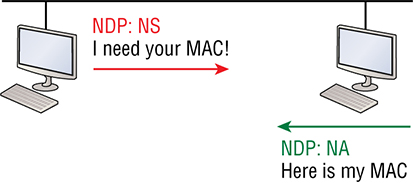
The part of the IPv6 address designated by the 24 bits farthest to the right is added to the end of the multicast address FF02:0:0:0:0:1:FF/104. When this address is queried, the corresponding host will send back its layer 2 address. Devices can find and keep track of other neighbor devices on the network in pretty much the same way. When I talked about RA and RS messages in Chapter 17 and told you that they use multicast traffic to request and send address information, that too is actually a function of ICMPv6—specifically, neighbor discovery. In IPv4, the protocol IGMP was used to allow a host device to tell its local router that it was joining a multicast group and would like to receive the traffic for that group. This IGMP function has been replaced by ICMPv6 and the process has been renamed multicast listener discovery. With IPv4, our hosts could have only one default gateway configured. If that router went down, we had to fix the router, change the default gateway, or run some type of virtual default gateway with other protocols created as a solution for this inadequacy in IPv4. Figure 18.20 shows how IPv6 devices find their default gateways using neighbor discovery. Figure 18.20 Router solicitation (RS) and router advertisement (RA) IPv6 hosts send a router solicitation (RS) onto their data link asking for all routers to respond, which they do using the multicast address FF02::2. Routers on the same link respond with a unicast to the requesting host or with a router advertisement (RA) using FF02::1. But that’s not all! Hosts can also send solicitations and advertisements between themselves using a neighbor solicitation (NS) and neighbor advertisement (NA), as shown in Figure 18.21. Figure 18.21 Neighbor solicitation (NS) and neighbor advertisement (NA) Remember that RA and RS gather or provide information about routers and NS and NA gather information about hosts. Also, remember that a “neighbor” is a host on the same data link or VLAN. With that foundational review in mind, here are the troubleshooting steps we’ll progress through during our investigation:
In order to troubleshoot this problem, we’ll use the same process of elimination, beginning with PC1. We’ve got to verify that it’s configured correctly and that IP is working properly. Let’s start by pinging the loopback address to verify the IPv6 stack: The IPv6 stack checks out, so let’s ping the Fa0/0 of R1, which PC1 is directly connected to on the same LAN, starting with the link-local address: Next, we’ll ping the global address on Fa0/0: Okay—looks like PC1 is configured and working on the local LAN to the R1 router. We’ve confirmed the Physical, Data Link, and Network layers between the PC1 and the
R1 router Fa0/0 interface. Our next move is to check the local connection on Server1 to the R2 router to verify that LAN. First we’ll ping the link-local address of the router from Server1: And next, we’ll ping the global address of Fa0/0 on R2: Let’s quickly summarize what we know at this point:
From here, we’ll go to PC1 and see if we can route to Server1: Wow—that’s not good. Looks like we might have a routing problem. And on this little network, we’re doing static IPv6 routing, so getting to the bottom of things will definitely take a little effort! But before we start looking into our potential routing issue, let’s check the link between R1 and R2. We’ll ping R2 from R1 to test the directly connected link. The first thing you need to do before attempting to ping between routers is verify your addresses—yes, verify them again! Let’s check out R1 and R2, then try pinging from R1 to R2: We can see that I now have the IPv6 addresses for both the R1’s and R2’s directly connected interfaces. The output also shows that I used the Ping program to verify layer 3 connectivity. Just as with IPv4, we need to resolve the logical (IPv6) address to a MAC address in order to communicate on the local LAN. But unlike IPv4, IPv6 doesn’t use ARP—it uses ICMPv6 neighbor solicitations instead. After the successful ping, we can now see the neighbor resolution table on R1: Let’s take a minute to talk about what each resolved address state indicates has happened: INCMP (incomplete) Address resolution is being performed on the entry. A neighbor solicitation message has been sent, but the neighbor message hasn’t yet been received. REACH (reachable) Positive confirmation has been received confirming that the path to the neighbor is functioning correctly. REACH is good! STALE The state is STALE when the interface hasn’t communicated within the neighbor reachable time frame. The next time the neighbor communicates, the state will change back to REACH. DELAY Occurs after the STALE state, when no reachability confirmation has been received within the DELAY_FIRST_PROBE_TIME. This means that the path was functioning but it hasn’t had communication within the neighbor reachable time frame. PROBE When in PROBE state, the configured interface is resending a neighbor solicitation and waiting for a reachability confirmation from a neighbor. We can verify our default gateway with IPv6 with the ipconfig command like this: Remember that the default gateway will be the link-local address of the router, and in this case, we can see that the address the host learned is truly the link-local address of the Fa0/0 interface of R1. The %11 is just used to identify an interface and isn’t used as part of the IPv6 address. The temporary IPv6 address, listed under the unicast IPv6 address as, “2001:db8:3c4d:3:2f33:44dd:211:1c3d,” was created by Windows to provide privacy from the EUI-64 format. This creates a global address from your host without using your MAC address by generating a random number for the interface and hashing it, which is then appended to the /64 prefix from the router. You can disable this feature with the following commands: In addition to the ipconfig command, we can use the command netsh interface ipv6 show neighbor to verify our default gateway address: Let’s establish the information we have right now:
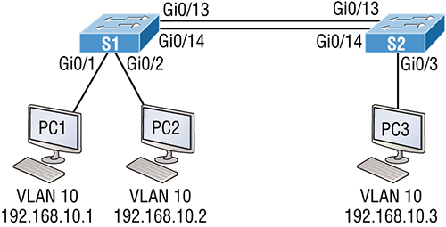
So all this tells us is that it’s now time to check our routing tables! We’ll start with the R1 router: All we can see in the output is the two directly connected interfaces configured on the router, and that won’t help us send IPv6 packets to the 2001:db8:3c4d:1::/64 subnet off of Fa0/0 on R2. So let’s find out what R2 can tell us: Now we’re talking—that tells us a lot more than R1’s table did! We have both of our directly connected configured LANs, Fa0/0 and Fa0/1, right there in the routing table, as well as a static route to 2001:DB8:3C4D:3::/64, which is the remote LAN Fa0/0 off of R1. This is good! Now let’s fix the route problem on R1 by adding a route that gives us access to the Server1 network and then move on to VLANs and trunking: I want to point out that I didn’t need to make the default route as difficult as I did. I entered both the exit interface and next-hop link-local address when just the exit interface or next-hop global addresses would be mandatory, but not the link-local. Next, we’ll verify that we can now ping from PC1 to Server1: Sweet—we’re golden with this particular scenario! But know it’s still possible to experience name resolution issues. If that were the case, you would just need to check your DNS server or local host table. We’ll move on in the same way we did in the IPv4 troubleshooting section by checking into our ACLs. This would be especially important if we were still plagued with a problem after troubleshooting all your local LANs and all other potential routing issues. To do that, just use the show ipv6 access-lists command to verify all configured ACLs on a router and use the show ipv6 interface command to verify if an ACL is attached to an interface. Once you’ve confirmed that your ACLs all make sense, you’re good to go! You know by now that VLANs are used to break up broadcast domains in a layer 2 switched network. You’ve also learned that we assign ports on a switch into a VLAN broadcast domain by using the switchport access vlan command. The access port carries traffic for a single VLAN that the port is a member of. If members of one VLAN want to communicate to members in the same VLAN that are located on a different switch, then a port between the two switches needs to either be configured as a member of this single VLAN or configured as a trunk link, which passes information on all VLANs by default. We’re going to use Figure 18.22 to reference as we go through the procedures for troubleshooting VLAN and trunking. Figure 18.22 VLAN connectivity I’m going to begin with VLAN troubleshooting and then we’ll get into trunk troubleshooting. A couple of key times to troubleshoot VLANs are when and if you lose connectivity between hosts and when you’re configuring new hosts into a VLAN but they’re not working. Here are the steps we’ll follow to troubleshoot VLANs:
And here’s a list of the commands we’ll be using in the section coming up: A manager calls and says they can’t communicate to the new sales team member that just connected to the network. How would you proceed to solve this issue? Well, because the sales hosts are in VLAN 10, we’ll begin with step 1 and verify that our databases on both switches are correct. First, I’ll use the show vlan or show vlan brief command to check if the expected VLAN is actually in the database. Here’s a look at the VLAN database on S1: This output shows that VLAN 10 is in the local database and that Gi0/1 and Gi0/2 are associated to VLAN 10. So next, we’ll go to step 2 and verify the CAM with the show mac address-table command: Okay—know that your switch will show quite a few MAC addresses assigned to the CPU at the top of the output. Those MAC addresses are used by the switch to manage the ports. The very first MAC address listed is the base MAC address of the switch and is used by STP in the bridge ID. In the preceding output, we can see that there are two MAC addresses associated with VLAN 10 and that they were dynamically learned. We can also establish that this MAC address is associated to Gi0/1. S1 looks really good! Let’s take a look at S2 now. First, let’s confirm that port PC3 is connected and check its configuration. I’ll use the command show interfaces
interface switchport command to do that: Here we can see that the port is enabled and that it’s set to dynamic desirable, meaning if it connects to another Cisco switch, it will desire to trunk on that link. The problem is, we’re using it as an access port, which is confirmed by the operational mode of static access. At the end of the output, the text shows Access Mode VLAN: 10 (Inactive). This isn’t good! Let’s examine S2’s CAM to see what we find out: Referring back to Figure 18.5, we can see that the host is connected to Gi0/3. The problem here is that we don’t see a MAC address dynamically associated to Gi0/3 in the MAC address table. So what do we know so far that can help us? Well first, we can see that Gi0/3 is configured into VLAN 10, but that VLAN is inactive. Second, the host off of Gi0/3 doesn’t appear in the CAM table. So now would be a good time to take a look at the VLAN database like this: Look at that—there’s no VLAN 10 in the database! Clearly this is our problem, but it’s also an easy one to fix by simply creating the VLAN in the database: That’s all there is to it. Now let’s check the CAM again: We’re good to go—the MAC address off of Gi0/3 shows in the MAC address table configured into VLAN 10. That was pretty straightforward, but if the port had been assigned to the wrong VLAN, I would have used the switch access vlan command to correct the VLAN membership. Here’s an example of how to do that: Nice—we can see that our port Gi0/3 is in the VLAN 10 membership. Now let’s try to ping from PC1 to PC3: No luck with that, so let’s see if PC1 can ping PC2: That worked! I can ping a host that’s a member of the same VLAN connected to the same switch, but I can’t ping to a host on another switch that’s a member of the same VLAN, which is VLAN 10. To get to the bottom of this, let’s quickly summarize what we’ve learned so far:
But since we still can’t ping to a host on another switch, we need to start checking out the connections between our switches. You’ll need to troubleshoot trunk links when you lose connectivity between hosts that are in the same VLAN but located on different switches. Cisco refers to this as “VLAN leaking.” Seems to me we are leaking VLAN 10 between switches somehow. These are the steps we’ll take to troubleshoot VLANs:
And here are the commands we’ll use to perform trunk troubleshooting: Okay, let’s get started by checking ports Gi0/13 and Gi0/14 on each switch because these are what the figure is showing as forming the connection between our switches. We’ll start with the show interfaces trunk command: Not a scrap of output—that’s definitely a bad sign! Let’s take another look at the show vlan output on S1 and see what we can find out: Nothing new from when we checked it a few minutes ago, but look there under VLAN 1—we can see interfaces Gi/013 and Gi0/14. This means that our ports between switches are members of VLAN 1 and will pass only VLAN 1 frames! Typically I’ll tell my students that if you type the show vlan command, you’re really typing the nonexistent “show access ports” command since this output shows interfaces in access mode but doesn’t show the trunk interfaces. This means that our ports between switches are access ports instead of trunk ports, so they’ll pass information about VLAN 1 only. Let’s go back over to the S2 switch to verify and see which port interfaces Gi0/13 and Gi0/14 are members of: Again, as with S1, the links between switches are showing in the output of the
show vlan command, which means that they are not trunk ports. We can use the
show interfaces
interface switchport command to verify this as well: This output tells us that interface Gi0/13 is in dynamic auto mode. But its operational mode is static access, meaning it’s not a trunk port. We can look closer at its trunking capabilities with the show interfaces
interface trunk command: Sure enough—the port is not trunking, but we already knew that. Now it’s confirmed. Notice that we can see that native VLAN is set to VLAN 1, which is the default native VLAN. This means that VLAN 1 is the default VLAN for untagged traffic. Now, before we check the native VLAN on S2 to verify that there isn’t a mismatch, I want to point out a key fact about trunking and how we would get these ports between switches to do that. Many Cisco switches support the Cisco proprietary Dynamic Trunking Protocol (DTP), which is used to manage automatic trunk negotiation between switches. Cisco recommends that you don’t go with this and to configure your switch ports manually instead. I agree with them! Okay, with that in mind, let’s check out our switch port Gi0/13 on S1 and view its DTP status. I’ll use the show dtp interface
interface command to view the DTP statistics: Did you notice that our port GI0/13 from S1 to S2 is an access port configured to autonegotiate using DTP? That’s interesting, and I want to dig a little deeper into the different port configurations and how they affect trunking capabilities to clarify why. Access Trunking is not allowed on a port set to access mode. Auto Will trunk to neighbor switch only if the remote port is set to on or to desirable mode. This creates the trunk based on the DTP request from the neighboring switch. Desirable This will trunk with all port modes except access. Ports set to dynamic desirable will communicate via DTP that the interface is attempting to become a trunk if the neighboring switch interface is able to become a trunk. Nonegotiate No DTP frames are generated from the interface. Can only be used if the neighbor interface is manually set as trunk or access. Trunk (on) Trunks with all switch port modes except access. Automatically enables trunking regardless of the state of the neighboring switch and regardless of any DTP requests. Let’s check out the different options available on the S1 switch with the switchport mode dynamic command: From interface mode, use the switch mode trunk command to turn trunking on. You can also use the switch mode dynamic command to set the port to auto or desirable trunking modes. To turn off DTP and any type of negotiation, use the switchport nonegotiate command. Let’s take a look at S2 and see if we can figure out why our two switches didn’t create a trunk: We can see that the port is in dynamic auto and that it’s operating as an access port. Let’s look into this further: Do you see the problem? Don’t be fooled—it’s not that they’re running in access mode; it’s because two ports in dynamic auto will not form a trunk! This is a really common problem to look for since most Cisco switches ship in dynamic auto. The other issue you need to be aware of, as well as check for, is the frame-tagging method. Some switches run 802.1q, some run both 802.1q and Inter-Switch Link (ISL) routing, so be sure the tagging method is compatible between all of your switches! It’s time to fix our problem on the trunk ports between S1 and S2. We only need to fix one side of each link since dynamic auto will trunk with a port set to desirable or on: Nice—it worked! With one side in Auto and the other now in Desirable, DTPs will be exchanged and they will trunk. Notice in the preceding output that the mode of S2’s Gi0/13 link is desirable and that the switches actually negotiated ISL as a trunk encapsulation—go figure! But don’t forget to notice the native VLAN. We’ll work on the frame-tagging method and native VLAN in a minute, but first, let’s configure our other link: Great, we now have two trunked links between switches. But I’ve got to say, I really don’t like the ISL method of frame tagging since it can’t send untagged frames across the link. So let’s change our native VLAN from the default of 1 to 392. The number 392 just randomly sounded good at the moment. Here’s what I entered on S1: See what I mean? I tried to change the native VLAN and ISL basically responded with, “What’s a native VLAN?” Very annoying, so I’m going to take care of that now! Now that’s more like it! As soon as I changed the encapsulation type on S1, DTP frames changed the frame-tagging method between S2 to 802.1q. Since I had already changed the native VLAN on port Gi0/13 on S1, the switch lets us know, via CDP, that we now have a native VLAN mismatch. Let’s proceed to deal with this by verifying our interfaces with the show interface trunk command: Notice that both links are running 802.1q, that S1 is in auto mode and S2 is in desirable mode. And we can see a native VLAN mismatch on port Gi0/13. We can also see the mismatched native VLAN with the show interfaces
interface switchport command by looking at both sides of the link like this: So this has got to be bad, right? I mean really—are we sending any frames down that link or not? Let’s see if we solved our little problem of not being able to ping to hosts from S1 to S2 and find out: Yes, it works! Not so bad after all. We’ve solved our problem, or at least most of it. Having a native VLAN mismatch only means you can’t send untagged frames down the link, which are essentially management frames like CDP, for example. So although it’s not the end of the world, it will prevent us from being able to remotely manage the switch. It will also prevent us from even sending any other types of traffic down just that one VLAN. So am I saying you can just leave this issue the way it is? Well, you could, but you won’t. No, you’ll fix it because if you don’t, CDP will send you a message every minute telling you that there’s a mismatch and drive you mad! This is how we’ll save our sanity: All better! Both sides of the same link between switches are now using native VLAN 392 on Gigabit Ethernet 0/13. I want you to know that you can have different native VLANs for each link and the link will still work, however, it is best to have them the same for management purposes. Each network is different and you have to make choices between options that will end up meeting your particular business requirements in the most optimal way. This chapter covered troubleshooting techniques from basic to advanced. Although most chapters in this book cover troubleshooting, this one focused purely on IPv4, IPv6 and VLAN/trunk troubleshooting. You learned how to troubleshoot step-by-step from a host to a remote device. Starting with IPv4, you learned the steps to test the host and the local connectivity and then how to troubleshoot remote connectivity. After that we moved on to IPv6 and proceeded to troubleshoot using the same techniques that you learned with IPv4. It’s important that you can use the verification commands that I used in each step of this chapter. Lastly, I covered VLAN and trunk troubleshooting and how to go step-by-step through a switched network using verification commands and narrowing down the problem. Understand how to Verify IP parameters for Client OS (Windows, Mac OS, Linux) To configure and verify the various OS’s, use tools such as ipconfig, ipconfig /all, and ifconfig Remember the Cisco steps in troubleshooting an IPv4 and IPv6 network.
Remember the commands to verify and troubleshoot IPv4 and IPv6. You need to remember and practice the commands used in this chapter, especially ping and traceroute (tracert on Windows). We also used the Windows commands ipconfig. route print and netsh, as well as Cisco’s commands show ip int brief, show interface, and show route. Remember how to verify an ARP cache with IPv6. The command show ipv6 neighbors shows the IP-to-MAC-address resolution table on a Cisco router. Remember to look at the statistics on a router and switch interface to determine problems.
You’ve got to be able to analyze interface statistics to spot problems if they exist, including speed and duplex settings, input queue drops, output queue drops, and input and output errors. Understand what a native VLAN is and how to change it. A native VLAN works with only 802.1q trunks and allows untagged traffic to traverse the trunk link. This is VLAN 1 by default on all Cisco switches, but it can be changed for security reasons with the switchport native vlan
vlan command. The answers to these questions are found in the Appendix. You need to verify the IPv6 ARP cache on a router and see that the state of an entry is REACH. What does REACH mean?
What’s the most common cause of interface errors?
Which command will verify the DTP status on a switch interface?
What mode will not allow DTP frames generated from a switch port?
The following output was generated by which command?
Which of the following states tells you that an interface has not communicated within the neighbor-reachable time frame?
You receive a call from a user who says that they can’t log in to a remote server, which only runs IPv6. Based on the output, what could the problem be?
Your host cannot reach remote networks. Based on the output, what’s the problem?
Which two commands will show you if you have a native VLAN mismatch?
You connect two new Cisco 3560 switches together and expect them to use DTP and create a trunk. But, when you check statistics, you find that they are access ports and didn’t negotiate. Why didn’t DTP work on these Cisco switches?
What command can used to verify the IP address on a Mac?
![]() 1.4 Identify interface and cable issues (collisions, errors, mismatch duplex, and/or speed)
1.4 Identify interface and cable issues (collisions, errors, mismatch duplex, and/or speed)![]() 1.6 Configure and verify IPv4 addressing and subnetting
1.6 Configure and verify IPv4 addressing and subnetting![]() 1.8 Configure and verify IPv6 addressing and prefix
1.8 Configure and verify IPv6 addressing and prefix![]() 1.10 Verify IP parameters for Client OS (Windows,
Mac OS, Linux)
1.10 Verify IP parameters for Client OS (Windows,
Mac OS, Linux)
![]() 2.2 Configure and verify interswitch connectivity
2.2 Configure and verify interswitch connectivity
 Especially at first, it’s going to seem like we’re covering the same ground already covered in other chapters. It’s just that troubleshooting is such a major focus of the Cisco CCNA objectives I’d be letting you down if I didn’t make sure you’ve seriously got it down. So to make sure your skills are solid, we’re going start with a deep dive into troubleshooting with IP, IPv6, and virtual LANs (VLANs). Having the fundamentals of IP and IPv6 routing, plus a working knowledge of VLANs and trunking nailed down tight is also key if you’re going to win at this!
![]() To find your included bonus material, as well as Todd Lammle videos, practice questions & hands-on labs, please see www.lammle.com/ccna
To find your included bonus material, as well as Todd Lammle videos, practice questions & hands-on labs, please see www.lammle.com/ccnaEndpoints
Desktops/Laptops
Mobile Phones/Tablets
Access Points
IP Phones
Internet of Things
Servers
Server Roles
IP Config
Windows 10

![]() If you want to change the IPv6 address you’d go into the Version 6 properties instead.
If you want to change the IPv6 address you’d go into the Version 6 properties instead.
macOS


Ubuntu/Red Hat


Troubleshooting IP Network Connectivity
C:UsersTodd Lammle>
ipconfig

Windows IP Configuration

Ethernet adapter Local Area Connection:

   Connection-specific DNS Suffix  . : localdomain
   Link-local IPv6 Address . . . . . : fe80::64e3:76a2:541f:ebcb%11
   IPv4 Address. . . . . . . . . . . : 10.1.1.10
   Subnet Mask . . . . . . . . . . . : 255.255.255.0
   Default Gateway . . . . . . . . . : 10.1.1.1
C:UsersTodd Lammle>
route print
[output cut]
IPv4 Route Table
=======================================================================
Active Routes:
Network Destination      Netmask        Gateway       Interface  Metric
          0.0.0.0        0.0.0.0        10.1.1.10     10.1.1.1   10
[output cut]
![]() To meet Cisco’s objectives, it’s extremely important to be able to check and verify the default gateway on a host and that this address also matches the router’s interface!
To meet Cisco’s objectives, it’s extremely important to be able to check and verify the default gateway on a host and that this address also matches the router’s interface!C:UsersTodd Lammle>ping 127.0.0.1
Pinging 127.0.0.1 with 32 bytes of data:
Reply from 127.0.0.1: bytes=32 time<1ms TTL=128
Reply from 127.0.0.1: bytes=32 time<1ms TTL=128
Reply from 127.0.0.1: bytes=32 time<1ms TTL=128
Reply from 127.0.0.1: bytes=32 time<1ms TTL=128
Ping statistics for 127.0.0.1:
Packets: Sent = 4, Received = 4, Lost = 0 (0% loss),
Approximate round trip times in milli-seconds:
Minimum = 0ms, Maximum = 0ms, Average = 0ms
C:UsersTodd Lammle>ping 10.1.1.10

Pinging 10.1.1.10 with 32 bytes of data:
Reply from 10.1.1.10: bytes=32 time<1ms TTL=128
Reply from 10.1.1.10: bytes=32 time<1ms TTL=128
Reply from 10.1.1.10: bytes=32 time<1ms TTL=128
Reply from 10.1.1.10: bytes=32 time<1ms TTL=128

Ping statistics for 10.1.1.10:
    Packets: Sent = 4, Received = 4, Lost = 0 (0% loss),
Approximate round trip times in milli-seconds:
    Minimum = 0ms, Maximum = 0ms, Average = 0ms
C:UsersTodd Lammle>ping 10.1.1.1

Pinging 10.1.1.1 with 32 bytes of data:
Reply from 10.1.1.1: bytes=32 time<1ms TTL=128
Reply from 10.1.1.1: bytes=32 time<1ms TTL=128
Reply from 10.1.1.1: bytes=32 time<1ms TTL=128
Reply from 10.1.1.1: bytes=32 time<1ms TTL=128

Ping statistics for 10.1.1.1:
    Packets: Sent = 4, Received = 4, Lost = 0 (0% loss),
Approximate round trip times in milli-seconds:
    Minimum = 0ms, Maximum = 0ms, Average = 0ms
C:UsersTodd Lammle>ping 172.16.20.254

Pinging 172.16.20.254 with 32 bytes of data:
Request timed out.
Request timed out.
Request timed out.
Request timed out.

Ping statistics for 172.16.20.254:
    Packets: Sent = 4, Received = 0, Lost = 4 (100% loss),
C:UsersTodd Lammle>
tracert 172.16.20.254

Tracing route to 172.16.20.254 over a maximum of 30 hops

  1     1 ms     1 ms    <1 ms  10.1.1.1
  2     *        *        *     Request timed out.
  3     *        *        *     Request timed out.
R2#ping 172.16.20.254

Pinging 172.16.20.254 with 32 bytes of data:
Reply from 172.16.20.254: bytes=32 time<1ms TTL=128
Reply from 172.16.20.254: bytes=32 time<1ms TTL=128
Reply from 172.16.20.254: bytes=32 time<1ms TTL=128
Reply from 172.16.20.254: bytes=32 time<1ms TTL=128

Ping statistics for 172.16.20.254:
    Packets: Sent = 4, Received = 0, Lost = 4 (100% loss),
C:UsersServer1>
ipconfig

Windows IP Configuration

Ethernet adapter Local Area Connection:

   Connection-specific DNS Suffix  . : localdomain
   Link-local IPv6 Address . . . . . : fe80::7723:76a2:e73c:2acb%11
   IPv4 Address. . . . . . . . . . . : 172.16.20.254
   Subnet Mask . . . . . . . . . . . : 255.255.255.0
   Default Gateway . . . . . . . . . : 172.16.20.1
R2#sh int fa0/0
FastEthernet0/0 is up, line protocol is up
[output cut]
Full-duplex, 100Mb/s, 100BaseTX/FX
  ARP type: ARPA, ARP Timeout 04:00:00
  Last input 00:00:05, output 00:00:01, output hang never
  Last clearing of "show interface" counters never
Input queue: 0/75/0/0 (size/max/drops/flushes); Total output drops: 0
  Queueing strategy: fifo
  Output queue: 0/40 (size/max)
  5 minute input rate 0 bits/sec, 0 packets/sec
  5 minute output rate 0 bits/sec, 0 packets/sec
     1325 packets input, 157823 bytes
     Received 1157 broadcasts (0 IP multicasts)
     0 runts, 0 giants, 0 throttles
     0 input errors, 0 CRC, 0 frame, 0 overrun, 0 ignored
     0 watchdog
     0 input packets with dribble condition detected
     2294 packets output, 244630 bytes, 0 underruns
     0 output errors, 0 collisions, 3 interface resets
     347 unknown protocol drops
     0 babbles, 0 late collision, 0 deferred
     4 lost carrier, 0 no carrier
     0 output buffer failures, 0 output buffers swapped out
Switch(config)#int gi0/1
Switch(config-if)#speed ?
  10    Force 10 Mbps operation
  100   Force 100 Mbps operation
  1000  Force 1000 Mbps operation
  auto  Enable AUTO speed configuration
Switch(config-if)#speed 1000
Switch(config-if)#duplex  ?
  auto  Enable AUTO duplex configuration
  full  Force full duplex operation
  half  Force half-duplex operation
Switch(config-if)#duplex  full
R1>
sh ip route
[output cut]
Gateway of last resort is 192.168.10.254 to network 0.0.0.0

S*    0.0.0.0/0 [1/0] via 192.168.10.254
      10.0.0.0/8 is variably subnetted, 2 subnets, 2 masks
C        10.1.1.0/24 is directly connected, FastEthernet0/0
L        10.1.1.1/32 is directly connected, FastEthernet0/0
      192.168.10.0/24 is variably subnetted, 2 subnets, 2 masks
C        192.168.10.0/24 is directly connected, FastEthernet0/1
L        192.168.10.1/32 is directly connected, FastEthernet0/1
R1>sh ip int brief
Interface               IP-Address    OK? Method Status              Protocol
FastEthernet0/0         10.1.1.1      YES manual up                    up
FastEthernet0/1         192.168.10.1  YES manual up                    up
Serial0/0/0             unassigned    YES unset  administratively down down
Serial0/1/0             unassigned    YES unset  administratively down down
R1>ping 192.168.10.254
Type escape sequence to abort.
Sending 5, 100-byte ICMP Echos to 192.168.10.254, timeout is 2 seconds:
!!!!!
Success rate is 100 percent (5/5), round-trip min/avg/max = 1/2/4 ms
R2>sh ip int brief
Interface               IP-Address      OK? Method Status              Protocol
FastEthernet0/0         172.16.20.1     YES manual up                    up
FastEthernet0/1         192.168.10.254  YES manual up                    up
R2>ping 192.168.10.1
Type escape sequence to abort.
Sending 5, 100-byte ICMP Echos to 192.168.10.1, timeout is 2 seconds:
!!!!!
Success rate is 100 percent (5/5), round-trip min/avg/max = 1/2/4 ms
R2>sh ip route
[output cut]
Gateway of last resort is not set

      10.0.0.0/24 is subnetted, 1 subnets
S        10.1.1.0 is directly connected, FastEthernet0/0
      172.16.0.0/16 is variably subnetted, 2 subnets, 2 masks
C        172.16.20.0/24 is directly connected, FastEthernet0/0
L        172.16.20.1/32 is directly connected, FastEthernet0/0
      192.168.10.0/24 is variably subnetted, 2 subnets, 2 masks
C        192.168.10.0/24 is directly connected, FastEthernet0/1
L        192.168.10.254/32 is directly connected, FastEthernet0/1
R2#config t
R2(config)#no ip route 10.1.1.0 255.255.255.0 fa0/0
R2(config)#ip route 10.1.1.0 255.255.255.0 192.168.10.1
C:UsersTodd Lammle>ping 172.16.20.254

Pinging 172.16.20.254 with 32 bytes of data:
Reply from 172.16.20.254: bytes=32 time<1ms TTL=128
Reply from 172.16.20.254: bytes=32 time<1ms TTL=128
Reply from 172.16.20.254: bytes=32 time<1ms TTL=128
Reply from 172.16.20.254: bytes=32 time<1ms TTL=128

Ping statistics for 172.16.20.254
    Packets: Sent = 4, Received = 4, Lost = 0 (0% loss),
Approximate round trip times in milli-seconds:
    Minimum = 0ms, Maximum = 0ms, Average = 0ms
C:UsersTodd Lammle>telnet 172.16.20.254
Connecting To 172.16.20.254...Could not open connection to the host, on
port 23: Connect failed
R1>ping 172.16.20.254
Type escape sequence to abort.
Sending 5, 100-byte ICMP Echos to 172.16.20.254, timeout is 2 seconds:
!!!!!
Success rate is 100 percent (5/5), round-trip min/avg/max = 1/1/4 ms
R1>telnet 172.16.20.254
Trying 172.16.20.254 ...
% Destination unreachable; gateway or host down
R2#telnet 172.16.20.254
Trying 172.16.20.254 ... Open

User Access Verification

Password:
R2>sh access-lists
Extended IP access list 110
    10 permit icmp any any (25 matches)
R2>sh ip int fa0/0
FastEthernet0/0 is up, line protocol is up
  Internet address is 172.16.20.1/24
  Broadcast address is 255.255.255.255
  Address determined by setup command
  MTU is 1500 bytes
  Helper address is not set
  Directed broadcast forwarding is disabled
  Outgoing access list is 110
  Inbound  access list is not set
R2#config t
R2(config)#no access-list 110
R1#telnet 172.16.20.254
Trying 172.16.20.254 ... Open

User Access Verification

Password:
R1#telnet Server1
Translating "Server1"...domain server (255.255.255.255)

% Bad IP address or host name
R1(config)#ip host Server1 172.16.20.254
R1(config)#^Z
R1#telnet Server1
Trying Server1 (172.16.20.254)... Open

User Access Verification

Password:
R1#telnet 172.16.20.254 80
Trying 172.16.20.254, 80 ... Open
Using SPAN for Troubleshooting
S1(config)#monitor session 1 source interface f0/1
S1(config)#monitor session 1 dest interface f0/2
S1(config)#do sh monitor
Session 1
---------
Type                   : Local Session
Source Ports           :
    Both               : Fa0/1
Destination Ports      : Fa0/2
    Encapsulation      : Native
          Ingress      : Disabled
Configuring and Verifying Extended Access Lists
R1#telnet 172.16.20.254
Trying 172.16.20.254 ... Open
Server1>
R1(config)#ip access-list extended Block_Telnet
R1(config-ext-nacl)#
R1(config-ext-nacl)#deny tcp host 10.1.1.1 host 172.16.20.254 eq 23
R1(config-ext-nacl)#permit ip any any
R1(config-ext-nacl)#do sh access-list
Extended IP access list Block_Telnet
    10 deny tcp host 10.1.1.1 host 172.16.20.254 eq telnet
    20 permit ip any any
R1(config)#int fa0/0
R1(config-if)#ip access-group Block_Telnet in
R1#telnet 172.16.20.254
Trying 172.16.20.254 ... Open
Server1>
R1#sh access-list
Extended IP access list Block_Telnet
    10 deny tcp host 10.1.1.1 host 172.16.20.254 eq telnet
    20 permit ip any any
R1(config)#ip access-list extended Block_Telnet
R1(config-ext-nacl)#no 10
R1(config-ext-nacl)#10 deny tcp host 10.1.1.10 host 172.16.20.254 eq 23
R1#telnet 172.16.20.254
Trying 172.16.20.254 ...
% Destination unreachable; gateway or host down
R1#sh access-list
Extended IP access list Block_Telnet
    10 deny tcp host 10.1.1.10 host 172.16.20.254 eq telnet (58 matches)
    20 permit ip any any (86 matches)
R1#sh ip int f0/0
FastEthernet0/0 is up, line protocol is up
  Internet address is 10.10.10.1/24
  Broadcast address is 255.255.255.255
  Address determined by non-volatile memory
  MTU is 1500 bytes
  Helper address is not set
  Directed broadcast forwarding is disabled
  Multicast reserved groups joined: 224.0.0.10
  Outgoing access list is not set

Inbound  access list is Block_Telnet
  Proxy ARP is enabled
[output cut]
Troubleshooting IPv6 Network Connectivity
ICMPv6
Neighbor Discovery (NDP)

C:UsersTodd Lammle>ping ::1

Pinging ::1 with 32 bytes of data:
Reply from ::1: time<1ms
Reply from ::1: time<1ms
Reply from ::1: time<1ms
Reply from ::1: time<1ms
C:UsersTodd Lammle>ping fe80::21a:6dff:fe37:a44e

Pinging fe80:21a:6dff:fe37:a44e with 32 bytes of data:
Reply from fe80::21a:6dff:fe37:a44e: time<1ms
Reply from fe80::21a:6dff:fe37:a44e: time<1ms
Reply from fe80::21a:6dff:fe37:a44e: time<1ms
Reply from fe80::21a:6dff:fe37:a44e: time<1ms
C:UsersTodd Lammle>ping 2001:db8:3c4d:3:21a:6dff:fe37:a44e

Pinging 2001:db8:3c4d:3:21a:6dff:fe37:a44e with 32 bytes of data:
Reply from 2001:db8:3c4d:3:21a:6dff:fe37:a44e: time<1ms
Reply from 2001:db8:3c4d:3:21a:6dff:fe37:a44e: time<1ms
Reply from 2001:db8:3c4d:3:21a:6dff:fe37:a44e: time<1ms
Reply from 2001:db8:3c4d:3:21a:6dff:fe37:a44e: time<1ms
C:UsersServer1>ping fe80::21a:6dff:fe64:9b2

Pinging fe80::21a:6dff:fe64:9b2  with 32 bytes of data:
Reply from fe80::21a:6dff:fe64:9b2: time<1ms
Reply from fe80::21a:6dff:fe64:9b2: time<1ms
Reply from fe80::21a:6dff:fe64:9b2: time<1ms
Reply from fe80::21a:6dff:fe64:9b2: time<1ms
C:UsersServer1>ping 2001:db8:3c4d:1:21a:6dff:fe37:a443

Pinging 2001:db8:3c4d:1:21a:6dff:fe37:a443 with 32 bytes of data:
Reply from 2001:db8:3c4d:1:21a:6dff:fe37:a443: time<1ms
Reply from 2001:db8:3c4d:1:21a:6dff:fe37:a443: time<1ms
Reply from 2001:db8:3c4d:1:21a:6dff:fe37:a443: time<1ms
Reply from 2001:db8:3c4d:1:21a:6dff:fe37:a443: time<1ms
C:UsersTodd Lammle>tracert 2001:db8:3c4d:1:a14c:8c33:2d1:be3d

Tracing route to 2001:db8:3c4d:1:a14c:8c33:2d1:be3d over a maximum of 30 hops

  1     Destination host unreachable.
R1#sh ipv6 int brief
FastEthernet0/0            [up/up]
    FE80::21A:6DFF:FE37:A44E
    2001:DB8:3C4D:3:21A:6DFF:FE37:A44E
FastEthernet0/1            [up/up]
    FE80::21A:6DFF:FE37:A44F
    2001:DB8:3C4D:2:21A:6DFF:FE37:A44F

R2#sh ipv6 int brief
FastEthernet0/0            [up/up]
    FE80::21A:6DFF:FE64:9B2
    2001:DB8:3C4D:1:21A:6DFF:FE37:A443
FastEthernet0/1            [up/up]
    FE80::21A:6DFF:FE64:9B3
    2001:DB8:3C4D:2:21A:6DFF:FE64:9B3

R1#ping 2001:DB8:3C4D:2:21A:6DFF:FE64:9B3
Type escape sequence to abort.
Sending 5, 100-byte ICMP Echos to ping 2001:DB8:3C4D:2:21A:6DFF:FE64:9B3, timeout
is 2 seconds:
!!!!!
Success rate is 100 percent (5/5), round-trip min/avg/max = 0/2/8 ms
R1#sh ipv6 neighbors
IPv6 Address                          Age Link-layer Addr
State Interface
FE80::21A:6DFF:FE64:9B3                 0 001a.6c46.9b09  DELAY Fa0/1
2001:DB8:3C4D:2:21A:6DFF:FE64:9B3       0 001a.6c46.9b09  REACH Fa0/1
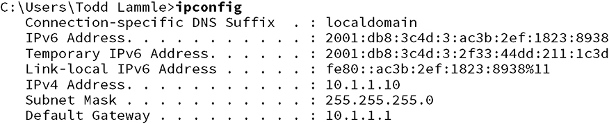
C:UsersTodd Lammle>ipconfig
   Connection-specific DNS Suffix  . : localdomain
   IPv6 Address. . . . . . . . . . . : 2001:db8:3c4d:3:ac3b:2ef:1823:8938
   Temporary IPv6 Address. . . . . . : 2001:db8:3c4d:3:2f33:44dd:211:1c3d
   Link-local IPv6 Address . . . . . : fe80::ac3b:2ef:1823:8938%11
   IPv4 Address. . . . . . . . . . . : 10.1.1.10
   Subnet Mask . . . . . . . . . . . : 255.255.255.0
   Default Gateway . . . . . . . . . : Fe80::21a:6dff:fe37:a44e%11
      10.1.1.1
![]()
Temporary IPv6 Addressesnetsh interface ipv6 set global randomizeidentifiers=disabled
netsh interface ipv6 set privacy state-disabled
C:UsersTodd Lammle>
netsh interface ipv6 show neighbor
[output cut]

Interface 11: Local Area Connection

Internet Address                              Physical Address   Type
--------------------------------------------  -----------------  -----------
2001:db8:3c4d:3:21a:6dff:fe37:a44e            00-1a-6d-37-a4-4e  (Router)

Fe80::21a:6dff:fe37:a44e                      00-1a-6d-37-a4-4e  (Router)
ff02::1                                       33-33-00-00-00-01  Permanent
ff02::2                                       33-33-00-00-00-02  Permanent
ff02::c                                       33-33-00-00-00-0c  Permanent
ff02::16                                      33-33-00-00-00-16  Permanent
ff02::fb                                      33-33-00-00-00-fb  Permanent
ff02::1:2                                     33-33-00-01-00-02  Permanent
ff02::1:3                                     33-33-00-01-00-03  Permanent
ff02::1:ff1f:ebcb                             33-33-ff-1f-eb-cb  Permanent
![]() I’ve checked the default gateway addresses on Server1 and they are correct. They should be, because this is provided directly from the router with an ICMPv6 RA (router advertisement) message. The output for that verification is not displayed.
I’ve checked the default gateway addresses on Server1 and they are correct. They should be, because this is provided directly from the router with an ICMPv6 RA (router advertisement) message. The output for that verification is not displayed.
R1#sh ipv6 route
C   2001:DB8:3C4D:2::/64 [0/0]
     via FastEthernet0/1, directly connected
L   2001:DB8:3C4D:2:21A:6DFF:FE37:A44F/128 [0/0]
     via FastEthernet0/1, receive
C   2001:DB8:3C4D:3::/64 [0/0]
     via FastEthernet0/0, directly connected
L   2001:DB8:3C4D:3:21A:6DFF:FE37:A44E/128 [0/0]
     via FastEthernet0/0, receive
L   FF00::/8 [0/0]
     via Null0, receive
R2#sh ipv6 route
C   2001:DB8:3C4D:1::/64 [0/0]
     via FastEthernet0/0, directly connected
L   2001:DB8:3C4D:1:21A:6DFF:FE37:A443/128 [0/0]
     via FastEthernet0/0, receive
C   2001:DB8:3C4D:2::/64 [0/0]
     via FastEthernet0/1, directly connected
L   2001:DB8:3C4D:2:21A:6DFF:FE64:9B3/128 [0/0]
     via FastEthernet0/1, receive
S   2001:DB8:3C4D:3::/64 [1/0]

   via 2001:DB8:3C4D:2:21B:D4FF:FE0A:539
L   FF00::/8 [0/0]
     via Null0, receive
R1(config)#ipv6 route ::/0 fastethernet 0/1 FE80::21A:6DFF:FE64:9B3
C:UsersTodd Lammle>
ping 2001:db8:3c4d:1:a14c:8c33:2d1:be3d

Pinging 2001:db8:3c4d:1:a14c:8c33:2d1:be3d with 32 bytes of data:
Reply from 2001:db8:3c4d:1:a14c:8c33:2d1:be3d: time<1ms
Reply from 2001:db8:3c4d:1:a14c:8c33:2d1:be3d: time<1ms
Reply from 2001:db8:3c4d:1:a14c:8c33:2d1:be3d: time<1ms
Reply from 2001:db8:3c4d:1:a14c:8c33:2d1:be3d: time<1ms
Troubleshooting VLAN Connectivity
VLAN Troubleshooting
Show vlan
Show mac address-table
Show interfaces
interface switchport
switchport access vlan
vlan
VLAN Troubleshooting Scenario
S1#sh vlan

VLAN Name                             Status    Ports
---- -------------------------------- --------- -------------------------------
1    default                          active    Gi0/3, Gi0/4, Gi0/5, Gi0/6
                                                Gi0/7, Gi0/8, Gi0/9, Gi0/10
                                                Gi0/11, Gi0/12, Gi0/13, Gi0/14
                                                Gi0/15, Gi0/16, Gi0/17, Gi0/18
                                                Gi0/19, Gi0/20, Gi0/21, Gi0/22
                                                Gi0/23, Gi0/24, Gi0/25, Gi0/26
                                                Gi0/27, Gi0/28
10   Sales                            active    Gi0/1, Gi0/2
20   Accounting                       active
26   Automation10                     active
27   VLAN0027                         active
30   Engineering                      active
170  VLAN0170                         active
501  Private501                       active
502  Private500                       active
[output cut]
S1#sh mac address-table
          Mac Address Table
-------------------------------------------

Vlan    Mac Address       Type        Ports
----    -----------       --------    -----
 All    0100.0ccc.cccc    STATIC      CPU
[output cut]
   1    000d.2830.2f00    DYNAMIC     Gi0/24
   1    0021.1c91.0d8d    DYNAMIC     Gi0/13
   1    0021.1c91.0d8e    DYNAMIC     Gi0/14
   1    b414.89d9.1882    DYNAMIC     Gi0/17
   1    b414.89d9.1883    DYNAMIC     Gi0/18
   1    ecc8.8202.8282    DYNAMIC     Gi0/15
   1    ecc8.8202.8283    DYNAMIC     Gi0/16
  10    001a.2f55.c9e8    DYNAMIC     Gi0/1

  10    001b.d40a.0538    DYNAMIC     Gi0/2
Total Mac Addresses for this criterion: 29
S2#sh interfaces gi0/3 switchport
Name: Gi0/3
Switchport: Enabled

Administrative Mode: dynamic desirable

Operational Mode: static access
Administrative Trunking Encapsulation: negotiate
Operational Trunking Encapsulation: native
Negotiation of Trunking: On
Access Mode VLAN: 10 (Inactive)
Trunking Native Mode VLAN: 1 (default)
[output cut]
S2#sh mac address-table
          Mac Address Table
-------------------------------------------

Vlan    Mac Address       Type        Ports
----    -----------       --------    -----
 All    0100.0ccc.cccc    STATIC      CPU
 [output cut]
   1    001b.d40a.0538    DYNAMIC     Gi0/13
   1    0021.1bee.a70d    DYNAMIC     Gi0/13
   1    b414.89d9.1884    DYNAMIC     Gi0/17
   1    b414.89d9.1885    DYNAMIC     Gi0/18
   1    ecc8.8202.8285    DYNAMIC     Gi0/16
Total Mac Addresses for this criterion: 26
S2#sh vlan brief

VLAN Name                             Status    Ports
---- -------------------------------- --------- -------------------------------
1    default                          active    Gi0/1, Gi0/2, Gi0/4, Gi0/5
                                                Gi0/6, Gi0/7, Gi0/8, Gi0/9
                                                Gi0/10, Gi0/11, Gi0/12, Gi0/13
                                                Gi0/14, Gi0/15, Gi0/16, Gi0/17
                                                Gi0/18, Gi0/19, Gi0/20, Gi0/21
                                                Gi0/22, Gi0/23, Gi0/24, Gi0/25
                                                Gi0/26, Gi0/27, Gi0/28
26   Automation10                     active
27   VLAN0027                         active
30   Engineering                      active
170  VLAN0170                         active
[output cut]
S2#config t
S2(config)#vlan 10
S2(config-vlan)#name Sales
S2#sh mac address-table
          Mac Address Table
-------------------------------------------

Vlan    Mac Address       Type        Ports
----    -----------       --------    -----
 All    0100.0ccc.cccc    STATIC      CPU
[output cut]
   1    0021.1bee.a70d    DYNAMIC     Gi0/13
  10    001a.6c46.9b09    DYNAMIC     Gi0/3
Total Mac Addresses for this criterion: 22
S2#config t
S2(config)#int gi0/3
S2(config-if)#switchport access vlan 10
S2(config-if)#do sh vlan

VLAN Name                             Status    Ports
---- -------------------------------- --------- -------------------------------
1    default                          active    Gi0/1, Gi0/2, Gi0/4, Gi0/5
                                                Gi0/6, Gi0/7, Gi0/8, Gi0/9
                                                Gi0/10, Gi0/11, Gi0/12, Gi0/13
                                                Gi0/14, Gi0/15, Gi0/16, Gi0/17
                                                Gi0/18, Gi0/19, Gi0/20, Gi0/21
                                                Gi0/22, Gi0/23, Gi0/24, Gi0/25
                                                Gi0/26, Gi0/27, Gi0/28
10   Sales                            active    Gi0/3
PC1#ping 192.168.10.3
Type escape sequence to abort.
Sending 5, 100-byte ICMP Echos to 192.168.10.3, timeout is 2 seconds:
.....
Success rate is 0 percent (0/5)
PC1#ping 192.168.10.2
Type escape sequence to abort.
Sending 5, 100-byte ICMP Echos to 192.168.10.2, timeout is 2 seconds:
!!!!!
Success rate is 100 percent (5/5), round-trip min/avg/max = 1/2/4 ms
PC1#
Trunk Troubleshooting
Show interfaces trunk
Show vlan
Show interfaces
interface trunk
Show interfaces
interface switchport
Show dtp interface
interface
switchport mode
switchport mode dynamic
switchport trunk native vlan
vlan
S1>sh interfaces trunk

S2>sh interfaces trunk
S1>sh vlan brief

VLAN Name                             Status    Ports
---- -------------------------------- --------- -------------------------------
1    default                          active    Gi0/3, Gi0/4, Gi0/5, Gi0/6
                                                Gi0/7, Gi0/8, Gi0/9, Gi0/10
                                                Gi0/11, Gi0/12, Gi0/13, Gi0/14
                                                Gi0/15, Gi0/16, Gi0/17, Gi0/18
                                                Gi0/19, Gi0/20, Gi0/21, Gi0/22
                                                Gi0/23, Gi0/24, Gi0/25, Gi0/26
                                                Gi0/27, Gi0/28
10   Sales                            active    Gi0/1, Gi0/2
20   Accounting                       active
[output cut]
S2>sh vlan brief

VLAN Name                             Status    Ports
---- -------------------------------- --------- -------------------------------
1    default                          active    Gi0/1, Gi0/2, Gi0/4, Gi0/5
                                                Gi0/6, Gi0/7, Gi0/8, Gi0/9
                                                Gi0/10, Gi0/11, Gi0/12, Gi0/13
                                                Gi0/14, Gi0/15, Gi0/16, Gi0/17
                                                Gi0/18, Gi0/19, Gi0/20, Gi0/21
                                                Gi0/22, Gi0/23, Gi0/24, Gi0/25
                                                Gi0/26, Gi0/27, Gi0/28
10   Sales                            active    Gi0/3
S1#sho interfaces gi0/13 switchport
Name: Gi0/13
Switchport: Enabled
Administrative Mode: dynamic auto
Operational Mode: static access
Administrative Trunking Encapsulation: negotiate
Operational Trunking Encapsulation: native
Negotiation of Trunking: On
Access Mode VLAN: 1 (default)
Trunking Native Mode VLAN: 1 (default)
S1#sh interfaces gi0/1 trunk

Port        Mode         Encapsulation  Status        Native vlan
Gi0/1       auto         negotiate      not-trunking  1
[output cut]
S1#sh dtp interface gi0/13
DTP information for GigabitEthernet0/13:
  TOS/TAS/TNS:                              ACCESS/AUTO/ACCESS
  TOT/TAT/TNT:                              NATIVE/NEGOTIATE/NATIVE
  Neighbor address 1:                       00211C910D8D
  Neighbor address 2:                       000000000000
  Hello timer expiration (sec/state):       12/RUNNING
  Access timer expiration (sec/state):      never/STOPPED
S1(config-if)#switchport mode ?
  access        Set trunking mode to ACCESS unconditionally
  dot1q-tunnel  set trunking mode to TUNNEL unconditionally
  dynamic       Set trunking mode to dynamically negotiate access or trunk mode
  private-vlan  Set private-vlan mode
  trunk         Set trunking mode to TRUNK unconditionally

S1(config-if)#switchport mode dynamic ?
  auto       Set trunking mode dynamic negotiation parameter to AUTO
  desirable  Set trunking mode dynamic negotiation parameter to DESIRABLE
S2#sh int gi0/13 switchport
Name: Gi0/13
Switchport: Enabled
Administrative Mode: dynamic auto
Operational Mode: static access
Administrative Trunking Encapsulation: negotiate
Operational Trunking Encapsulation: native
Negotiation of Trunking: On
S2#sh dtp interface gi0/13
DTP information for GigabitEthernet0/3:
  DTP information for GigabitEthernet0/13:
  TOS/TAS/TNS:                              ACCESS/AUTO/ACCESS
  TOT/TAT/TNT:                              NATIVE/NEGOTIATE/NATIVE
  Neighbor address 1:                       000000000000
  Neighbor address 2:                       000000000000
  Hello timer expiration (sec/state):       17/RUNNING
  Access timer expiration (sec/state):      never/STOPPED
S2(config)#int gi0/13
S2(config-if)#switchport mode dynamic desirable
23:11:37:%LINEPROTO-5-UPDOWN:Line protocol on Interface GigabitEthernet0/13, changed state to down
23:11:37:%LINEPROTO-5-UPDOWN:Line protocol on Interface Vlan1, changed state to down
23:11:40:%LINEPROTO-5-UPDOWN:Line protocol on Interface GigabitEthernet0/13, changed state to up
23:12:10:%LINEPROTO-5-UPDOWN:Line protocol on Interface Vlan1, changed state to up
S2(config-if)#do show int trunk

Port        Mode         Encapsulation  Status        Native vlan
Gi0/13      desirable    n-isl          trunking      1
[output cut]
S2(config-if)#int gi0/14
S2(config-if)#switchport mode dynamic desirable
23:12:%LINEPROTO-5-UPDOWN:Line protocol on Interface GigabitEthernet0/14, changed state to down
23:12:%LINEPROTO-5-UPDOWN:Line protocol on Interface GigabitEthernet0/14, changed state to up
S2(config-if)#do show int trunk

Port        Mode         Encapsulation  Status        Native vlan
Gi0/13      desirable    n-isl          trunking      1
Gi0/14      desirable    n-isl          trunking      1

Port        Vlans allowed on trunk
Gi0/13      1-4094
Gi0/14      1-4094
[output cut]
S1(config-if)#switchport trunk native vlan 392
S1(config-if)#
23:17:40: Port is not 802.1Q trunk, no action
S1(config-if)#int range gi0/13 - 14
S1(config-if-range)#switchport trunk encapsulation ?
  dot1q      Interface uses only 802.1q trunking encapsulation when trunking
  isl        Interface uses only ISL trunking encapsulation when trunking
  negotiate  Device will negotiate trunking encapsulation with peer on
             interface

S1(config-if-range)#switchport trunk encapsulation dot1q
23:23:%LINEPROTO-5-UPDOWN:Line protocol on Interface GigabitEthernet0/13, changed state to down
23:23:%LINEPROTO-5-UPDOWN: Line protocol on Interface GigabitEthernet0/14, changed state to down
23:23:%CDP-4-NATIVE_VLAN_MISMATCH: Native VLAN mismatch discovered on GigabitEthernet0/13 (392), with S2 GigabitEthernet0/13 (1).
23:23:%LINEPROTO-5-UPDOWN: Line protocol on Interface GigabitEthernet0/14, changed state to up
23:23:%LINEPROTO-5-UPDOWN: Line protocol on Interface GigabitEthernet0/13, changed state to up
23:23:%CDP-4-NATIVE_VLAN_MISMATCH: Native VLAN mismatch discovered on GigabitEthernet0/13 (392), with S2 GigabitEthernet0/13 (1).
S1#sh int trunk
Port        Mode         Encapsulation  Status        Native vlan
Gi0/13      auto         802.1q         trunking      392
Gi0/14      auto         802.1q         trunking      1

S2#sh int trunk

Port        Mode         Encapsulation  Status        Native vlan
Gi0/13      desirable    n-802.1q       trunking      1
Gi0/14      desirable    n-802.1q       trunking      1
S2#sh interfaces gi0/13 switchport
Name: Gi0/13
Switchport: Enabled
Administrative Mode: dynamic desirable
Operational Mode: trunk
Administrative Trunking Encapsulation: negotiate
Operational Trunking Encapsulation: dot1q
Negotiation of Trunking: On
Access Mode VLAN: 1 (default)
Trunking Native Mode VLAN: 1 (default)

S1#sh int gi0/13 switchport
Name: Gi0/13
Switchport: Enabled
Administrative Mode: dynamic auto
Operational Mode: trunk
Administrative Trunking Encapsulation: dot1q
Operational Trunking Encapsulation: dot1q
Negotiation of Trunking: On
Access Mode VLAN: 1 (default)
Trunking Native Mode VLAN: 392 (Inactive)
PC1#ping 192.168.10.3
Type escape sequence to abort.
Sending 5, 100-byte ICMP Echos to 192.168.10.3, timeout is 2 seconds:
!!!!!
Success rate is 100 percent (5/5), round-trip min/avg/max = 1/1/4 ms
S2(config)#int gi0/13
S2(config-if)#switchport trunk native vlan 392
S2(config-if)#^Z
S2#sh int trunk

Port        Mode         Encapsulation  Status     Native vlan
Gi0/13      desirable    n-802.1q       trunking      392
Gi0/14      desirable    n-802.1q       trunking      1
[output cut]
Summary
Exam Essentials
Review Questions