CHAPTER 8
VLANs and Inter-VLAN Routing
2.0 Network Access
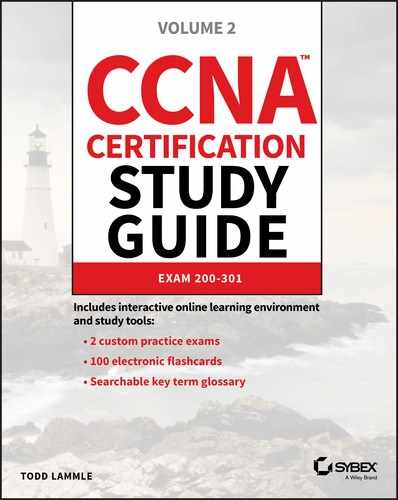
In contrast to the networks of yesterday that were based on collapsed backbones, thanks to switches, today’s network design is characterized by a flatter architecture. So now what? How do we break up broadcast domains in a pure switched internetwork? By creating virtual local area networks (VLANs). A VLAN is a logical grouping of network users and resources connected to administratively defined ports on a switch. When you create VLANs, you’re given the ability to create smaller broadcast domains within a layer 2 switched internetwork by assigning different ports on the switch to service different subnetworks. A VLAN is treated like its own subnet or broadcast domain, meaning that frames broadcast onto the network are only switched between the ports logically grouped within the same VLAN. So, does this mean we no longer need routers? Maybe yes; maybe no. It really depends on what your specific networking needs and goals are. By default, hosts in a specific VLAN can’t communicate with hosts that are members of another VLAN, so if you want inter-VLAN communication, the answer is that you still need a router or Inter-VLAN Routing (IVR). Coming up I’m going to walk you through exactly what a VLAN is and how VLAN memberships are used in a switched networking environment. You’ll learn what a trunk link is, plus how to configure and verify them. Towards the end of this chapter, I’ll demonstrate how inter-VLAN communication works by introducing a router into our switched network. Of course, you’ll be working with the same, switched network layout we used in the last chapter. We’ll create VLANs, implement trunking and configure Inter-VLAN routing on a layer 3 switch by building switched virtual interfaces (SVIs). Figure 8.1 illustrates the flat network architecture that used to be standard for layer 2 switched networks. With this type of configuration, every broadcast packet transmitted is seen by every device on the network regardless of whether the device needs to receive that data or not.
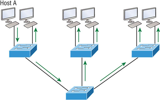
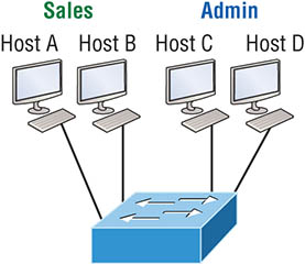
Figure 8.1 Flat network structure By default, routers allow broadcasts to occur only within the originating network, whereas switches forward broadcasts to all segments. The reason it’s called a flat network is because it’s one broadcast domain, not because the actual design is physically flat. In Figure 8.1 we see Host A sending out a broadcast and all ports on all switches forwarding it—all except the port that originally received it. Now check out Figure 8.2. It pictures a switched network and shows Host A sending a frame with Host D as its destination. Clearly, the important factor here is that the frame is only forwarded out the port where Host D is located. Figure 8.2 The benefit of a switched network This is a huge improvement over the old hub networks that only offer one huge collision domain by default! The biggest benefit gained by having a layer 2 switched network is that it creates individual collision domain segments for each device plugged into each port on the switch. It frees us from the old Ethernet density constraints and allows us to build larger networks. But it’s not all sunshine here—the more users and devices that populate and use a network, the more broadcasts and packets each switch has to deal with. And there’s another big downside—security! Rather, the lack thereof because within the typical layer 2 switched internetwork, all users can see all devices by default. And you can’t stop devices from broadcasting, plus you can’t stop users from trying to respond to broadcasts. This means your security options are dismally limited to placing passwords on your servers and other devices. But wait—there’s hope! We can solve a slew of layer 2 switching snags by creating VLANs, as you’ll soon see. VLANs work like this: Figure 8.3 shows all hosts in this very small company connected to one switch. This means all hosts will receive all frames because that’s the default behavior of all switches. Figure 8.3 One switch, one LAN: Before VLANs, there were no separations between hosts. If we want to separate the host’s data, we could either buy another switch or create virtual LANs, as shown in Figure 8.4. Figure 8.4 One switch, two virtual LANs (logical separation between hosts): Still physically one switch, but this switch can act as many separate devices. In Figure 8.4, I configured the switch to be two separate LANs, two subnets, two broadcast domains, two VLANs—they all mean the same thing—without buying another switch. We can do this 1,000 times on most Cisco switches, which saves thousands of dollars and more! Notice that even though the separation is virtual and the hosts are all still connected to the same switch, the LANs can’t send data to each other by default. This is because they are still separate networks. We’ll get into inter-VLAN communication later in this chapter. Here’s a short list of ways VLANs simplify network management:
Next, we’ll explore the world of switching to discover how and why switches provide us with much better network services than hubs can in our networks today. Broadcasts occur in every protocol, but how often they occur depends upon three things:
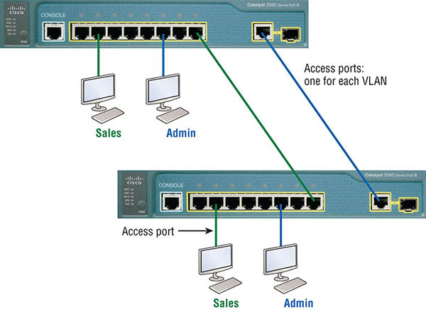
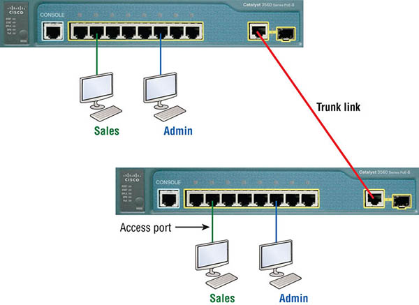
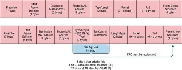
Some older applications have been rewritten to reduce their bandwidth consumption, but the legion of multimedia applications around today consume even generous amounts of bandwidth in no time. Most of these apps use both broadcasts and multicasts extensively. As if that weren’t enough of a challenge, factors like faulty equipment, inadequate segmentation, and poorly designed firewalls can seriously compound the problems already caused by these broadcast-intensive applications. All of this added a major new dimension to network design and presents a bunch of new challenges for an administrator. Positively making sure your network is properly segmented so you can quickly isolate a single segment’s problems to prevent them from propagating throughout your entire internetwork is now imperative. The most effective way to do that is through strategic switching and routing. Since switches have become more affordable, most everyone has replaced their flat hub networks with pure switched network and VLAN environments. All devices within a VLAN are members of the same broadcast domain and receive all broadcasts relevant to it. By default, these broadcasts are filtered from all ports on a switch that aren’t members of the same VLAN. This is wonderful because you get all the benefits you would with a switched design without getting hit with all the problems you’d have if all your users were in the same broadcast domain! But there’s always a catch, right? Time to get back to those security issues. A flat internetwork’s security used to be tackled by connecting hubs and switches together with routers. So it was basically the router’s job to maintain security. This arrangement was pretty ineffective for several reasons. First, anyone connecting to the physical network could access the network resources located on that particular physical LAN. Second, all anyone had to do to observe any and all traffic traversing that network was to simply plug a network analyzer into the hub. And like that last, scary fact, users could easily join a workgroup by just plugging their workstations into the existing hub! But that’s exactly what makes VLANs so cool. If you build them and create multiple broadcast groups, you can still have total control over each port and user. So the days when anyone could just plug their workstations into any switch port and gain access to network resources are history because now you get to control each port and any resources it can access. And that’s not even all—VLANs can be created in harmony with a specific user’s need for the network resources. Plus, switches can be configured to inform a network management station about unauthorized access to those vital network resources. And if you need inter-VLAN communication, you can implement restrictions on a router to make sure this all happens securely. You can also place restrictions on hardware addresses, protocols, and applications. Now we’re talking security! As we know, layer 2 switches only read frames for filtering because they don’t look at the Network layer protocol. And by default, switches forward broadcasts to all ports. But if you create and implement VLANs, you’re essentially creating smaller broadcast domains at layer 2. As a result, broadcasts sent out from a node in one VLAN won’t be forwarded to ports configured to belong to a different VLAN. But if we assign switch ports or users to VLAN groups on a switch or on a group of connected switches, we gain the flexibility to exclusively add only the users we want to let into that broadcast domain regardless of their physical location. This setup can also work to block broadcast storms caused by a faulty network interface card (NIC) as well as prevent an intermediate device from propagating broadcast storms throughout the entire internetwork. Those evils can still happen on the VLAN where the problem originated, but the disease will be fully contained in that one ailing VLAN. Another advantage is that when a VLAN gets too big, you can simply create more VLANs to keep the broadcasts from consuming too much bandwidth. The fewer users in a VLAN, the fewer users affected by broadcasts. This is all good, but you seriously need to keep network services in mind and understand how the users connect to these services when creating a VLAN. A good strategy is to try to keep all services, except for the email and Internet access that everyone needs, local to all users whenever possible. Switch ports are layer 2–only interfaces that are associated with a physical port that can belong to only one VLAN if it’s an access port or all VLANs if it’s a trunk port. Switches are definitely busy devices. As myriad frames are switched throughout the network, they have to be able to keep track of all frames, plus understand what to do with them depending on their associated hardware addresses. And remember—frames are handled differently according to the type of link they’re traversing. There are two different types of ports in a switched environment. Let’s take a look at the first type in Figure 8.5. Figure 8.5 Access ports Notice there are access ports for each host and an access port between switches—one for each VLAN. Access ports An access port belongs to and carries the traffic of only one VLAN. Traffic is both received and sent in native formats with no VLAN information (tagging) at all. Anything arriving on an access port is simply assumed to belong to the VLAN assigned to the port. Because an access port doesn’t look at the source address, tagged traffic—a frame with added VLAN information—can be correctly forwarded and received only on trunk ports. With an access link, this can be referred to as the configured VLAN of the port. Any device attached to an access link is unaware of a VLAN membership—the device just assumes it’s part of some broadcast domain. But it doesn’t have the big picture, so it doesn’t understand the physical network topology at all. Another good bit of information to know is that switches remove any VLAN information from the frame before it’s forwarded out to an access-link device. Remember that access-link devices can’t communicate with devices outside their VLAN unless the packet is routed. Also, you can only create a switch port to be either an access port or a trunk port—not both. So you’ve got to choose one or the other and know that if you make it an access port, that port can be assigned to one VLAN only. In Figure 8.5, only the hosts in the Sales VLAN can talk to other hosts in the same VLAN. This is the same with the Admin VLAN, and they can both communicate to hosts on the other switch because of an access link for each VLAN configured between switches. Voice access ports Not to confuse you, but all that I just said about the fact that an access port can be assigned to only one VLAN is really only sort of true. Nowadays, most switches will allow you to add a second VLAN to an access port on a switch port for your voice traffic, called the voice VLAN. The voice VLAN used to be called the auxiliary VLAN, which allowed it to be overlaid on top of the data VLAN, enabling both types of traffic to travel through the same port. Even though this is technically considered to be a different type of link, it’s still just an access port that can be configured for both data and voice VLANs. This allows you to connect both a phone and a PC device to one switch port but still have each device in a separate VLAN. Trunk ports Believe it or not, the term trunk port was inspired by the telephone system trunks, which carry multiple telephone conversations at a time. So it follows that trunk ports can similarly carry multiple VLANs at a time as well. A trunk link is a 100, 1,000, 10,000 Mbps, or more, point-to-point link between two switches, between a switch and router, or even between a switch and server, and it carries the traffic of multiple VLANs—from 1 to 4,094 VLANs at a time. But the amount is really only up to 1,001 unless you’re going with extended VLANs. Instead of an access link for each VLAN between switches, we’ll create a trunk link as seen in Figure 8.6. Figure 8.6 VLANs can span multiple switches by using trunk links, which carry traffic for multiple VLANs. Trunking can offer a real advantage because with it, you get to make a single port part of a whole bunch of different VLANs at the same time. This is a great feature because you can actually set ports up to have a server in two separate broadcast domains simultaneously so your users won’t have to cross a layer 3 device (router) to log in and access it. Another benefit to trunking comes into play when you’re connecting switches. Trunk links can carry the frames of various VLANs across them, but by default, if the links between your switches aren’t trunked, only information from the configured access VLAN will be switched across that link. Also good to know is that all VLANs send information on a trunked link unless you clear each VLAN by hand. I’ll show you how to clear individual VLANs from a trunk in a bit. It’s finally time to tell you about frame tagging and the VLAN identification methods used in it across our trunk links. As you now know, you can set up your VLANs to span more than one connected switch. You can see that going on in Figure 8.6, which depicts hosts from two VLANs spread across two switches. This flexible, power-packed capability is probably the main advantage to implementing VLANs, and we can do this with up to a thousand VLANs and thousands upon thousands of hosts! All this can get kind of complicated—even for a switch—so there needs to be a way for each one to keep track of all the users and frames as they travel the switch fabric and VLANs. When I say “switch fabric,” I’m just referring to a group of switches that share the same VLAN information. And this just happens to be where frame tagging enters the scene. This frame identification method uniquely assigns a user-defined VLAN ID to each frame. Here’s how it works: Once within the switch fabric, each switch that the frame reaches must first identify the VLAN ID from the frame tag. It then finds out what to do with the frame by looking at the information in what’s known as the filter table. If the frame reaches a switch that has another trunked link, the frame will be forwarded out of the trunk-link port. Once the frame reaches an exit that’s determined by the forward/filter table to be an access link matching the frame’s VLAN ID, the switch will remove the VLAN identifier. This is so the destination device can receive the frames without being required to understand their VLAN identification information. Another great thing about trunk ports is that they’ll support tagged and untagged traffic simultaneously—if you’re using 802.1q trunking, which we will talk about next. The trunk port is assigned a default port VLAN ID (PVID) for a VLAN upon which all untagged traffic will travel. This VLAN is also called the native VLAN and is always VLAN 1 by default, but it can be changed to any VLAN number. Similarly, any untagged or tagged traffic with a NULL (unassigned) VLAN ID is assumed to belong to the VLAN with the port default PVID. Again, this would be VLAN 1 by default. A packet with a VLAN ID equal to the outgoing port native VLAN is sent untagged and can communicate to only hosts or devices in that same VLAN. All other VLAN traffic has to be sent with a VLAN tag to communicate within a particular VLAN that corresponds with that tag. VLAN identification is what switches use to keep track of all those frames as they’re traversing a switch fabric. It’s how switches identify which frames belong to which VLANs, and there’s more than one trunking method. Inter-Switch Link (ISL) is a way of explicitly tagging VLAN information onto an Ethernet frame. This tagging information allows VLANs to be multiplexed over a trunk link through an external encapsulation method. This allows the switch to identify the VLAN membership of a frame received over the trunked link. By running ISL, you can interconnect multiple switches and still maintain VLAN information as traffic travels between switches on trunk links. ISL functions at layer 2 by encapsulating a data frame with a new header and by performing a new cyclic redundancy check (CRC). Of note is that ISL is proprietary to Cisco switches, but it’s pretty versatile too. ISL can be used on a switch port, router interfaces, and server interface cards to trunk a server. Although some Cisco switches still support ISL frame tagging, Cisco has moved toward using only 802.1q. Created by the IEEE as a standard method of frame tagging, IEEE 802.1q actually inserts a field into the frame to identify the VLAN. If you’re trunking between a Cisco switched link and a different brand of switch, you’ve got to use 802.1q for the trunk to work. Unlike ISL, which encapsulates the frame with control information, 802.1q inserts an 802.1q field along with tag control information, as shown in Figure 8.7. Figure 8.7 IEEE 802.1q encapsulation with and without the 802.1q tag For the Cisco exam objectives, it’s only the 12-bit VLAN ID that matters. This field identifies the VLAN and can be 2 to the 12th, minus 2 for the 0, and 4,095 reserved VLANs, which means an 802.1q tagged frame can carry information for 4,094 VLANs. It works like this: You first designate each port that’s going to be a trunk with 802.1q encapsulation. The other ports must be assigned a specific VLAN ID in order for them to communicate. VLAN 1 is the default native VLAN, and when using 802.1q, all traffic for a native VLAN is untagged. The ports that populate the same trunk create a group with this native VLAN, and each port gets tagged with an identification number reflecting that. Again, the default is VLAN 1. The native VLAN allows the trunks to accept information that was received without any VLAN identification or frame tag. Most 2960 model switches only support the IEEE 802.1q trunking protocol. The 3560 will support both the ISL and IEEE methods, which you’ll see later in this chapter. Hosts in a VLAN live in their own broadcast domain and can communicate freely. VLANs create network partitioning and traffic separation at layer 2 of the OSI. As I said when I told you why we still need routers, if you want hosts or any other IP-addressable device to communicate between VLANs, you must have a layer 3 device to provide routing. For this, you can use a router that has an interface for each VLAN or a router that supports ISL or 802.1q routing. The least expensive router that supports ISL or 802.1q routing is the 2600 series router. You’d have to buy that from a used-equipment reseller because they are end-of-life, or EOL. I’d recommend at least a 2800 as a bare minimum, but even that only supports 802.1q; Cisco is really moving away from ISL, so you probably should only be using 802.1q anyway. Some 2800s may support both ISL and 802.1q; I’ve just never seen it supported. Anyway, as shown in Figure 8.8, if you had two or three VLANs, you could get by with a router equipped with two or three FastEthernet connections. And 10Base-T is okay for home study purposes, and I mean only for your studies, but for anything else I’d highly recommend Gigabit or higher interfaces for real power under the hood! What we see in Figure 8.8 is that each router interface is plugged into an access link. This means that each of the routers’ interface IP addresses would then become the default gateway address for each host in each respective VLAN.
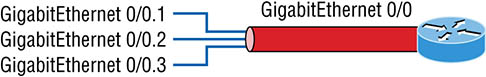
Figure 8.8 Router connecting three VLANs together for inter-VLAN communication, one router interface for each VLAN If you have more VLANs available than router interfaces, you can configure trunking on one FastEthernet interface or buy a layer 3 switch, like the old and now cheap 3560 or a higher-end switch like a 3850. You could even opt for a 6800 if you’re feeling spendy. Instead of using a router interface for each VLAN, you can use one FastEthernet interface and run ISL or 802.1q trunking. Figure 8.9 shows how a FastEthernet interface on a router will look when configured with ISL or 802.1q trunking. This allows all VLANs to communicate through one interface. Cisco calls this a router on a stick (ROAS), and this is what’s used on the CCNA objectives for Inter-VLAN routing. Figure 8.9 Router on a stick: single router interface connecting all three VLANs together for inter-VLAN communication I really want to point out that this creates a potential bottleneck, as well as a single point of failure, so your host/VLAN count is limited. To how many? Well, that depends on your traffic level. To really make things right, you’d be better off using a higher-end switch and routing on the backplane. But if you just happen to have a router sitting around, configuring this method is free, right? Figure 8.10 shows how we would create a router on a stick using a router’s physical interface by creating logical interfaces—one for each VLAN.
Figure 8.10 A router creates logical interfaces. Here we see one physical interface divided into multiple subinterfaces, with one subnet assigned per VLAN, and each subinterface being the default gateway address for each VLAN/subnet. An encapsulation identifier must be assigned to each subinterface to define the VLAN ID of that subinterface. In the next section where I’ll configure VLANs and inter-VLAN routing, I’ll configure our switched network with a router on a stick to demonstrate this for you. But wait, there’s still one more way to go about routing! Instead of using an external router interface for each VLAN or an external router on a stick, we can configure logical interfaces on the backplane of the layer 3 switch; this is called inter-VLAN routing (IVR), and it’s configured with a switched virtual interface (SVI). Figure 8.11 shows how hosts see these virtual interfaces. Figure 8.11 With IVR, routing runs on the backplane of the switch, and it appears to the hosts that a router is present. In Figure 8.11, it appears there’s a router present, but there is no physical router present as there was when we used router on a stick. The IVR process takes little effort, but it’s easy to implement, which makes it very cool! Plus, it’s a lot more efficient for inter-VLAN routing than an external router is. To implement IVR on a multilayer switch, we just need to create logical interfaces in
the switch configuration for each VLAN. We’ll configure this method in a minute, but first let’s take our existing switched network from Chapter 7, “Layer 2 Switching,” add some VLANs, and then we’ll configure VLAN memberships and trunk links between our switches. Configuring VLANs is actually pretty easy. It’s just that figuring out which users you want in each VLAN is not easy, and doing that can eat up a lot of your time. Once you’ve decided on the number of VLANs you want to create and established which users you want belonging to each one, it’s time to bring your first VLAN into the world. To configure VLANs on a Cisco Catalyst switch, use the global config vlan command. In the following example, I’m going to demonstrate how to configure VLANs on the S1 switch by creating three VLANs for three different departments—again, remember that VLAN 1 is the native and management VLAN by default: In this output, you can see that you can create VLANs from 1 to 4094. But this is only mostly true. As I said, VLANs can really only be created up to 1001, and you can’t use, change, rename, or delete VLANs 1 or 1002 through 1005 because they’re reserved. The VLAN numbers above 1005 are called extended VLANs and won’t be saved in the database unless your switch is set to what is called VLAN Trunking Protocol (VTP) transparent mode. You won’t see these VLAN numbers used too often in production. Here’s an example of me attempting to set my S1 switch to VLAN 4000 when my switch is set to VTP server mode (the default VTP mode): After you create the VLANs that you want, you can use the show vlan command to check them out. But notice that, by default, all ports on the switch are in VLAN 1. To change the VLAN associated with a port, you need to go to each interface and specifically tell it which VLAN to be a part of. Once the VLANs are created, verify your configuration with the show vlan command (sh vlan for short): This may seem repetitive, but it’s important, and I want you to remember it: You can’t change, delete, or rename VLAN 1 because it’s the default VLAN, and you just can’t change that—period. It’s also the native VLAN of all switches by default, and Cisco recommends that you use it as your management VLAN. If you’re worried about security issues, then just change the management VLAN. Basically, any ports that aren’t specifically assigned to a different VLAN will be sent down to the native VLAN—VLAN 1. In the preceding S1 output, you can see that ports Fa0/1 through Fa0/14, Fa0/19 through 23, and Gi0/1 and Gi0/2 uplinks are all in VLAN 1. But where are ports 15 through 18? First, understand that the command show vlan only displays access ports, so now that you know what you’re looking at with the show vlan command, where do you think ports Fa15–18 are? That’s right! They are trunked ports. Cisco switches run a proprietary protocol called Dynamic Trunk Protocol (DTP), and if there is a compatible switch connected, they will start trunking automatically, which is precisely where my four ports are. You have to use the show interfaces trunk command to see your trunked ports like this: This output reveals that the VLANs from 1 to 4094 are allowed across the trunk by default. Another helpful command, which is also part of the Cisco exam objectives, is the show interfaces
interface switchport command: The highlighted output shows us the administrative mode of dynamic desirable, that the port is a trunk port, and that DTP was used to negotiate the frame-tagging method of ISL. It also predictably shows that the native VLAN is the default of 1. Now that we can see the VLANs created, we can assign switch ports to specific ones. Each port can be part of only one VLAN, with the exception of voice access ports. Using trunking, you can make a port available to traffic from all VLANs. I’ll cover that next. You configure a port to belong to a VLAN by assigning a membership mode that specifies the kind of traffic the port carries plus the number of VLANs it can belong to. You can also configure each port on a switch to be in a specific VLAN (access port) by using the interface switchport command. You can even configure multiple ports at the same time with the interface range command. In the next example, I’ll configure interface Fa0/3 to VLAN 3. This is the connection from the S3 switch to the host device: Well now, what do we have here? There’s some new stuff showing up in our output now. We can see various commands—some that I’ve already covered, but no worries because I’m going to cover the access, mode, nonegotiate, and trunk commands coming up. However, let’s start with setting an access port on S1, which is probably the most widely used type of port you’ll find on production switches that have VLANs configured: By starting with the switchport mode access command, you’re telling the switch that this is a nontrunking layer 2 port. You can then assign a VLAN to the port with the switchport access command, as well as configure the same port to be a member of a different type of VLAN, called the voice VLAN. This allows you to connect a laptop into a phone, and the phone into a single switch port. Remember, you can choose many ports to configure simultaneously with the interface range command. Let’s take a look at our VLANs now: Notice that port Fa0/3 is now a member of VLAN 3 and VLAN 5—two different types of VLANs. But, can you tell me where ports 1 and 2 are? And why aren’t they showing up in the output of show vlan? That’s right, because they are trunk ports! We can also see this with the show interfaces interface switchport command: Access Mode VLAN: 3 (Marketing) Trunking Native Mode VLAN: 1 (default) Administrative Native VLAN tagging: enabled Voice VLAN: 5 (Voice) The highlighted output shows that Fa0/3 is an access port and a member of VLAN 3 (Marketing), as well as a member of the Voice VLAN 5. That’s it. Well, sort of. If you plugged devices into each VLAN port, they can only talk to other devices in the same VLAN. But as soon as you learn a bit more about trunking, we’re going to enable inter-VLAN communication! The 2960 switch only runs the IEEE 802.1q encapsulation method. To configure trunking on a FastEthernet port, use the interface command switchport mode trunk. It’s a tad different on the 3560 switch. The following switch output shows the trunk configuration on interfaces Fa0/15–18 as set to trunk: I want to point out here that if you have a switch that only runs the 802.1q encapsulation method, you wouldn’t use the encapsulation command as I did in the preceding output. Let’s check out our trunk ports now: Notice that port Fa0/15 is a trunk and running 802.1q. Let’s take another look: Take note of the fact that ports 15–18 are now in the trunk mode of on and the encapsulation is now 802.1q instead of the negotiated ISL. Here’s a description of the different options available when configuring a switch interface: switchport mode access I touched on this in the previous section… It puts the interface (access port) into permanent nontrunking mode and negotiates to convert the link into a nontrunk link. The interface becomes a nontrunk interface regardless of whether the neighboring interface is a trunk interface. The port would be a dedicated layer 2 access port.
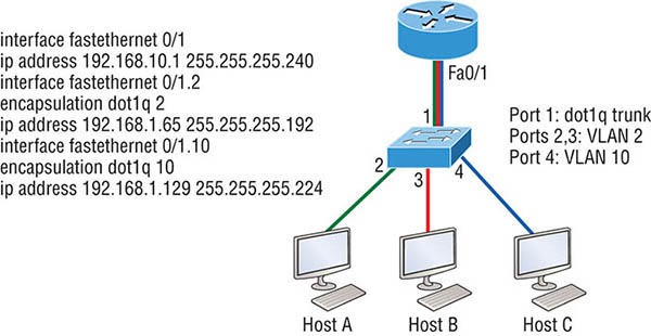
switchport mode dynamic auto This mode makes the interface able to convert the link to a trunk link. The interface becomes a trunk interface if the neighboring interface is set to trunk or desirable mode. The default is dynamic auto on a lot of Cisco switches, but that default trunk method is changing to dynamic desirable on most new models. switchport mode dynamic desirable This one makes the interface actively attempt to convert the link to a trunk link. The interface becomes a trunk interface if the neighboring interface is set to trunk, desirable, or auto mode. I used to see this mode as the default on some switches, but not anymore. It’s now the default switch port mode for all Ethernet interfaces on all new Cisco switches. switchport mode trunk Puts the interface into permanent trunking mode and negotiates to convert the neighboring link into a trunk link. The interface becomes a trunk interface even if the neighboring interface isn’t a trunk interface. switchport nonegotiate Prevents the interface from generating DTP frames. You can use this command only when the interface switchport mode is access or trunk. You must manually configure the neighboring interface as a trunk interface to establish a trunk link. To disable trunking on an interface, use the switchport mode access command, which sets the port back to a dedicated layer 2 access switch port. As I’ve mentioned, trunk ports send and receive information from all VLANs by default, and if a frame is untagged, it’s sent to the management VLAN. Know that this applies to the extended range VLANs too. We can remove VLANs from the allowed list to prevent traffic from certain VLANs from traversing a trunked link. I’ll show you how you’d do that, but first let me again demonstrate that all VLANs are allowed across the trunk link by default: The preceding command affected the trunk link configured on S1 port F0/15, causing it to permit all traffic sent and received for VLANs 4, 6, 12, and 15. You can try to remove VLAN 1 on a trunk link, but it will still send and receive management like CDP, DTP, and VTP, so what’s the point? To remove a range of VLANs, just use the hyphen: If by chance someone has removed some VLANs from a trunk link and you want to set the trunk back to default, just use this command: Next, I want to show you how to configure a native VLAN for a trunk before we start routing between VLANs. You can change the trunk port native VLAN from VLAN 1, which many people do for security reasons. To change the native VLAN, use the following command: So we’ve changed our native VLAN on our trunk link to 4, and by using the show running-config command, I can see the configuration under the trunk link: Oops—wait a minute! You didn’t think it would just start working, did you? Of course not! Here’s the rub: If all switches don’t have the same native VLAN configured on the given trunk links, then we’ll start to receive this error, which happened immediately after I entered the command: Actually, this is a good, noncryptic error, so I can either go to the other end of our trunk link(s) and change the native VLAN or set the native VLAN back to the default to fix it. Here’s how to do that: Okay—now our trunk link is using the default VLAN 1 as the native VLAN. Just remember that all switches on a given trunk must use the same native VLAN or you’ll have some ugly management problems. These issues won’t affect user data, just management traffic between switches. Now, let’s mix it up by connecting a router into our switched network and configure inter-VLAN communication. By default, only hosts that are members of the same VLAN can communicate. To change this and allow inter-VLAN communication, you need a router or a layer 3 switch. I’m going to start with the router approach. To support ISL or 802.1q routing on a FastEthernet interface, the router’s interface is divided into logical interfaces—one for each VLAN—as was shown in Figure 8.10. These are called subinterfaces. From a FastEthernet or Gigabit interface, you can set the interface to trunk with the encapsulation command: Notice that my 2811 router (named ISR) only supports 802.1q. We’d need an older-model router to run the ISL encapsulation, but why bother? The subinterface number is only locally significant, so it doesn’t matter which subinterface numbers are configured on the router. Most of the time, I’ll configure a subinterface with the same number as the VLAN I want to route. It’s easy to remember that way since the subinterface number is used only for administrative purposes. It’s really important that you understand that each VLAN is actually a separate subnet. True, I know—they don’t have to be, but it really is smart to configure your VLANs as separate subnets. Before we move on, I want to define upstream routing. This is a term used to define the router on a stick. This router will provide inter-VLAN routing, but it can also be used to forward traffic upstream from the switched network to other parts of the corporate network or Internet. So let’s make sure you’re fully prepared to configure inter-VLAN routing and that you can determine the IP addresses of hosts connected in a switched VLAN environment. As always, it’s also a good idea to be able to fix any problems that may arise. To set you up for success, let me give you few examples. First, start by looking at Figure 8.12 and read the router and switch configuration within it. By this point in the book, you should be able to determine the IP address, masks, and default gateways of each of the hosts in the VLANs. Figure 8.12 Configuring inter-VLAN example 1 The next step is to figure out which subnets are being used. By looking at the router configuration in the figure, you can see that we’re using 192.168.10.0/28 for VLAN1, 192.168.1.64/26 with VLAN 2, and 192.168.1.128/27 for VLAN 10. By looking at the switch configuration, you can see that ports 2 and 3 are in VLAN 2 and port 4 is in VLAN 10. This means that Host A and Host B are in VLAN 2 and Host C is in VLAN 10. But wait—what’s that IP address doing there under the physical interface? Can we even do that? Sure, we can! If we place an IP address under the physical interface, the result is that frames sent from the IP address would be untagged. So what VLAN would those frames be a member of? By default, they would belong to VLAN 1, our management VLAN. This means the address 192.168.10.1 /28 is my native VLAN IP address for this switch. Here’s what the hosts’ IP addresses should be:
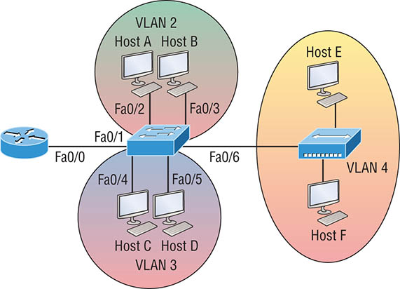
The hosts could be any address in the range—I just chose the first available IP address after the default gateway address. That wasn’t so hard, was it? Now, again using Figure 8.12, let’s go through the commands necessary to configure switch port 1 so it will establish a link with the router and provide inter-VLAN communication using the IEEE version for encapsulation. Keep in mind that the commands can vary slightly depending on what type of switch you’re dealing with. For a 2960 switch, use the following: That’s it! As you already know, the 2960 switch can only run the 802.1q encapsulation, so there’s no need to specify it. You can’t anyway. For a 3560, it’s basically the same, but because it can run ISL and 802.1q, you have to specify the trunking encapsulation protocol you’re going to use. Let’s take a look at Figure 8.13 and see what we can determine. This figure shows three VLANs, with two hosts in each of them. The router in Figure 8.13 is connected to the Fa0/1 switch port, and VLAN 4 is configured on port F0/6. When looking at this diagram, keep in mind that these three factors are what Cisco expects you to know:
Figure 8.13 Inter-VLAN example 2 The configuration of the switch would look something like this: Before we configure the router, we need to design our logical network:
The configuration of the router would then look like this: Notice I didn’t tag VLAN 1. Even though I could have created a subinterface and tagged VLAN 1, it’s not necessary with 802.1q because untagged frames are members of the native VLAN. The hosts in each VLAN would be assigned an address from their subnet range, and the default gateway would be the IP address assigned to the router’s subinterface in
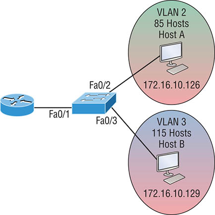
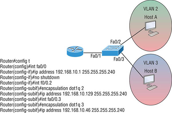
that VLAN. Now, let’s take a look at another figure and see if you can determine the switch and router configurations without looking at the answer—no cheating! Figure 8.14 shows a router connected to a 2960 switch with two VLANs. One host in each VLAN is assigned an IP address. What would your router and switch configurations be based on these IP addresses? Figure 8.14 Inter-VLAN example 3 Since the hosts don’t list a subnet mask, you have to look for the number of hosts used in each VLAN to figure out the block size. VLAN 2 has 85 hosts, and VLAN 3 has 115 hosts. Each of these will fit in a block size of 128, which is a /25 mask, or 255.255.255.128. You should know by now that the subnets are 0 and 128; the 0 subnet (VLAN 2) has a host range of 1–126, and the 128 subnet (VLAN 3) has a range of 129–254. You can almost be fooled since Host A has an IP address of 126, which makes it almost seem that Host A and B are in the same subnet. But they’re not, and you’re way too smart by now to be fooled by this one, right? Here’s the switch configuration: Here’s the router configuration: I used the first address in the host range for VLAN 2 and the last address in the range for VLAN 3, but any address in the range would work. You would just have to configure the host’s default gateway to whatever you make the router’s address. Also, I used a different subnet for my physical interface, which is my management VLAN router’s address. Before we go on to the next example, let’s make sure you know how to set the IP address on the switch. Since VLAN 1 is typically the administrative VLAN, we’ll use an IP address from out of that pool of addresses. Here’s how to set the IP address of the switch (not nagging, but you really should know this already!): Yes, you have to execute a no shutdown on the VLAN interface and set the ip default-gateway address to the router. One more example, and then we’ll move on to IVR using a multilayer switch—another important subject that you definitely don’t want to miss. In Figure 8.15 there are two VLANs, plus the management VLAN 1. By looking at the router configuration, what’s the IP address, subnet mask, and default gateway of Host A? Use the last IP address in the range for Host A’s address. If you look really carefully at the router configuration (the hostname in this configuration is just Router), there’s a simple and quick answer. All subnets are using a /28, which is a 255.255.255.240 mask. This is a block size of 16. The router’s address for VLAN 2 is in subnet 128. The next subnet is 144, so the broadcast address of VLAN 2 is 143 and the valid host range is 129–142. So the host address would be this:
This section was probably the hardest part of this book so far, and I honestly created the simplest configuration you can possibly get away with using to help you through it! I’ll use Figure 8.16 to demonstrate configuring inter-VLAN routing (IVR) with a multilayer switch, using interface fa0/0, which is often referred to as a switched virtual interface (SVI). I’m going to use the same network that I used to discuss a multilayer switch back in Figure 8.11, and I’ll use this IP address scheme: 192.168.x.0/24, where x represents the VLAN subnet. In my example this will be the same as the VLAN number.
Figure 8.15 Inter-VLAN example 4 Figure 8.16 Inter-VLAN routing with a multilayer switch The hosts are already configured with the IP address, subnet mask, and default gateway address using the first address in the range. Now I just need to configure the routing on the switch, which is pretty simple actually: And that’s it! Enable IP routing and create one logical interface for each VLAN using the interface vlan number command and voilà! You’ve now accomplished making inter-VLAN routing work on the backplane of the switch. This chapter introduced you to the world of virtual LANs and described how Cisco switches can use them. We talked about how VLANs break up broadcast domains in a switched internetwork. This is a very important thing because layer 2 switches only break up collision domains, and by default, all switches make up one large broadcast domain. I also described access links to you, and we went over how trunked VLANs work across a FastEthernet or faster link. Trunking is a crucial technology to understand really well when you’re dealing with a network populated by multiple switches that are running several VLANs. You were also presented with some key troubleshooting and configuration examples for access and trunk ports, configuring trunking options, and a huge section on IVR. Understand the term
frame tagging. Frame tagging refers to VLAN identification; this is what switches use to keep track of all those frames as they’re traversing a switch fabric. It’s how switches identify which frames belong to which VLANs. Understand the 802.1q VLAN identification method. This is a nonproprietary IEEE method of frame tagging. If you’re trunking between a Cisco switched link and a different brand of switch, you have to use 802.1q for the trunk to work. Remember how to set a trunk port on a 2960 switch. To set a port to trunking on a 2960, use the switchport mode trunk command. Remember to check a switch port’s VLAN assignment when plugging in a new host. If you plug a new host into a switch, then you must verify the VLAN membership of that port. If the membership is different than what is needed for that host, the host will not be able to reach the needed network services, such as a workgroup server or printer. Remember how to create a Cisco router on a stick to provide inter-VLAN communication.
You can use a Cisco FastEthernet or Gigabit Ethernet interface to provide inter-VLAN routing. The switch port connected to the router must be a trunk port; then you must create virtual interfaces (subinterfaces) on the router port for each VLAN connecting to it. The hosts in each VLAN will use this subinterface address as their default gateway address. Remember how to provide inter-VLAN routing with a layer 3 switch. You can use a layer 3 (multilayer) switch to provide IVR just as with a router on a stick, but using a layer 3 switch is more efficient and faster. First you start the routing process with the command ip routing, then create a virtual interface for each VLAN using the command interface vlan vlan, and then apply the IP address for that VLAN under that logical interface. You can find the answers to these questions in the Appendix. Which of the following statements is true with regard to VLANs?
You can only add one data VLAN to a switch port when configured as an Access port. What is the second type of VLAN that can be added to an Access port?
In the following configuration, what command is missing in the creation of the VLAN interface?
Which of the following statements is true with regard to ISL and 802.1q?
Based on the configuration shown here, what statement is true?
What is true of the output shown here?
802.1q untagged frames are members of which VLAN.
In the switch output of question 6 how many broadcast domains are shown?
What is the purpose of frame tagging in virtual LAN (VLAN) configurations?
Which statement is true regarding 802.1q frame tagging?
![]() 2.1 Configure and verify VLANs (normal range) spanning multiple switches
2.1 Configure and verify VLANs (normal range) spanning multiple switches
![]() 2.2 Configure and verify interswitch connectivity
2.2 Configure and verify interswitch connectivity
 By default, switches break up collision domains, and routers break up broadcast domains.
![]() To find your included bonus material, as well as Todd Lammle videos, practice questions & hands-on labs, please see www.lammle.com/ccna
To find your included bonus material, as well as Todd Lammle videos, practice questions & hands-on labs, please see www.lammle.com/ccnaVLAN Basics

Broadcast Control
Security
Flexibility and Scalability
Identifying VLANs
Frame Tagging
VLAN Identification Methods
Inter-Switch Link (ISL)
IEEE 802.1q
![]() The basic purpose of ISL and 802.1q frame-tagging methods is to provide inter-switch VLAN communication. Remember that any ISL or 802.1q frame tagging is removed if a frame is forwarded out an access link—tagging is used internally and across trunk links only!
The basic purpose of ISL and 802.1q frame-tagging methods is to provide inter-switch VLAN communication. Remember that any ISL or 802.1q frame tagging is removed if a frame is forwarded out an access link—tagging is used internally and across trunk links only!Routing Between VLANs


Configuring VLANs
S1(config)#vlan ?
WORD ISL VLAN IDs 1-4094
access-map Create vlan access-map or enter vlan access-map command mode
dot1q dot1q parameters
filter Apply a VLAN Map
group Create a vlan group
internal internal VLAN
S1(config)#vlan 2
S1(config-vlan)#name Sales
S1(config-vlan)#vlan 3
S1(config-vlan)#name Marketing
S1(config-vlan)#vlan 4
S1(config-vlan)#name Accounting
S1(config-vlan)#vlan 5
S1(config-vlan)#name Voice
S1(config-vlan)#^Z
S1#
S1#config t
S1(config)#vlan 4000
S1(config-vlan)#^Z
% Failed to create VLANs 4000
Extended VLAN(s) not allowed in current VTP mode.
%Failed to commit extended VLAN(s) changes.
![]() Remember that a created VLAN is unused until it is assigned to a switch port or ports and that all ports are always assigned in VLAN 1 unless set otherwise.
Remember that a created VLAN is unused until it is assigned to a switch port or ports and that all ports are always assigned in VLAN 1 unless set otherwise.S1#sh vlan
VLAN Name Status Ports
---- ------------------------- --------- -------------------------------
1 default active Fa0/1, Fa0/2, Fa0/3, Fa0/4
Fa0/5, Fa0/6, Fa0/7, Fa0/8
Fa0/9, Fa0/10, Fa0/11, Fa0/12
Fa0/13, Fa0/14, Fa0/19, Fa0/20
Fa0/21, Fa0/22, Fa0/23, Gi0/1
Gi0/2
2 Sales active
3 Marketing active
4 Accounting active5 Voice active
[output cut]
S1#
show interfaces trunk
Port Mode Encapsulation Status Native vlan
Fa0/15 desirable n-isl trunking 1
Fa0/16 desirable n-isl trunking 1
Fa0/17 desirable n-isl trunking 1
Fa0/18 desirable n-isl trunking 1
Port Vlans allowed on trunk
Fa0/15 1-4094
Fa0/16 1-4094
Fa0/17 1-4094
Fa0/18 1-4094
[output cut]
S1#sh interfaces fastEthernet 0/15 switchport
Name: Fa0/15
Switchport: Enabled
Administrative Mode: dynamic desirable
Operational Mode: trunk
Administrative Trunking Encapsulation: negotiate
Operational Trunking Encapsulation: isl
Negotiation of Trunking: On
Access Mode VLAN: 1 (default)
Trunking Native Mode VLAN: 1 (default)
Administrative Native VLAN tagging: enabled
Voice VLAN: none
[output cut]
Assigning Switch Ports to VLANs
S3#config t
S3(config)#int fa0/3
S3(config-if)#switchport ?
access Set access mode characteristics of the interface
autostate Include or exclude this port from vlan link up calculation
backup Set backup for the interface
block Disable forwarding of unknown uni/multi cast addresses
host Set port host
mode Set trunking mode of the interface
nonegotiate Device will not engage in negotiation protocol on this
interface
port-security Security related command
priority Set appliance 802.1p priority
private-vlan Set the private VLAN configuration
protected Configure an interface to be a protected port
trunk Set trunking characteristics of the interface
voice Voice appliance attributes voice
S3(config-if)#switchport mode ?
access Set trunking mode to ACCESS unconditionally
dot1q-tunnel set trunking mode to TUNNEL unconditionally
dynamic Set trunking mode to dynamically negotiate access or trunk mode
private-vlan Set private-vlan mode
trunk Set trunking mode to TRUNK unconditionally
S3(config-if)#switchport mode access
S3(config-if)#switchport access vlan 3
S3(config-if)#switchport voice vlan 5
S3#show vlan
VLAN Name Status Ports
---- ------------------------ --------- -------------------------------
1 default active Fa0/4, Fa0/5, Fa0/6, Fa0/7
Fa0/8, Fa0/9, Fa0/10, Fa0/11,
Fa0/12, Fa0/13, Fa0/14, Fa0/19,
Fa0/20, Fa0/21, Fa0/22, Fa0/23,
Gi0/1 ,Gi0/2
2 Sales active
3 Marketing active Fa0/3 5 Voice active Fa0/3
S3#sh int fa0/3 switchport
Name: Fa0/3
Switchport: Enabled
Administrative Mode: static access
Operational Mode: static access
Administrative Trunking Encapsulation: negotiate
Negotiation of Trunking: Off
Configuring Trunk Ports
S1(config)#int range f0/15-18
S1(config-if-range)#switchport trunk encapsulation dot1q
S1(config-if-range)#switchport mode trunk
S1(config-if-range)#do sh int f0/15 swi
Name: Fa0/15
Switchport: Enabled
Administrative Mode: trunk

Operational Mode: trunk

Administrative Trunking Encapsulation: dot1q
Operational Trunking Encapsulation: dot1q
Negotiation of Trunking: On
Access Mode VLAN: 1 (default)
Trunking Native Mode VLAN: 1 (default)
Administrative Native VLAN tagging: enabled
Voice VLAN: none
S1(config-if-range)#do sh int trunk
Port Mode Encapsulation Status Native vlan
Fa0/15 on 802.1q trunking 1
Fa0/16 on 802.1q trunking 1
Fa0/17 on 802.1q trunking 1
Fa0/18 on 802.1q trunking 1
Port Vlans allowed on trunk
Fa0/15 1-4094
Fa0/16 1-4094
Fa0/17 1-4094
Fa0/18 1-4094
![]() Dynamic Trunking Protocol (DTP) is used for negotiating trunking on a link between two devices as well as negotiating the encapsulation type of either 802.1q or ISL. I use the nonegotiate command when I want dedicated trunk ports; no questions asked.
Dynamic Trunking Protocol (DTP) is used for negotiating trunking on a link between two devices as well as negotiating the encapsulation type of either 802.1q or ISL. I use the nonegotiate command when I want dedicated trunk ports; no questions asked.Defining the Allowed VLANs on a Trunk
S1#sh int trunk
[output cut]
Port Vlans allowed on trunk
Fa0/15 1-4094
Fa0/16 1-4094
Fa0/17 1-4094
Fa0/18 1-4094
S1(config)#int f0/15
S1(config-if)#switchport trunk allowed vlan 4,6,12,15
S1(config-if)#do show int trunk
[output cut]
Port Vlans allowed on trunk
Fa0/15 4,6,12,15
Fa0/16 1-4094
Fa0/17 1-4094
Fa0/18 1-4094
S1(config-if)#switchport trunk allowed vlan remove 4-8
S1(config-if)#switchport trunk allowed vlan all
Changing or Modifying the Trunk Native VLAN
S1(config)#int f0/15
S1(config-if)#switchport trunk native vlan ?
<1-4094> VLAN ID of the native VLAN when this port is in trunking mode
S1(config-if)#switchport trunk native vlan 4
1w6d: %CDP-4-NATIVE_VLAN_MISMATCH: Native VLAN mismatch discovered on FastEthernet0/15 (4), with S3 FastEthernet0/1 (1).
S1#sh run int f0/15
Building configuration...
Current configuration : 202 bytes
!
interface FastEthernet0/15
description 1st connection to S3
switchport trunk encapsulation dot1q
switchport trunk native vlan 4
switchport trunk allowed vlan 4,6,12,15
switchport mode trunk
end
S1#!
1w6d: %CDP-4-NATIVE_VLAN_MISMATCH: Native VLAN mismatch discovered
on FastEthernet0/15 (4), with S3 FastEthernet0/1 (1).
S1(config-if)#no switchport trunk native vlan
1w6d: %SPANTREE-2-UNBLOCK_CONSIST_PORT: Unblocking FastEthernet0/15
on VLAN0004. Port consistency restored.
Configuring Inter-VLAN Routing
ISR#config t
ISR(config)#int f0/0.1
ISR(config-subif)#encapsulation ?
dot1Q IEEE 802.1Q Virtual LAN
ISR(config-subif)#encapsulation dot1Q ?
<1-4094> IEEE 802.1Q VLAN ID
2960#config t
2960(config)#interface fa0/1
2960(config-if)#switchport mode trunk
![]() Remember that when you create a trunked link, all VLANs are allowed to pass data by default.
Remember that when you create a trunked link, all VLANs are allowed to pass data by default.
2960#config t
2960(config)#int f0/1
2960(config-if)#switchport mode trunk
2960(config-if)#int f0/2
2960(config-if)#switchport access vlan 2
2960(config-if)#int f0/3
2960(config-if)#switchport access vlan 2
2960(config-if)#int f0/4
2960(config-if)#switchport access vlan 3
2960(config-if)#int f0/5
2960(config-if)#switchport access vlan 3
2960(config-if)#int f0/6
2960(config-if)#switchport access vlan 4
ISR#config t
ISR(config)#int fa0/0
ISR(config-if)#ip address 192.168.10.1 255.255.255.240
ISR(config-if)#no shutdown
ISR(config-if)#int f0/0.2
ISR(config-subif)#encapsulation dot1q 2
ISR(config-subif)#ip address 192.168.10.17 255.255.255.240
ISR(config-subif)#int f0/0.3
ISR(config-subif)#encapsulation dot1q 3
ISR(config-subif)#ip address 192.168.10.33 255.255.255.240
ISR(config-subif)#int f0/0.4
ISR(config-subif)#encapsulation dot1q 4
ISR(config-subif)#ip address 192.168.10.49 255.255.255.240
2960#config t
2960(config)#int f0/1
2960(config-if)#switchport mode trunk
2960(config-if)#int f0/2
2960(config-if)#switchport access vlan 2
2960(config-if)#int f0/3
2960(config-if)#switchport access vlan 3
ISR#config t
ISR(config)#int f0/0
ISR(config-if)#ip address 192.168.10.1 255.255.255.0
ISR(config-if)#no shutdown
ISR(config-if)#int f0/0.2
ISR(config-subif)#encapsulation dot1q 2
ISR(config-subif)#ip address 172.16.10.1 255.255.255.128
ISR(config-subif)#int f0/0.3
ISR(config-subif)#encapsulation dot1q 3
ISR(config-subif)#ip address 172.16.10.254 255.255.255.128
2960#config t
2960(config)#int vlan 1
2960(config-if)#ip address 192.168.10.2 255.255.255.0
2960(config-if)#no shutdown
2960(config-if)#exit
2960(config)#ip default-gateway 192.168.10.1
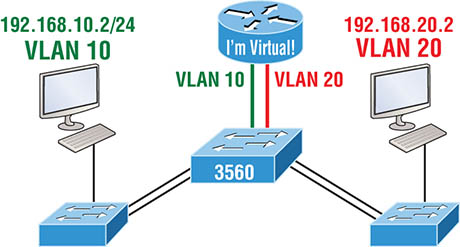
S1(config)#ip routing
S1(config)#int vlan 10
S1(config-if)#ip address 192.168.10.1 255.255.255.0
S1(config-if)#int vlan 20
S1(config-if)#ip address 192.168.20.1 255.255.255.0
Summary
Exam Essentials
Review Questions