
2
VLAN Review
CERTIFICATION OBJECTIVES
Layer 2 devices, including bridges and switches, always propagate certain kinds of traffic in the broadcast domain: broadcasts, multicasts, and unknown destination traffic. This process affects every machine in the broadcast domain (layer 2 network). It affects the bandwidth of these devices’ connections as well as their local processing. If you were using bridges, the only solution available to solve this problem would be to break up the broadcast domain into multiple broadcast domains and interconnect these domains with a router. With this approach, each new broadcast domain would be a new logical segment and would need a unique network number to differentiate it from the other layer 3 logical segments.
Unfortunately, this is a costly solution, since each broadcast domain, each logical segment, needs its own port on a router. The more broadcast domains that you have from bridges, the bigger the router required: an interface for each broadcast domain. As you will see in this chapter, switches also have the same problem with traffic that must be flooded. You will see, however, that switches have a unique solution to reduce the number of router ports required and thus the cost of the layer 3 device that you need to obtain: virtual LANs and trunking.
CERTIFICATION OBJECTIVE 2.01
VLAN Overview
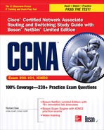
A virtual LAN (VLAN) is a logical grouping of network devices in the same broadcast domain that can span multiple physical segments. The top part of Figure 2-1 shows an example of a simple VLAN, where every device is in both the same collision and broadcast domains. In this example, a hub is providing the connectivity, which represents to the devices connected to it, that the segment is a logical segment.
FIGURE 2-1 VLAN examples
The bottom part of Figure 2-1 shows an example of a switch with four PCs connected to it. One major difference between the switch and the hub is that all devices connected to the hub are in the same collision domain, whereas in the switch example, each port of the switch is a separate collision domain. By default, all ports on a switch are in the same broadcast domain. In this example, however, the configuration of the switch places PC-E and PC-F in one broadcast domain (VLAN) and PC-G and PC-H in another broadcast domain.
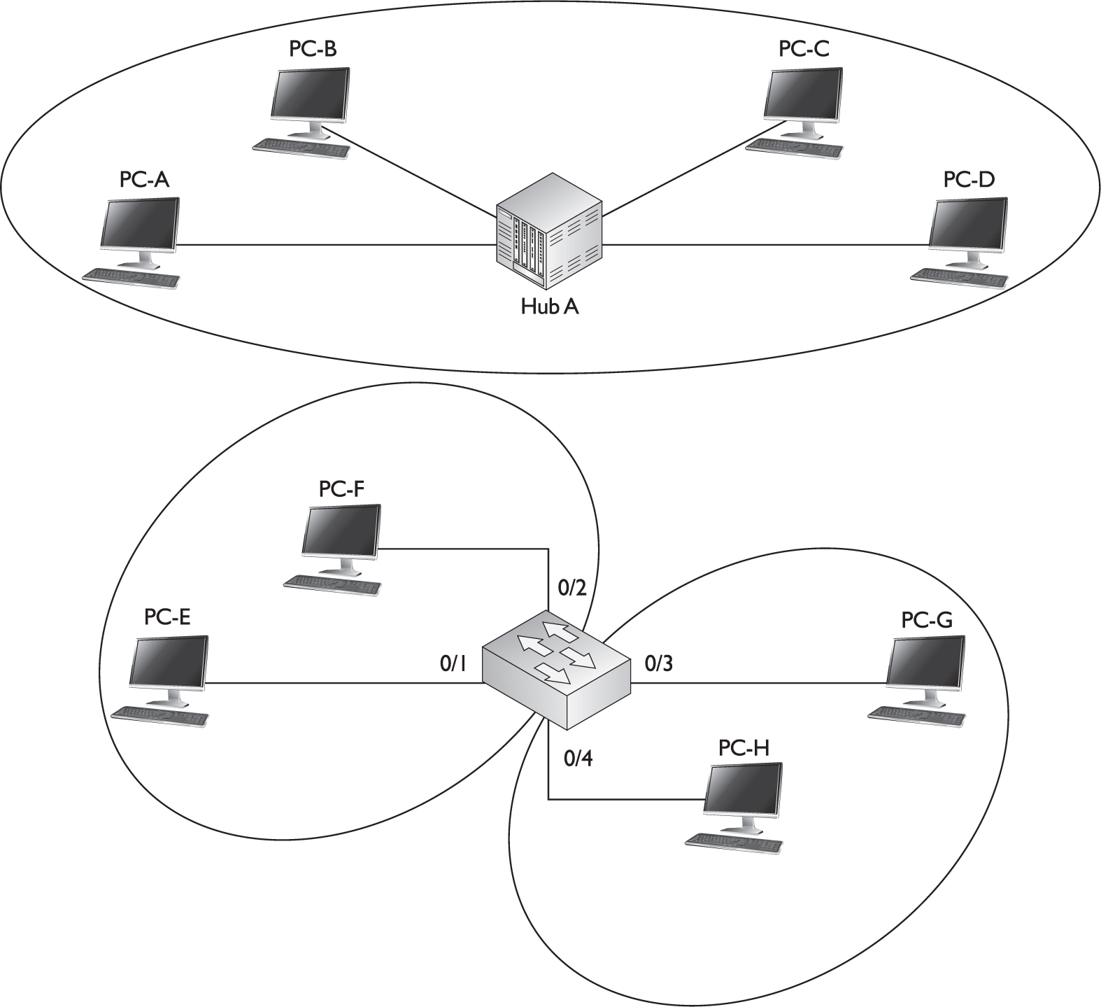
FIGURE 2-2 Physical switched topology using VLANs
Switches are used to create VLANs, or separate broadcast domains. VLANs are not restricted to any physical boundary in the switched network, assuming that all the devices are interconnected via switches and that there are no intervening layer 3 devices. For example, a VLAN could be spread across multiple switches, or it could be contained in the same switch, as is shown in Figure 2-2. This example shows three VLANs. Notice that VLANs are not tied to any physical location: PC-A, PC-B, PC-E, and PC-F are in the same VLAN but are connected to different ports of different switches. However, a VLAN could be contained to one switch, as PC-C and PC-D are connected to SwitchA.
The switches in your network maintain the integrity of your VLANs. For example, if PC-A generates a broadcast, SwitchA and SwitchB will make sure that only other devices in that VLAN (PC-B, PC-E, and PC-F) will see the broadcast and that other devices will not, and that holds true even across switches, as is the case in Figure 2-2.

A VLAN is a group of devices in the same broadcast domain or subnet. VLANs are good at logically separating/segmenting traffic between different groups of users. VLANs contain/isolate broadcast traffic, where you need a router to move traffic between VLANs. VLANs create separate broadcast domains: they increase the number of broadcast domains, but decrease the size of the broadcast domains.
Subnets and VLANs
Logically speaking, VLANs are also subnets. A subnet, or a network, is a contained broadcast domain. A broadcast that occurs in one subnet will not be forwarded, by default, to another subnet. Routers, or layer 3 devices, provide this boundary function. Each of these subnets requires a unique network number. And to move from one network number to another, you need a router. In the case of broadcast domains and switches, each of these separate broadcast domains is a separate VLAN; therefore, you still need a routing function to move traffic between different VLANs.
Remember that each VLAN must be associated with a unique subnet or network number.
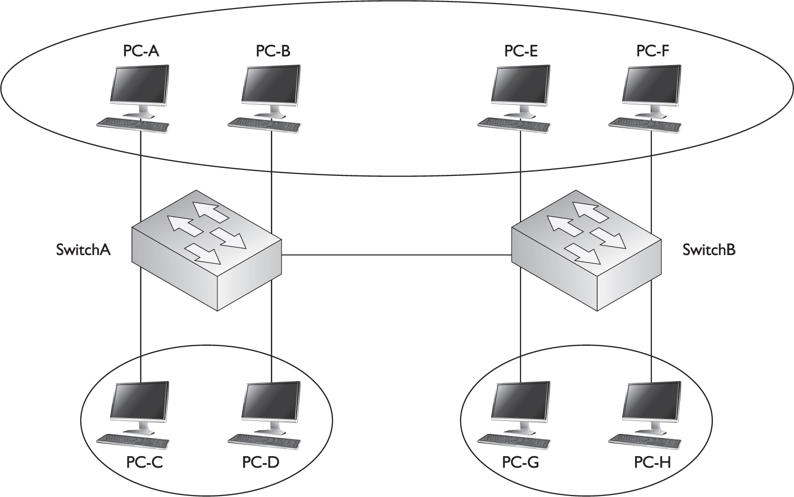
From the user’s perspective, the physical topology shown in Figure 2-2 would actually look like Figure 2-3. And from the user’s perspective, the devices know that to reach another VLAN (subnet), they must forward their traffic to the default gateway address in their VLAN—the IP address on their router’s interface.
FIGURE 2-3 Logical topology using VLANs

One advantage that switches have over bridges, though, is that in a switched VLAN network, assuming your routing function supports VLANs, the switch can handle multiple VLANs on a single port, and a router can route between these VLANs on the same single port. This special kind of connection is called a trunk and is discussed in more depth later in the “VLAN Connections” section. With a bridge, each VLAN must be placed on a separate port of a router, increasing the cost of your routing solution.
Cisco has recommendations as to the number of devices in a VLAN, which are shown in Table 2-1. Remember that these numbers are only recommendations from Cisco; however, they are backed by many years of designing and implementing networks.
TABLE 2-1 Recommendations for Number of Devices in a VLAN


Remember that the information listed in Table 2-1 represents recommendations only: every network and its components are unique. Each network has its own unique characteristics. I once saw a broadcast domain that had almost 1000 devices in it; it worked, but very poorly.
Scalability
Through segmentation of broadcast domains, VLANs increase your network’s scalability. Since VLANs are a logical construct, a user can be located anywhere in the switched network and still belong to the same broadcast domain. If you move a user from one switch to another switch in the same switched network, you can still keep the user in his or her original VLAN. This includes a move from one floor of a building to another floor, or from one part of the campus to another. The limitation is that the user, when moved, must still be connected to the same layer 2 network.
VLANs provide for location independence in a switched network: many logical networks can use the same network infrastructure. This flexibility makes adds, changes, and moves of networking devices a simple process. It also allows you to group people together, perhaps according to their job function, which makes implementing your security policies easier. Logically separating people using VLANs provides additional security, since traffic must traverse a layer 3 device to go from one VLAN to another, where you can use an access control list to filter traffic. Broadcast storms can be mitigated by decreasing the number of broadcast domains, thus increasing the network’s size.
VLANs and Traffic Types
Many network administrators use VLANs not only to separate different types of user traffic (commonly separated by job function), but also to separate it based on the type of traffic, placing network management, multicast, and voice over IP (VoIP) traffic into their own distinctive VLANs.
Network management traffic includes Simple Network Management Protocol (SNMP); Remote Monitoring (RMON); Spanning Tree Protocol (STP); Bridge Protocol Data Units (BPDUs), discussed in Chapter 3; Cisco Discovery Protocol (CDP) messages, discussed in Chapter 7; syslog messages, discussed in Chapter 8; Network Time Protocol (NTP) updates, discussed in Chapter 8; configuration backups of network devices, discussed in Chapter 7; and network device operating system upgrades, discussed in Chapter 7.
Multicast traffic is commonly used by video applications to transmit video streams intelligently from a server to one or more clients interested in seeing it, where UDP is used as a transport for the video stream. An example of a video solution that uses multicasts is Cisco’s IP/TV server. Video traffic is delay sensitive—too much delay can be noticeable by the end user, where the actual video picture looks jumpy and jagged. By separating this traffic from other types through VLANs, and by setting up the necessary quality of service (QoS) for this VLAN traffic, you can help minimize or prevent delay issues.
VoIP traffic includes two kinds of traffic: signaling information sent from the VoIP phones to the VoIP gateway products, such as Cisco Unified Communications Manager (formerly called Cisco CallManager), and the actual voice conversations, which use UDP as a transport between VoIP phones and/or digital phones connected to VoIP PBXs. One issue with VoIP traffic is that it is delay-sensitive, so mixing this kind of traffic with other data types can cause performance issues that are very noticeable on voice connections; separating this traffic in its own VLAN and using QoS to ensure that this kind of traffic is given higher priority than other types is an important design consideration. Some Cisco Catalyst switches support a special type of VLAN, called a voice VLAN. With the voice VLAN feature, switches will automatically place a Cisco VoIP phone into the voice VLAN once the VoIP phone is plugged into the switch. The advantage of this approach is that you, as an administrator, no longer have to worry when a VoIP phone is added to the network about configuring the switch to place the phone into the correct VLAN.
Different data types, such as delay-sensitive voice or video (multicast), network management, and data application traffic, should be separated into different VLANs via connected switches to prevent problems in one data type from affecting others. QoS can be used to prioritize traffic types like VoIP and video to ensure that they receive the necessary bandwidth and are prioritized over other types of data traffic.
VLAN Membership
A device’s membership in a VLAN can be determined by one of three methods: static, dynamic, or voice. These methods affect how a switch will associate a port in its chassis with a particular VLAN. When you are dealing with static VLANs, you must manually assign a port on a switch to a VLAN using an Interface Subconfiguration mode command. VLANs configured in this way are typically called port-based VLANs.
With dynamic VLANs, the switch automatically assigns the port to a VLAN using information from the user device, such as its MAC address, IP address, or even directory information (a user or group name, for instance). The switch then consults a policy server, called a VLAN membership policy server (VMPS), which contains a mapping of device information to VLANs. One of the switches in your network must be configured as this server. Low-end Cisco switches cannot serve as a VMPS server switch, but other switches, such as the Catalyst 6500, can. In this situation, the low-end switches act as clients and use the 6500 to store the dynamic VLAN membership information.
Another option is to use 802.1X authentication, which is used to authenticate a device’s access to a switch or wireless access point. The authentication credentials are stored on an authentication server. One policy you can assign the user account (associated with the authenticating device) on the authentication server is the VLAN to which the device belongs—the server can pass this to the layer 2 device, which, in turn, can associate the VLAN to the port with which the authenticated device is associated.
Dynamic VLANs have one main advantage over static VLANs: they support plug-and-play movability. For instance, if you move a PC from a port on one switch to a port on another switch and you are using dynamic VLANs, the new switch port will automatically be configured for the VLAN to which the user belongs. About the only time that you have to configure information with dynamic VLANs is if you hire an employee and the employee leaves the company or changes job functions.
If you are using static VLANs, not only will you have to configure the switch port manually with this updated information, but, if you move the user from one switch to another, you will also have to perform this manual configuration to reflect the user’s new port. One advantage, though, that static VLANs have over dynamic VLANs is that the configuration process is easy and straightforward. Dynamic VLANs require a lot of initial preparation involving matching users to VLANs. (This book focuses exclusively on static VLANs, as dynamic VLANs are beyond the book’s scope.)
Voice VLANs are unique. They are associated to ports that have VoIP phones attached. Some VoIP phones might have a multiport switch attached to them to allow other devices to connect to the switch via the phone. In this instance, the phone might tag frames to indicate which device is sending the traffic—phone or computer—so that the switch can then deal with the traffic correctly.
CERTIFICATION OBJECTIVE 2.02
VLAN Connections
When dealing with VLANs, switches support two types of switch ports: access links and trunks. When setting up your switches, you will need to know what type of connection an interface should use and configure it appropriately. As you will see, the configuration process for each type of interface is different. This section discusses the two types of connections.
Access Link Connections
An access link connection is a connection to a device that has a standardized Ethernet NIC that understands only standardized Ethernet frames—in other words, a normal NIC that understands IEEE 802.3 and Ethernet II frames. Access link connections can be associated only with a single VLAN (voice VLAN ports are an exception to this). This means that any device or devices connected to this port will be in the same broadcast domain.
For example, if ten users are connected to a hub, and you plug the hub into an access link interface on a switch, then all of these users will belong to the same VLAN that is associated with the switch port. If you wanted five users on the hub to belong to one VLAN and the other five to a different VLAN, you would need to purchase an additional hub and plug each hub into a different switch port. Then, on the switch, you would need to configure each of these ports with the correct VLAN identifier.
An access link connection is a connection between a switch and a device with a normal Ethernet NIC, where the Ethernet frames are transmitted unaltered (untagged). An access link connection normally can be associated only with a single VLAN. If an access link connects two switches, only the VLAN associated with that link will be able to transmit traffic: other VLANs will not be able to send traffic across this link.
Trunk Connections
Unlike access link connections, trunk connections are capable of carrying traffic for multiple VLANs. To support trunking, the original Ethernet frame must be modified to carry VLAN information, commonly called a VLAN identifier or number. This ensures that the broadcast integrity is maintained. For instance, if a device from VLAN 1 has generated a broadcast and the connected switch has received it, when this switch forwards it to other switches, these switches need to know the VLAN origin so that they can forward this frame out only VLAN 1 ports and not other VLAN ports.
Cisco supports two Ethernet trunking methods:
![]() Cisco’s proprietary InterSwitch Link (ISL) protocol for Ethernet
Cisco’s proprietary InterSwitch Link (ISL) protocol for Ethernet
![]() IEEE’s 802.1Q, commonly referred to as dot1q for Ethernet
IEEE’s 802.1Q, commonly referred to as dot1q for Ethernet
A trunk modifies the original frame to carry VLAN information, including a VLAN identifier in the frame. 802.1Q defines a standard method of VLAN trunking. A trunk connection between two switches allows the same VLANs on the two switches to intercommunicate (like VLAN 2 devices on both switches).
Cisco’s high-end switches, such as the Catalyst 6500s, support both types; however, Cisco’s low-end switches support only 802.1Q: ISL is being phased out by Cisco. This book focuses on the use of the latter trunk method, dot1q.
Trunk Tagging
Trunking methods create the illusion that instead of a single physical connection between the two trunking devices, a separate logical connection exists for each VLAN between them. When trunking, the switch adds the source port’s VLAN identifier to the frame so that the device (typically a switch) at the other end of the trunk understands what VLAN originated this frame, and the destination switch can make intelligent forwarding decisions on not just the destination MAC address, but also the source VLAN identifier.
Since information is added to the original Ethernet frame, normal NICs will not understand this information and will typically drop the frame. Therefore, you need to ensure that when you set up a trunk connection on a switch’s interface, the device at the other end also supports the same trunking protocol and has it configured. If the device at the other end doesn’t understand these modified frames or is not set up for trunking, it will, in most situations, drop them.
The modification of these frames, commonly called tagging, is done in hardware by application-specific integrated circuits (ASICs). ASICs are specialized processors. Since the tagging is done in hardware at faster-than-wire speeds, no latency is involved in the actual tagging process. And to ensure compatibility with access link devices, switches will strip off the tagging information and forward the original Ethernet frame to the device or devices connected to access link connections. From the user’s perspective, the source generates a normal Ethernet frame and the destination receives this frame, which is an Ethernet 802.3 or II frame coming in and the same going out. In reality, this frame is tagged as it enters the switched infrastructure and sheds the tag as it exits the infrastructure: the process of tagging and untagging the frame is hidden from the users connected to access link ports.
Trunk-Capable Devices
Trunk links are common between certain types of devices, including switch-to-switch, switch-to-router, and switch-to-file server connections. Using a trunk link on a router is a great way of reducing your layer 3 infrastructure costs. For instance, in the old days of bridging, in order to route between different broadcast domains, you needed a separate physical router interface for each broadcast domain. So if you had two broadcast domains, you needed two router ports; if you had 20 broadcast domains, you needed 20 router ports. As you can see, the more broadcast domains you had with bridges, the more expensive the router would become.
Today, with the advent of VLANs and trunk connections, you can use a single port on a router to route between your multiple broadcast domains. If you had 2 or 20 broadcast domains, you could use just one port on the router to accomplish the routing between these different subnets. Of course, you would need a router and an interface that supported trunking. Not every Cisco router supports trunking; you would need at least a 1751 or higher router with the correct type of Ethernet interface. If your router didn’t support trunking, you would need a separate router interface for each VLAN you had created to route between the VLANs. Therefore, if you have a lot of VLANs, it makes sense to economize and buy a router and the correct type of interface that supports trunking.
You can also buy specialized NICs for PCs or file servers that support trunking. For instance, suppose you want multiple VLANs to access a file server. You could use a normal NIC and set this up with an access link connection to a switch. Since this is an access link connection, the server could belong only to one VLAN. The users in the same VLAN, when accessing the server, would have all their traffic switched via layer 2 devices to reach it. Users in other VLANs, however, would require that their traffic be routed to this server via a router, since the file server is in a different broadcast domain.
If the same VLANs are on two connected switches, use a trunk connection between the switches to allow the associated VLANs on each side to communicate with each other. Trunk connections are commonly used on routers so that a router, via subinterfaces, can route between the VLANs. The configuration of trunking on a router’s interface is discussed in Chapter 6. The trunking encapsulation, though, must match between the two trunking devices (such as using 802.1Q on both sides, or Cisco’s proprietary ISL on both sides).
If throughput is a big concern, you might want to buy a trunk NIC for the file server. Configuring this NIC is different from configuring a normal NIC on a file server. For each VLAN in which you want the file server to participate, you would create a virtual NIC, assign your VLAN identifier and layer 3 addressing to the virtual NIC for the specific VLAN, and then associate it with the physical NIC. Once you have created all of these logical NICs on your file server, you need to set up a trunk connection on the switch to the server. And once you have done this, members of VLANs in the switched network will be able to access the file server directly without going through a router. These trunk-capable NICs are common enough today that you might even see them in certain PCs, since these NICs are commonly used to support virtualization.
A good example of a device that might need a trunk-capable NIC is a DHCP server, since it might need to assign IP addresses to users across multiple VLANs. If you don’t have a trunk-capable NIC, but users are spread across multiple VLANs, you could use the IP helper feature on a Cisco router connected to the users’ VLANs and have the router forward the DHCP broadcasts to the DHCP server located in a different VLAN. Another example of a device that might need a trunk-capable NIC is a server in a data center: this is commonly necessary to support the many virtual machines (VMs) running on the server.
Trunking Example
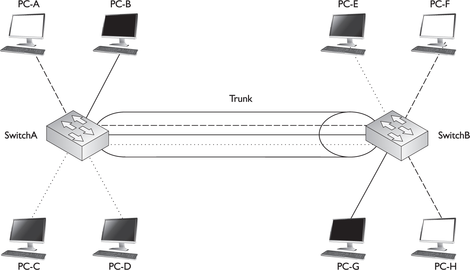
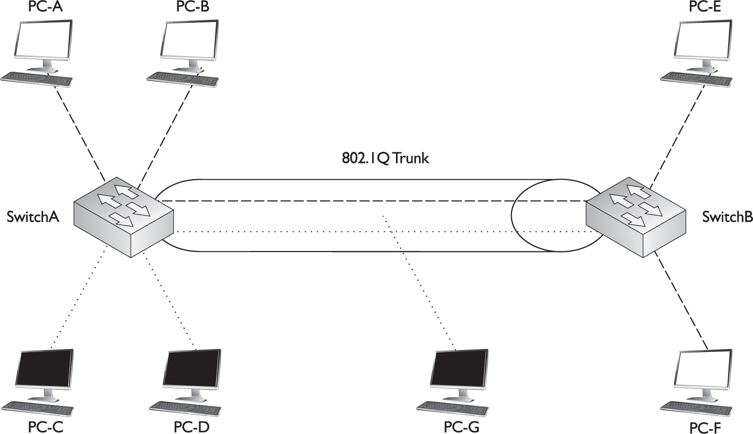
Figure 2-4 shows an example of a trunk connection between SwitchA and SwitchB in a network that has three VLANs. In this example, PC-A, PC-F, and PC-H belong to one VLAN; PC-B and PC-G belong to a second VLAN; and PC-C, PC-D, and PC-E belong to a third VLAN. The trunk between the two switches is also tagging VLAN information so that the remote switch understands the source VLAN of the originator.
FIGURE 2-4 Trunking example
Let’s take a look at an example of the use of VLANs and the two different types of connections by using the network shown in Figure 2-5. In this example, PC-C generates a local broadcast. When SwitchA receives the broadcast, it examines the incoming port and knows that the source device is from the gray VLAN (the access link connections are marked with dots). Seeing this, the switch knows to forward this frame only out of ports that belong to the same VLAN: this includes access link connections with the same VLAN identifier and trunk connections. On this switch, one access link connection belongs to the same VLAN, PC-D, so the switch forwards the frame directly out this interface.
FIGURE 2-5 Broadcast traffic example

The trunk connection between SwitchA and SwitchB handles traffic for multiple VLANs. A VLAN tagging mechanism is required to differentiate the source of traffic when moving it between the switches. For instance, assume that no tagging mechanism took place between the switches. PC-C generates a broadcast frame, and SwitchA forwards it unaltered to PC-D and then SwitchB across the trunk. The problem with this process is that when SwitchB receives the original Ethernet frame, it has no idea what port or ports to forward the broadcast to, since it doesn’t know the origin VLAN.
As shown in Figure 2-5, SwitchA tags the broadcast frame, adding the source VLAN to the original Ethernet frame (the broadcast frame is tagged). When SwitchB receives the frame, it examines the tag and knows that this is meant only for the VLAN to which PC-E belongs. Of course, since PC-E is connected via an access link connection, SwitchB first strips off the tagging and then forwards the original Ethernet frame to PC-E. This is necessary because PC-E has a standard NIC and doesn’t understand VLAN tagging. Through this process, both switches maintained the integrity of the broadcast domain.
802.1Q
ISL, which is Cisco proprietary, is being phased out in Cisco’s products and being replaced with IEEE’s 802.1Q trunking standard, which was introduced in 1998. One of the advantages provided by the IEEE standard is that it allows trunks between different vendors’ devices, whereas ISL is supported only on certain Cisco devices. Therefore, you should be able to implement a multivendor trunking solution without having to worry about whether or not a specific type of trunk connection is or is not supported. The 2960 switches, as well as Cisco’s higher-end switches such as the 6500 series, support 802.1Q. Actually, the 2960 series of switches support only 802.1Q trunking—they don’t support ISL. 802.1Q trunking is supported on switch ports that are capable of either Fast or Gigabit Ethernet speeds.
802.1Q trunks support two types of frames: tagged and untagged. An untagged frame does not carry any VLAN identification information in it—basically, this is a standard, unaltered Ethernet frame. The VLAN membership for the frame is determined by the switch’s port configuration: if the port is configured in VLAN 1, the untagged frame belongs to VLAN 1. This VLAN is commonly called a native VLAN. A tagged frame contains VLAN information, and only other 802.1Q-aware devices on the trunk will be able to process this frame.
One of the unique aspects of 802.1Q trunking is that you can have both tagged and untagged frames on a trunk connection, such as that shown in Figure 2-6. In this example, the white VLAN (PC-A, PC-B, PC-E, and PC-F) uses tagged frames on the trunk between SwitchA and SwitchB. Any other device that is connected on this trunk line would need to have 802.1Q trunking enabled to see the tag inside the frame to determine the source VLAN of the frame. In this network, a third device is connected to the trunk connection: PC-G. This example assumes that a hub connects the two switches and the PC together.
FIGURE 2-6 802.1Q trunk and native VLAN
PC-G has a normal Ethernet NIC and obviously wouldn’t understand the tagging and would drop these frames. However, this presents a problem: PC-G belongs to the dark VLAN, where PC-C and PC-D are also members. Therefore, in order for frames to be forwarded among these three members, the trunk must also support untagged frames so that PC-G can process them. To set this up, you would configure the switch-to-switch connection as an 802.1Q trunk but set the native VLAN as the dark one, so that frames from this VLAN would go untagged across it and allow PC-G to process them.
One restriction placed on an 802.1Q trunk configuration is that it must be the same on both sides. In other words, if the dark VLAN is the native VLAN on one switch, the switch at the other end must have the native VLAN set to the dark VLAN. Likewise, if the white VLAN is having its frames tagged on one switch, the other switch must also be tagging the white VLAN frames with 802.1Q information.
With the 802.1Q tagging method, the original Ethernet frame is modified. A 4-byte field, called a tag field, is inserted into the header of the original Ethernet frame, and the original frame’s FCS (checksum) is recomputed on the basis of this change. The first 2 bytes of the tag are the protocol identifier. For instance, an Ethernet type frame has a protocol identifier value of 0x8100, indicating that this is an Ethernet tagged frame. The next 3 bits are used to prioritize the frame, which is defined in the IEEE 802.1p standard. The fourth bit indicates if this is an encapsulated Token Ring frame (Cisco no longer sells Token Ring products), and the last 2 bits are used for the VLAN identifier (number).
Figure 2-7 shows the process that occurs when tagging an Ethernet frame by inserting the 802.1Q field into the Ethernet frame header. As you can see in this figure, step 1 is the normal, untagged Ethernet frame. Step 2 inserts the tag and recomputes a new FCS value. Below step 2 is a blow-up of the actual tag field. As you can see in this figure, the tag is inserted directly after the source and destination MAC addresses in the Ethernet header.
FIGURE 2-7 802.1Q framing process

802.1Q is a standardized trunking method that inserts a 4-byte field into the original Ethernet frame and recalculates the FCS. The 2950s and 2960s support only 802.1Q trunking. The native VLAN contains untagged frames, even on trunk connections. 802.1Q requires that interfaces be capable of Fast Ethernet speeds or higher; however, an 802.1Q- capable interface can be configured at 10 Mbps and still support trunking with 802.1Q. Both Cisco devices connected to the trunk must be configured for 802.1 with the same native VLAN; otherwise the trunk will fail.
One advantage of using this tagging mechanism is that, since you are adding only 4 bytes, your frame size will not exceed 1518 bytes, and thus you could actually forward 802.1Q frames through the access link connections of switches, since these switches would forward the frame as a normal Ethernet frame.
CERTIFICATION OBJECTIVE 2.03
VLAN Trunk Protocol
The VLAN Trunk Protocol (VTP) is a proprietary Cisco protocol used to share VLAN configuration information between Cisco switches on trunk connections. VTP allows switches to share and synchronize their VLAN information, which ensures that your network has a consistent VLAN configuration.
Assume, for instance, that you have a network with two switches and you need to add a new VLAN. This could easily be accomplished by adding the VLAN manually on both switches. However, this process becomes more difficult and tedious if you have 30 switches. In this situation, you might make a mistake in configuring the new VLAN on one of the switches, giving it the wrong VLAN identifier, or you might forget to add the new VLAN to one of the 30 switches. VTP can take care of this issue. With VTP, you can add the VLAN on one switch and have this switch propagate the new VLAN, via VTP messages, to all of the other switches in your layer 2 network, causing them to add the new VLAN also.
This is also true if you modify a VLAN’s configuration or delete a VLAN—VTP can verify that your VLAN configuration is consistent across all of your switches. VTP can even perform consistency checks with your VLANs to make sure that all the VLANs are configured identically. For instance, some of these components of a VLAN include the VLAN number, name, and type. If you have a VLAN number of 1 and a name of “admin” on one switch, but a name of “administrator” on a second switch for this VLAN, VTP can check for and fix these kinds of configuration mismatches.
VTP messages will propagate only across trunk connections, so you will need to set up trunking between your switches in order to share VLAN information via VTP. VTP messages are propagated as layer 2 multicast frames. Therefore, if a router separates two of your switches, the router will not forward the VTP messages from one of its interfaces to another.
In order for VTP to function correctly, you must associate your switch with a VTP domain. A domain is a group of switches that have the same VLAN information applied to them. Basically, a VTP domain is similar to an autonomous system, which some routing protocols use (autonomous systems and routing protocols are introduced in Chapter 4). A switch can belong only to a single domain. Domains are given names, and when switches generate VTP messages, they include the domain name in their messages. An incoming switch will not incorporate the VLAN changes in the received VTP message if the domain name in the message doesn’t match the domain name configured on itself. In other words, a switch in one domain will ignore VTP messages from switches in other domains. The following sections cover the components and messages that VTP uses, as well as some of the advantages that it provides, such as pruning.
VTP is a Cisco-proprietary protocol that traverses trunks. It is used to create a consistent VLAN configuration across all switches in the same domain: A VLAN can be added on one switch and propagated to other switches; however, switches will ignore VTP messages from other VTP domains.
VTP Modes
When you are setting up VTP, you can choose from three different modes for your switch’s configuration:
![]() Client
Client
![]() Server
Server
![]() Transparent
Transparent
Table 2-2 shows the differences between these VTP modes.
TABLE 2-2 Description of VTP Modes

A switch configured in either VTP server or transparent mode can add, modify, and delete VLANs. The main difference between these modes is that the configuration changes made to a transparent switch affect only that switch and no other switch in the network. A VTP server switch, however, will make the change and then propagate a VTP message concerning the change on all of its trunk ports. If a server switch receives a VTP message, it will incorporate the update and forward the message out its remaining trunk ports. A transparent switch, on the other hand, ignores VTP messages—it will accept them on trunk ports and forward them out its remaining trunk ports, but it will not incorporate the changes in the VTP message in its local VLAN configuration. In this sense, transparent switches are like little islands, where changes on a transparent switch affect no one else but the transparent switch itself, and changes on other switches do not affect transparent switches.
Remember the differences among the VTP modes in Table 2-2.
A VTP client switch cannot make changes to its VLAN configuration itself—it requires a server switch to tell it about the VLAN changes. When a client switch receives a VTP message from a server switch, it incorporates the changes and then floods the VTP message out its remaining trunk ports.
Normally, you would set up one switch in server mode and all other switches in client mode. Then you would control who could make changes on the server switch. However, you should keep in mind that if you make a VLAN configuration mistake on the server switch, this mistake is automatically propagated to all the client switches in your network. Imagine that you accidentally deleted a VLAN on your server switch, and this VLAN had 500 devices in it. When this occurs, all the switches remove the VLAN from their configuration.
Given this problem, some administrators don’t like to use VTP server and client modes; they prefer to configure all of their switches in transparent mode. The problem with transparent mode is that it isn’t very scalable; if you need to add a VLAN to your network and your network has 20 switches, you would have to add the VLAN manually to each individual switch, which is a time-consuming process. Of course, the advantage of this approach is that if you make a mistake on a transparent switch, the problem is not propagated to other switches: it’s localized.
You could also set up all of your switches in server mode, which is the default setting for VTP. As you can see, a wide range of VTP configuration options is available. You could even mix and match these options. Set up a couple of server switches, and have the remaining switches as clients, or set your switches initially as servers and clients, add all your VLANs on the server switch, allow the clients to acquire this information, and then change all the switches to transparent mode. This process allows you to populate your switches’ configurations easily with a consistent VLAN configuration during the setup process. Note that if you don’t specify the VTP mode for your switch, it will default to server.
VTP Messages
If you use a client/server configuration for VTP, these switches can generate three types of VTP messages:
![]() Advertisement request
Advertisement request
![]() Subset advertisement
Subset advertisement
![]() Summary advertisement
Summary advertisement
An advertisement request message is a VTP message a client generates to acquire VLAN information, to which a server will respond. When the server responds to a client’s request, it generates a subset advertisement. A subset advertisement contains detailed VLAN configuration information, including the VLAN numbers, names, types, and other information. The client will then configure itself appropriately.
A summary advertisement is also generated by a switch in VTP server mode. Summary advertisements are generated every 5 minutes (300 seconds) by default, or when a configuration change takes place on the server switch. Unlike a subset advertisement, a summary advertisement contains only summarized VLAN information.
When a server switch generates a VTP advertisement, it can include the following information:
![]() The number and name of the VLAN
The number and name of the VLAN
![]() The MTU size used by the VLAN
The MTU size used by the VLAN
![]() The frame format used by the VLAN
The frame format used by the VLAN
![]() The Security Association ID (SAID) value for the VLAN (needed if it is an 802.10 VLAN, which is implemented in networks using FDDI)
The Security Association ID (SAID) value for the VLAN (needed if it is an 802.10 VLAN, which is implemented in networks using FDDI)
![]() The configuration revision number
The configuration revision number
![]() The name of the VTP domain
The name of the VTP domain
This list includes a couple of important items that should be discussed further. Switches in either server or client mode will process VTP messages if they are in the same VTP domain; however, some restrictions are placed on whether the switch should incorporate the changes or not. For instance, one function of the VTP summary advertisements is to ensure that all of the switches have the most current changes. If you didn’t make a change on a server switch in the 5-minute update interval, when the countdown timer expires, the server switch still sends out a summary advertisement with the same exact summary information. It makes no sense to have other switches, which have the most up-to-date information, incorporate the same information in their configuration.
To make this process more efficient, the configuration revision number is used to keep track of what server switch has the most recent changes. Initially, this number is set to zero (0). If you make a change on a server switch, it increments its revision number and advertises this to the other switches across its trunk links. When a client or server switch receives this information, it compares the revision number in the message to the last message it received. If the newly arrived message has a higher number, this server switch must have made changes. If the necessary VLAN information isn’t in the VTP summary advertisement, all client and server switches will generate an advertisement request, and the server will respond with the details in a subset advertisement.
VTP servers generate VTP multicasts every 5 minutes. The configuration revision number is used to determine which server has the most up-to-date VLAN information: the highest number is the most current. Remember that when connecting an existing server switch to an existing server/client VTP network, whichever server switch has the highest revision number will win out and its VLANs will be used: the VLANs from the other switch(es) will be deleted.
If a server switch receives a VTP message from another server, and the advertising server has a lower revision number, the receiving server switch will respond to the advertising server with a VTP message with its current configuration revision number. This will tell the advertising server switch that it doesn’t have the most up-to-date VLAN information and should request it from the server that does. In this sense, the revision number used in a VTP message is somewhat similar to the sequence number used in TCP. Also, remember that transparent switches are not processing these VTP advertisements—they simply passively forward these messages to other switches on their trunk ports.
IOS switches save the VLAN database and revision value in the vlan.dat file, not the startup-config file: server, transparent, and client mode switches. The erase startup-config command will not delete this file. Therefore, it is possible that if you boot up a switch that has a higher revision number than an existing server switch in a domain, the switch’s VLAN configuration could overwrite the existing VLAN information in the domain. You should delete the vlan.dat file on the switch before adding it to an existing network. This is done from Privileged EXEC mode with this command: delete vlan.dat. You must press ENTER twice after executing the command to confirm your option.
VTP Pruning
VTP pruning is a Cisco feature that allows your switches dynamically to delete or add VLANs to a trunk, creating a more efficient switching network. By default, all VLANs are associated with a trunk connection. This means that if a device in any VLAN generates a broadcast, multicast, or an unknown unicast, the switch will flood this frame out all ports associated with the source VLAN port, including trunks. In many situations, this flooding is necessary, especially if the VLAN spans multiple switches. However, it doesn’t make sense to flood a frame to a neighboring switch if that switch doesn’t have any active ports in the source VLAN.
Trunking Without Pruning
Let’s take a look at a simple example by examining Figure 2-8. In this example, VTP pruning is not enabled. PC-A, PC-B, PC-E, and PC-F are in the same VLAN. If PC-A generates a broadcast, SwitchA will forward this to the access link to which PC-B is connected as well as the trunk (since a trunk is a member of all VLANs, by default). This makes sense, since PC-E and PC-F, connected to SwitchB, are in the same VLAN.
FIGURE 2-8 Without VTP pruning
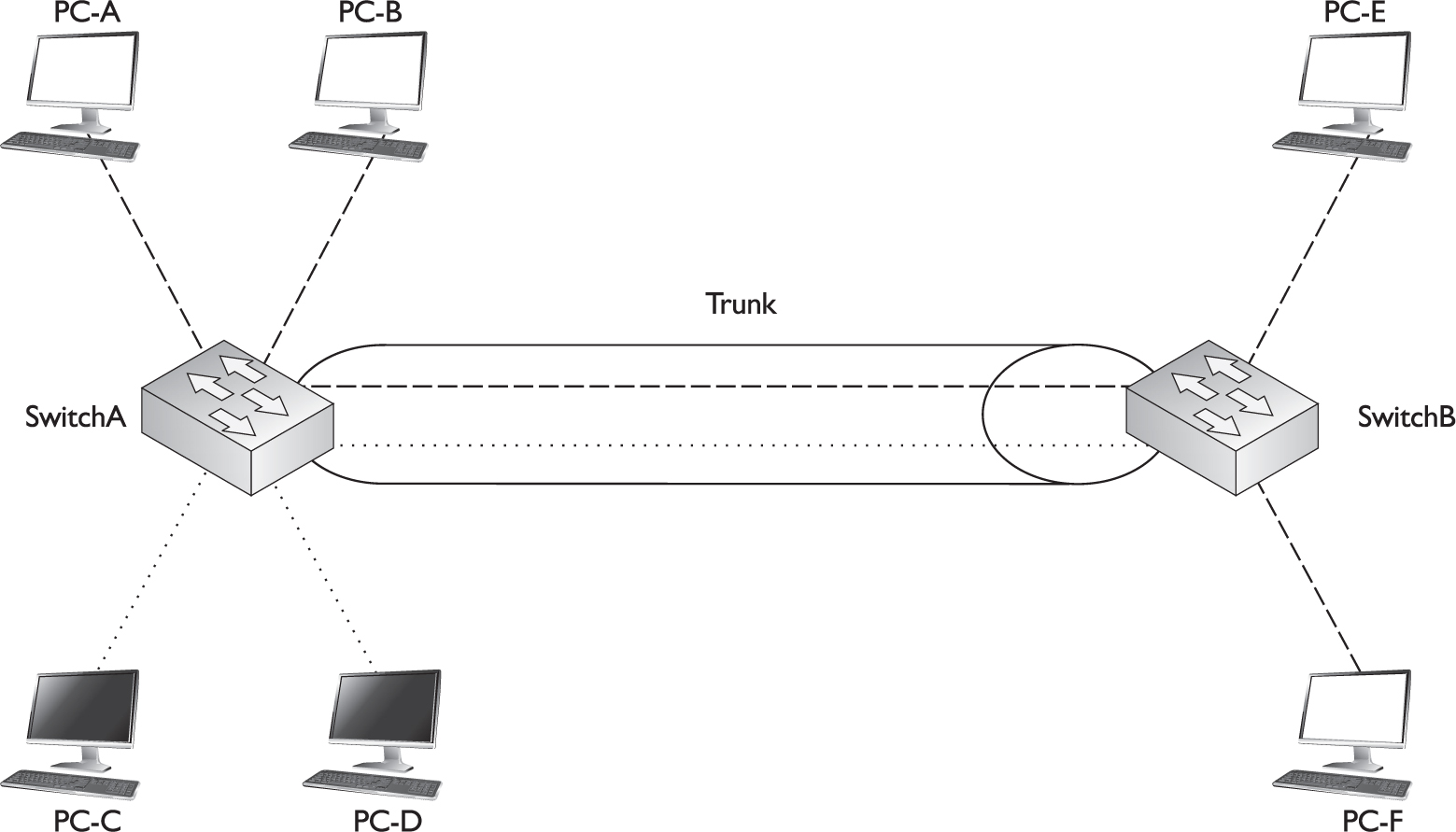
Figure 2-8 shows a second VLAN with two members: PC-C and PC-D. If PC-C generates a local broadcast, SwitchA will obviously send to this to PC-D’s port. What doesn’t make sense is that SwitchA will flood this broadcast out its trunk port to SwitchB, considering that no devices on SwitchB are in this VLAN. This is an example of wasting bandwidth and resources. A single broadcast isn’t a big problem; however, imagine this were a video multicast stream at 5 Mbps coming from PC-A. This network might experience throughput problems on the trunk, since a switch treats a multicast just like a broadcast—it floods it out all ports associated with the source port’s VLAN.
You could use one of two methods to fix this problem: static VLAN pruning or dynamic VLAN pruning. With a static configuration, you would manually prune the inactive VLAN off the trunk on both switches, as shown in Figure 2-9. Notice that in this figure, the dark VLAN (indicated by dotted lines) has been pruned from the trunk. The problem with manual pruning is that if you add a dark VLAN member to SwitchB, you will have to log into both switches and manually add the pruned VLAN back to the trunk. This can become very confusing in a multiswitched network with multiple VLANs, where every VLAN is not necessarily active on every switch. It would be easy to accidentally prune a VLAN from a trunk that shouldn’t have been pruned, thus creating connectivity problems.
FIGURE 2-9 VLAN pruning

Trunking with Pruning
The VTP pruning feature allows the switches to share additional VLAN information and allows them to prune inactive VLANs dynamically from trunk connections. In this instance, the switches share which VLANs are active. For example, SwitchA tells SwitchB that it has two active VLANs (the white one and the dark one). SwitchB, on the other hand, has only one active VLAN, and it shares this fact with SwitchA. Given the shared information, both SwitchA and SwitchB realize that the dark VLAN is inactive across their trunk connection and therefore the dark VLAN should be dynamically removed from the trunk’s configuration.
By default, all VLANs can traverse a trunk. VTP pruning is used on trunk connections to dynamically remove VLANs not active between the two switches. It must be enabled on a VTP server switch, and the other switches must be either servers or clients.
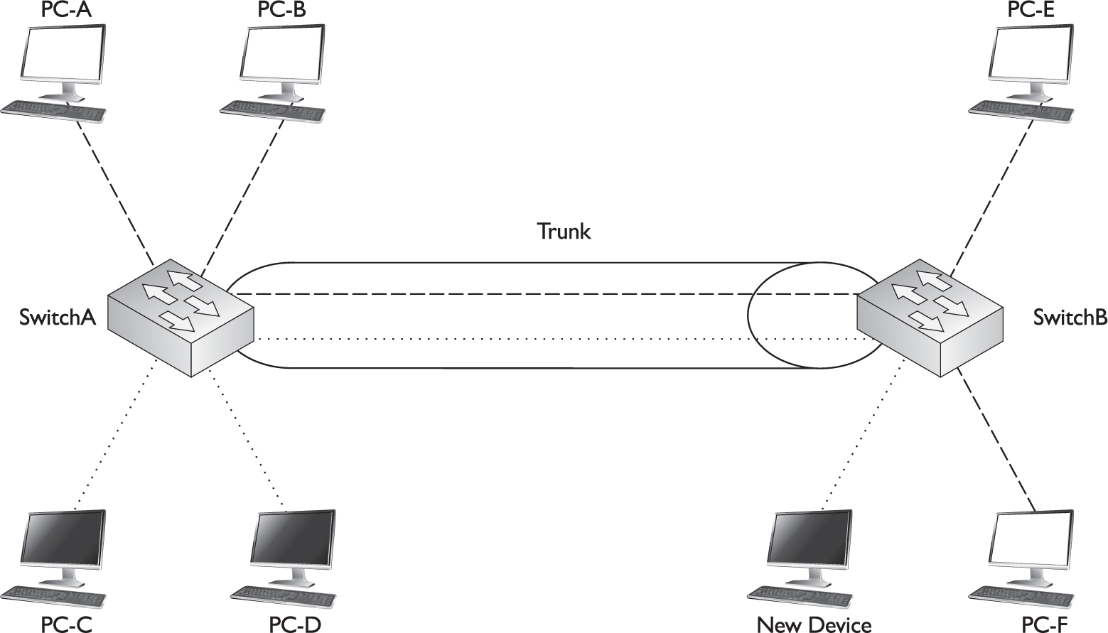
The nice thing about this feature is that if you happen to activate the dark VLAN on SwitchB by connecting a device to a port on the switch and assigning that port to the dark VLAN, SwitchB will notify SwitchA about the newly active VLAN, and both switches will dynamically add the VLAN back to the trunk’s configuration. This will allow PC-C, PC-D, and the new device to send frames to each other, as is shown in Figure 2-10.
FIGURE 2-10 VTP pruning activating a VLAN on a trunk
Only a VTP switch in server mode can enable VTP pruning, and the remaining switches in the domain must be either in VTP server or client mode. If you have transparent mode switches, you’ll have to prune VLANs off their trunk links manually.
VLAN Configuration
Unlike Cisco routers, every Cisco switch comes with a default configuration. For instance, some preconfigured VLANs are already on the switch, including VLAN 1. During the configuration, all VLAN commands refer to the VLAN number, even though you can configure an optional name for the VLAN. Every port on your switch, by default, is associated with VLAN 1. And all communications from the switch itself—VTP messages, Cisco Discovery Protocol (CDP) multicasts (discussed in Chapter 7), and other traffic the switch originates—occur in VLAN 1. Recall from your CCENT studies that the 2960’s IP configuration is based on the VLAN interface for which you configure your IP address.
VLAN 1 is sometimes called the management VLAN, even though you can use a different VLAN. It is a common practice to put all of your management devices—switches, manageable hubs, and management stations—in their own VLAN. If you decide to put your switch in a different VLAN than VLAN 1, it is recommended that you change this configuration on all your management devices so that you can more easily secure them, since other VLANs would have to go through a layer 3 device to access them; and on this layer 3 device, you can set up access control lists to filter unwanted traffic.
It’s important that all your switches are in the same VLAN, since many of the switches’ management protocols, such as CDP, VTP, and the Dynamic Trunk Protocol (DTP), which is discussed later in this chapter, occur within the switch’s management VLAN. If one switch had its management VLAN set to 1 and another connected switch had it set to 2, the two switches would lose a lot of inter-functionality.
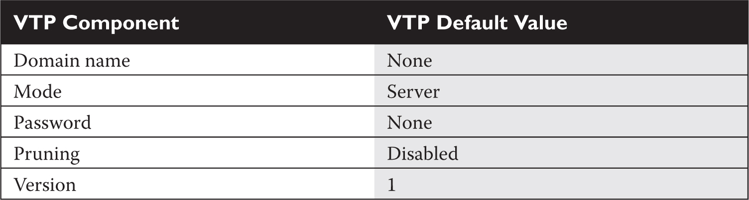
Remember the VTP defaults listed in Table 2-3.
Configuring VTP
One of the very first VLAN configuration tasks you’ll perform on your switch is to set up VTP. Table 2-3 shows the default VTP configuration of the 2960 switches. The following sections cover the configuration of VTP on the two switches.
TABLE 2-3 VTP Default Configuration Values
Your VTP configuration is done from Global Configuration mode on the 2960:
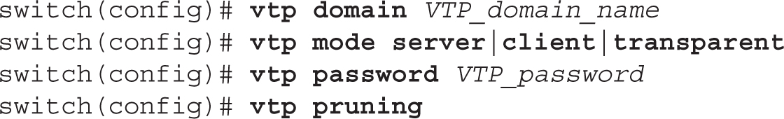
The vtp domain command defines the domain name for your switch. Remember that in order for switches to share VTP information, they must be in the same domain. Messages received from other domains are ignored. If you don’t configure a domain name, the switch will learn this from a server advertisement.
The rest of the commands in the configuration are optional. The second vtp command defines the VTP mode of the switch. If you don’t configure this command, the default mode is server. You can configure a VTP MD5 password for your switches, which must match the password configured on every switch in the domain. Switches will use this password to verify VTP messages from other switches; if the created hashed values placed in VTP messages (generated by taking the VTP message and password and running it through MD5 to create the hash signature) can’t be verified, the switches ignore the VTP messages. On the 2960 switches, pruning is disabled by default, but you can disable or enable it with the vtp pruning command. It is important to note that if pruning is enabled on a server switch, the server switch will propagate this to all other server and client switches in the same domain.
Once you are done configuring VTP, use this command to check your configuration:

In this example, 17 configuration changes have occurred (examine the Configuration Revision field). The switch is operating in server mode in the dealgroup domain.
The vtp password command is used to authenticate VTP messages between switches. The show vtp status command will display the VTP mode in which the switch is operating, the configuration revision number, and the VTP domain to which the switch belongs.
The following command displays VTP statistics concerning VTP messages sent and received:

In this example, you can see that the switch has sent and received VTP summary advertisements.

2.01. The digital resources that accompany this book contain a multimedia demonstration of configuring and verifying VTP on a switch.
Configuring Trunks
This section covers the setup of trunk connections on your switches using the 802.1Q trunking protocol. Before getting into the configuration, however, you should first be familiar with a protocol that is used to form a trunk between two devices: the Dynamic Trunk Protocol (DTP). One limitation of trunks is that they don’t work with the port security and 802.1x authentication features; these features are used on access links.
Dynamic Trunk Protocol (DTP)
Cisco’s proprietary trunking protocol is used on trunk connections to form trunks dynamically. DTP is used to form and verify a trunk connection dynamically between two Cisco switches. DTP supports five trunking modes, shown in Table 2-4.
TABLE 2-4 DTP Modes and Operation

If the trunk mode is set to on or trunk for an interface, this causes the interface to generate DTP messages on the interface and to tag frames on the interface, based on the trunk type (802.1Q on the 2960s). When set to on, the trunk interface always assumes the connection is a trunk, even if the remote end does not support trunking. Some of Cisco’s switches use the term trunk instead of on, such as the 2960s.
If the trunk mode is set to desirable, the interface will generate DTP messages on the interface, but it will make the assumption that the other side is not trunk capable and will wait for a DTP reply message from the remote side. In this state, the interface starts as an access link connection. If the remote side sends a DTP message, and this message indicates that trunking is compatible between the two switches, a trunk will be formed and the switch will start tagging frames on the interface. If the other side does not support trunking, the interface will remain as an access link connection.
If the trunk mode is set to auto, the interface passively listens for DTP messages from the remote side and leaves the interface as an access link connection. If the interface receives a DTP message, and the message matches trunking capabilities of the interface, then the interface will change from an access link connection to a trunk connection and start tagging frames. This is the default DTP mode for a Cisco switch interface that is trunk capable.
If an interface is set to no-negotiate, the interface is set as a trunk connection and will automatically tag frames with VLAN information; however, the interface will not generate DTP messages: DTP is disabled. This mode is typically used when connecting trunk connections to non-Cisco devices that don’t understand Cisco’s proprietary trunking protocol and thus won’t understand the contents of these messages.
If an interface is set to off, the interface is configured as an access link. No DTP messages are generated in this mode, nor are frames tagged.
Table 2-5 shows when switch connections will form a trunk. In this table, one side needs to be configured as either on or desirable and the other side as on, desirable, or auto, or both switches need to be configured as no-negotiate. Note that if you use the no-negotiate mode, trunking is formed but DTP is not used, whereas if you use on, desirable, or auto, DTP is used. One advantage that DTP has over nonegotiate is that DTP checks for the trunk’s characteristics: if they don’t match on the two sides (for instance, as to the type of trunk or a mismatch with the native VLAN), then the trunk will not come up and the interfaces will remain as an access link connection. With no-negotiate, if the trunking characteristics don’t match on the two sides, the trunk connection will probably fail.
TABLE 2-5 Forming Trunks

Remember the DTP information in Tables 2-4 and 2-5 for the exam. The result of a successful DTP completion is the formation of an 802.1Q trunk. When using DTP autosensing, if the native VLAN doesn’t match, a native VLAN mismatch error will occur.
Switch Trunk Configuration
Setting up a trunk on a 2960 is the same as on most of Cisco’s IOS switches:
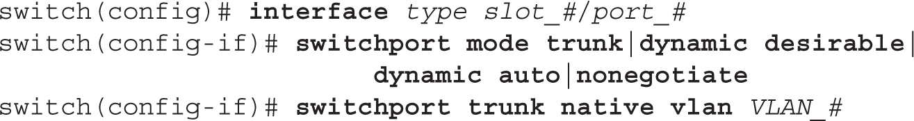
All ports on a 2960 switch support trunking. Remember that the 2960 supports only 802.1Q trunking, so you must set up a trunk connection only to other 802.1Q trunking devices. If you want a trunk to be in an on state, use the trunk parameter. For a desirable DTP state, use dynamic desirable, and for an auto state, use dynamic auto. The default mode is auto. If you don’t want to use DTP but still want to perform trunking, use the nonegotiate parameter. For 802.1Q trunks, the native VLAN is VLAN 1. You can change this with the switchport trunk native vlan command, but then you’ll need to match up the native VLAN on all switches in the layer 2 network. If two interconnected switches have a different native VLAN on the connecting trunks, then traffic from one VLAN on one switch will end up in a different VLAN on the remote switch, which can create all kinds of problems.
Use the switchport mode command to enable trunking on a switch. Use the switchport trunk native vlan command to designate the untagged traffic. By default, this is VLAN 1. Mismatched native VLANs between switches can create connectivity problems.
After you have configured your trunk connection, you can use this command to verify it:
![]()
Here’s an example using the switchport parameter:

In this example, FA0/1’s trunking mode is set to trunk (on), with the native VLAN set to 1. Here’s an example using the trunk parameter:
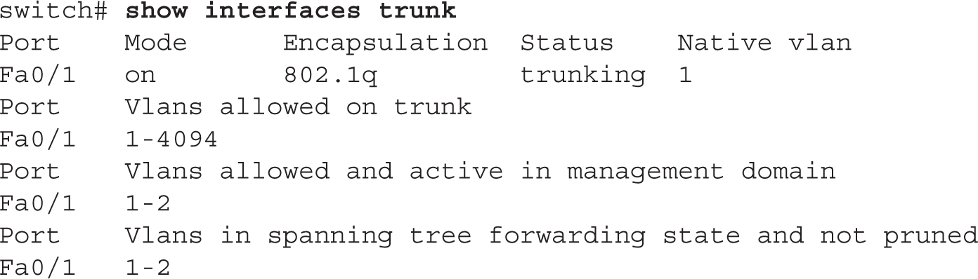
Use the show interfaces switchport|trunk command to verify trunking. Be familiar with the output of this command.
In this example, one interface is trunking—fa0/1: the trunking mode is on, the trunking protocol is 802.1Q, and the native VLAN is 1.
When executing the show mac address-table command, if you see multiple MAC addresses associated with a single interface, this can indicate that the interface is a trunk connection or that the interface is an access link connection to another switch or hub. Switches typically have a separate MAC address table for each VLAN to simplify the lookup process for a MAC address on trunk connections.
2.02. The digital resources that accompany this book contain a multimedia demonstration of configuring trunking on a switch.

Configuring Trunks on Your Switches
The last few sections dealt with setting up trunks on Cisco switches. You’ll perform this lab using Boson’s NetSim simulator. This exercise has you set up a trunk link between the two 2950 switches (2950-1 and 2950-2). You can find a picture of the network diagram for the NetSim simulator in the Introduction of this book. After starting up the simulator, click the Labs tab at the bottom left of the window. Click the McGraw-Hill Education tab (to the right of the Standard and Custom tabs) at the top left, and then double-click Exercise 2-1. This will load the lab configuration based on a simple configuration.
1. On the 2950-1 switch, set the trunk mode to trunk for the connection between the two 2950 switches and examine the status. Does the trunk come up?
Under the Lab Instructions tab, use the drop-down selector for Devices to choose 2950-1; or click the NetMap tab and double-click the 2950-1 device icon. Access Configuration mode: enable and configure terminal. Go into the interface: interface fa0/1. Set the trunk mode to trunk: switchport mode trunk. Exit Configuration mode: end. Use the show interfaces trunk command to verify the status. You might have to wait a few seconds, but the trunk should come up. If one side is set to on or desirable and the other is set to on, desirable, or auto (default), then the trunk should come up.
2. Save the configuration on the switch: copy running-config startup-config.
3. On the 2950-2 switch, set the trunk mode to trunk for the connection between the two 2950 switches and verify the trunking status of the interface.
Under the Lab Instructions tab, use the drop-down selector for Devices to choose 2950-2; or click the NetMap tab and double-click the 2950-2 device icon. Access Configuration mode: enable and configure terminal. Go into the interface: interface fa0/1. Set the trunk mode to trunk: switchport mode trunk. Exit Configuration mode: end. Use the show interfaces trunk command to verify the status.
4. Save the configuration on the switch: copy running-config startup-config.
Now you should be more comfortable with setting up trunks on your switches. In the next section, you will be presented with setting up VLANs and associating interfaces to your VLANs.
Creating VLANs
This section covers how you can create VLANs on your switches and then statically assign access link connections (interfaces) to your newly created VLANs. Here are some guidelines to remember when creating VLANs:
![]() The number of VLANs you can create is dependent on the switch model and IOS software.
The number of VLANs you can create is dependent on the switch model and IOS software.
![]() Some VLANs are preconfigured on every switch, including VLAN 1 and 1002–1005 (1002–1005 are used in Token Ring and FDDI networks only). These VLANs cannot be deleted!
Some VLANs are preconfigured on every switch, including VLAN 1 and 1002–1005 (1002–1005 are used in Token Ring and FDDI networks only). These VLANs cannot be deleted!
![]() To add or delete VLANs, your switch must use either VTP server or transparent mode.
To add or delete VLANs, your switch must use either VTP server or transparent mode.
![]() VLAN names can be changed; VLAN numbers can’t: you must delete a VLAN and re-add it in order to renumber it.
VLAN names can be changed; VLAN numbers can’t: you must delete a VLAN and re-add it in order to renumber it.
![]() All interfaces, by default, belong to VLAN 1.
All interfaces, by default, belong to VLAN 1.
![]() CDP, DTP, and VTP advertisements are sent in the native VLAN, which is VLAN 1, by default.
CDP, DTP, and VTP advertisements are sent in the native VLAN, which is VLAN 1, by default.
![]() Before deleting VLANs, reassign any ports from the current VLAN to another; if you don’t, any ports from the deleted VLAN will be inoperable.
Before deleting VLANs, reassign any ports from the current VLAN to another; if you don’t, any ports from the deleted VLAN will be inoperable.
![]() Unknown destination MAC addresses are only flooded in the VLAN in which the source MAC address resides.
Unknown destination MAC addresses are only flooded in the VLAN in which the source MAC address resides.
Remember the bulleted items for the exam.
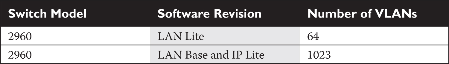
Table 2-6 lists the VLAN capabilities of the 2960-X switches.
TABLE 2-6 VLAN Capabilities of the 2960 Cisco Switches
You can use two methods—an old one and a new one—to create VLANs on your 2960 switch. The old method requires you to go into the VLAN database in Privileged EXEC mode and create the VLAN (this is not covered in this book or the exam). The new method creates the VLAN from Configuration mode, like this:

When you execute the vlan command, you are taken into VLAN Subconfiguration mode, where you can enter your configuration parameters for the VLAN, such as its name. Use the no parameter in front of the vlan command to delete it.
Cisco recommends you use the newer method to create VLANs on your switches: the Global Configuration vlan command. Remember that your switch must be a VTP server or transparent switch to create or delete VLANs on it. Also, before you delete a VLAN, move all ports in the VLAN to a different one; otherwise, ports associated with a deleted VLAN will not be able to communicate with other ports until you either re-add the VLAN number back or move the ports to an existing VLAN. When this happens, the port LED(s) will be solid amber.
Once you have created your VLANs, you need to assign your VLANs to your switch’s interfaces using the following configuration:

The first thing you must do is specify that the connection is an access link connection with the switchport mode access command. The switchport access vlan command assigns a VLAN to the access link connection.
If you associate a nonexistent VLAN to a switch port with the switchport access vlan command, IOS will automatically create the VLAN.
Once you have created and assigned your VLANs, you can use various show commands to review and verify your configuration. The show vlan command displays the list of VLANs and which ports are assigned to them:

In this example, all the ports are assigned to VLAN 1. You can add the brief parameter to this command and it will not display the details for each VLAN at the bottom of the display. You can also use the show interface switchport command to see a specific interface’s VLAN membership information. This command was shown earlier in the chapter in the “Switch Trunk Configuration” section.
2.03. The digital resources that accompany this book contain a multimedia demonstration of configuring VLANs on a switch.
Use the vlan database or vlan command to create a VLAN. Use the switchport mode access and switchport access vlan commands to assign a VLAN to an interface. If an interface is configured as an access link, it cannot form a trunk. The show vlan command displays VLAN information: if the same interface is displayed for multiple VLANs, this interface is probably a trunk.
Basic Troubleshooting of VLANs and Trunks
Now that you know how to set up a VLAN-based network, you will eventually run into a problem that is related to your VLAN configuration. You should check the following, in order, to determine the cause of the problem:
1. Check the status of your interface to determine whether it is a physical layer problem.
2. Check your switches’ and routers’ configuration to make sure nothing was added or changed.
3. Verify that your trunks are operational.
4. Verify that your VLANs are configured correctly and that the Spanning Tree Protocol (STP), discussed in Chapter 3, is functioning correctly.
The following sections cover some of the basic things that you should check whenever you experience switching problems.
Performance Problems
If you are experiencing slow performance or intermittent connection problems, you should first check the statistics on the interfaces of your switch with the show interfaces command. Are you seeing a high number of errors, such as collisions?
A few things can cause these problems. The most common is a mismatch in either the duplexing or the speed on a connection. Examine the settings on both sides of the connection. Also, make sure that you are using the correct cabling type: straight for a DTE-to-DCE connection and crossover for a DTE-to-DTE or DCE-to-DCE connection (as covered in your CCENT studies). And make sure that the cable does not exceed the maximum legal limit. Also, make sure that the connected IC is not experiencing a hardware problem or failure.
Local Connection Problems
If you are attempting to access the console port of a switch or router, and all you see is garbage in your terminal session, this could indicate an incorrect terminal setting. Usually the culprit is an incorrect baud rate. Some devices allow you to perform an operating system upgrade via the console port, and an administrator might change it to the highest possible value but forget to change it back to 9600 bps. If you suspect this, keep on changing your baud rate until you find the right speed.
If you are having problems accessing devices in the switched network, you can look at a few options. First, is the device you are trying to reach in the same VLAN? If so, make sure that you are using the correct IP addressing scheme in the VLAN and that the two devices trying to share information have their ports in the same VLAN. If the two devices are Cisco devices, you can use CDP to elicit some of this information, for instance, the IP address, by using the show cdp commands (discussed in Chapter 7). Is the switch learning about the devices in your network? You might want to examine your CAM tables and make sure that a port security violation is not causing your connectivity problem (see Chapter 1).
For VLAN information, use the show commands on your switches to check your VLAN configuration. Also, check the VLAN configuration on each switch and make sure the VLANs are configured with the same parameters by using the show vlan command. If the port LED is solid amber, your problem could be that the port’s VLAN was deleted and the port wasn’t reassigned. Other problems can also cause the port LED to turn amber, such as STP placing the port in a blocking state (Chapter 3) or port security has disabled the port because of a security violation (Chapter 1). Actually, if you see that a lot of port LEDs are amber, a deleted VLAN is likely the problem. Use the show interface switchport command to determine whether a deleted VLAN is the problem: if you see that the VLAN assigned to the port is inactive, like this, then you’ve identified the culprit:
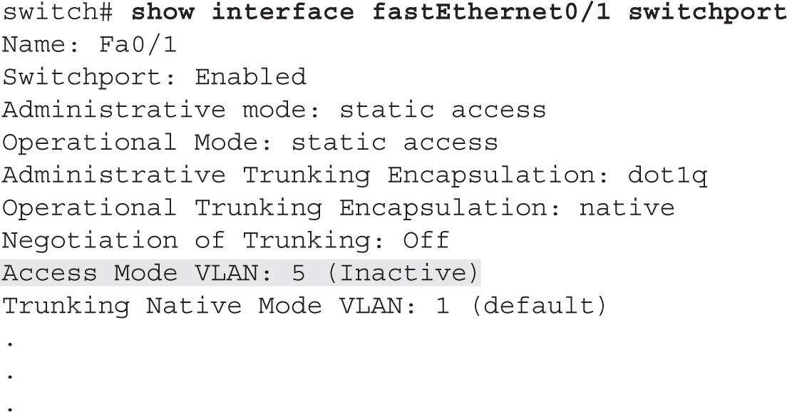
Notice that in this example VLAN 5 is inactive, indicating that the interface is assigned to the VLAN, but the VLAN was deleted, making the interface inoperable.
If you are using trunks between the switches, make sure that the trunks are configured correctly: show interface trunk. Make sure that the native VLAN number matches on both ends of the trunk: if they are mismatched, a trunk will not form.
Also, check VTP (if you are using it) by executing the show vtp commands. Make sure you have trunk connections between your switches, since VTP messages only traverse trunks. When using a server/client implementation, make sure that the domain name and, if using the password option, the password match among the VTP switches. Also, all switches must be running the same VTP version (by default, this is version 1).
Inter-VLAN Connection Problems
If you are having problems reaching devices in other VLANs, make sure that, first, you can ping the default gateway (router) that is your exit point from the VLAN. A common misconfiguration on a user’s PC is a misconfigured default gateway. If you can’t ping the default gateway, then go back to the preceding section and check local VLAN connectivity issues. If you can ping the gateway, check the router’s configuration and its interface (Chapter 6). Also, make sure that the router has a route to the destination VLAN (show ip route). This is covered in Chapters 9, 10, and 11. If you do have a route to the destination, make sure the destination VLAN is configured correctly and that the default gateway in that VLAN can reach the destination device.
Configuring VLANs on Your Switches
The last few sections dealt with the creation of VLANs and the assignment of interfaces to them. This lab builds upon this information and allows you to perform some of these configurations. You can find a picture of the network diagram for the simulator in the Introduction of this book. After starting up Boson’s NetSim simulator, click the Lab Instructions tab. Next, double-click Exercise 2-2. This will load the lab configuration based on Exercise 2-1.
1. From the 2950-1, verify that you can ping Host-1 connected to fa0/3. Also ping Host-2 connected to 2950-1’s fa0/4 interface.
2. Under the Lab Instructions tab, use the drop-down selector for Devices to choose 2950-1; or click the NetMap tab and double-click the 2950-1 device icon.
Access the CLI of the 2950-1. Execute ping 192.168.1.10 and ping 192.168.1.11. Both should be successful.
3. On the 2950-1, create VLAN 2. Then assign fa0/3 to VLAN 2 as an access link port. Examine your VLANs.
Access Configuration mode: enable and configure terminal. Use the vlan 2 command to create your VLAN. Go into the interface: interface fastethernet0/3. Assign the VLAN: switchport mode access and switchport access vlan 2. Exit out of Configuration mode: exit and exit.
4. View your VLANs on the 2950-1: show vlan. Make sure that all interfaces are in VLAN 1 except for fa0/3, which should be in VLAN 2.
5. From Host-1, ping Host-2 (192.168.1.11) connected to the 2950-1 switch. Is the ping successful?
Under the Lab Instructions tab, use the drop-down selector for Devices to choose Host-1; or click the NetMap tab and double-click the Host-1 device icon. Execute ping 192.168.1.11. The ping should fail, since Host-2 is in VLAN 1, while Host-1 is in VLAN 2.
6. On the 2950-1 switch, move Host-2 to VLAN 2 and verify your configuration.
Under the Lab Instructions tab, use the drop-down selector for Devices to choose 2950-1; or click the NetMap tab and double-click the 2950-1 device icon. On the 2950-1, go into the Host-2 interface: configure terminal and interface fa0/4. Assign the VLAN: switchport mode access, switchport access vlan 2, and exit. Exit out of Configuration mode: exit and exit.
7. View your VLANs: show vlan. Make sure that fa0/3 and fa0/4 are in VLAN 2.
8. From Host-1, ping Host-2 (192.168.1.11), which is connected to the 2950-1 switch. Is the ping successful? Can Host-1 ping the 2950-1 or 2950-2 switches?
Under the Lab Instructions tab, use the drop-down selector for Devices to choose Host-1; or click the NetMap tab and double-click the Host-1 device icon. Execute ping 192.168.1.11. The ping should be successful, since all connections from Host-1 to Host-2 are in VLAN 2. Execute ping 192.168.1.2 and ping 192.168.1.3. Both should fail, since both switches’ IP addresses are in VLAN 1 and the hosts are in VLAN 2.
Now you should be more comfortable with configuring VLANs on your switches.
CERTIFICATION SUMMARY
A VLAN is a group of devices in the same broadcast domain (subnet). To move among VLANs, you need a router. Static VLAN assignment to devices is also called port-based VLANs. An access link is a connection to a device that processes normal frames. Trunk connections modify frames to carry VLAN information. Ethernet trunking methods include ISL and 802.1Q. The 802.1Q method inserts a 4-byte field and recomputes the FCS for Ethernet frames; the 2960 switches support only 802.1Q.
VTP is a Cisco-proprietary protocol that transmits VLAN information across trunk ports. Switches must be in the same domain to share messages. There are three modes for VTP: client, server, and transparent. Server and transparent switches can add, change, and delete VLANs, but server switches advertise these changes. Clients can accept updates only from server switches. There are three VTP messages: advertisement request, subset advertisement, and summary advertisement. Servers generate summary advertisements every 5 minutes on trunk connections. The configuration revision number is used to determine which server switch has the most current VLAN information. VTP pruning is used to prune off VLANs that are not active between two switches, but it requires switches to be in server and/or client mode.
On the 2960, use the vtp domain command and vtp server|client|transparent commands to configure VTP. The default mode is server. To configure a VTP password, use the vtp password command.
DTP is a Cisco-proprietary trunking protocol. There are five modes: on (or trunk), off, desirable, auto, and no-negotiate. The on and desirable modes actively generate DTP messages; auto is the default. Use no-negotiate for non-Cisco switch connections. On the 2960, use the switchport mode command to set trunking and the show interfaces switchport|trunk command to verify it.
By default, all interfaces are in VLAN 1. On the 2960, use the vlan command in Global Configuration mode to create VLANs. Use the switchport mode access and switchport access vlan commands to associate an interface with a VLAN. The show vlan command displays your VLAN configuration.
 TWO-MINUTE DRILL
VLAN Overview
![]() A VLAN is a group of devices in the same broadcast domain that have the same network or subnet number. VLANs are not restricted to physical locations: users can be located anywhere in the switched network.
A VLAN is a group of devices in the same broadcast domain that have the same network or subnet number. VLANs are not restricted to physical locations: users can be located anywhere in the switched network.
![]() Static, or port-based, VLAN membership is manually assigned by the administrator. Dynamic VLAN membership is determined by information from the user device, such as its MAC address or 802.1x authentication credentials.
Static, or port-based, VLAN membership is manually assigned by the administrator. Dynamic VLAN membership is determined by information from the user device, such as its MAC address or 802.1x authentication credentials.
VLAN Connections
![]() An access link is a connection to another device that supports standard Ethernet frames and supports only a single VLAN. A trunk is a connection that tags frames and allows multiple VLANs. Trunking is supported only on ports that are trunk capable: not all Ethernet ports support trunking.
An access link is a connection to another device that supports standard Ethernet frames and supports only a single VLAN. A trunk is a connection that tags frames and allows multiple VLANs. Trunking is supported only on ports that are trunk capable: not all Ethernet ports support trunking.
![]() IEEE 802.1Q is a standardized trunking method. The 2960 supports only this method. The 802.1Q method inserts a VLAN tag in the middle of the frame and recomputes the frame’s checksum. It supports a native VLAN—this is a VLAN that is not tagged on the trunk link. On Cisco switches, this defaults to VLAN 1.
IEEE 802.1Q is a standardized trunking method. The 2960 supports only this method. The 802.1Q method inserts a VLAN tag in the middle of the frame and recomputes the frame’s checksum. It supports a native VLAN—this is a VLAN that is not tagged on the trunk link. On Cisco switches, this defaults to VLAN 1.
VLAN Trunk Protocol
![]() VTP is used to share VLAN information to ensure that switches have a consistent VLAN configuration.
VTP is used to share VLAN information to ensure that switches have a consistent VLAN configuration.
![]() VTP has three modes: server (allowed to make and accept changes, and propagates changes), transparent (allowed to make changes, ignores VTP messages), and client (accepts changes from servers and doesn’t store this in NVRAM). The default mode is server.
VTP has three modes: server (allowed to make and accept changes, and propagates changes), transparent (allowed to make changes, ignores VTP messages), and client (accepts changes from servers and doesn’t store this in NVRAM). The default mode is server.
![]() VTP messages are propagated only across trunks. For a switch to accept a VTP message, the domain name and optional password must match. There are three VTP messages: advertisement request (client or server request), subset advertisement (server response to an advertisement), and summary advertisement (server sends out every 5 minutes). The configuration revision number is used in the VTP message to determine whether it should be processed or not.
VTP messages are propagated only across trunks. For a switch to accept a VTP message, the domain name and optional password must match. There are three VTP messages: advertisement request (client or server request), subset advertisement (server response to an advertisement), and summary advertisement (server sends out every 5 minutes). The configuration revision number is used in the VTP message to determine whether it should be processed or not.
![]() VTP pruning allows for the dynamic addition and removal of VLANs on a trunk based on whether or not there are any active VLANs on a switch. Requires switches to be in server and/or client mode.
VTP pruning allows for the dynamic addition and removal of VLANs on a trunk based on whether or not there are any active VLANs on a switch. Requires switches to be in server and/or client mode.
VLAN Configuration
![]() To configure VTP, use the
To configure VTP, use the vtp domain command to assign the domain, the vtp mode command to assign the mode, and vtp password to authenticate VTP messages. Use the show vtp status command to verify your VTP configuration.
![]() DTP is a Cisco-proprietary protocol that determines whether two interfaces on connected devices can become a trunk. There are five modes: on, desirable, auto-negotiate, off, and no-negotiate. If one side’s mode is on, desirable, or auto and the other side’s mode is on or desirable, a trunk will form. No-negotiate mode enables trunking but disables DTP.
DTP is a Cisco-proprietary protocol that determines whether two interfaces on connected devices can become a trunk. There are five modes: on, desirable, auto-negotiate, off, and no-negotiate. If one side’s mode is on, desirable, or auto and the other side’s mode is on or desirable, a trunk will form. No-negotiate mode enables trunking but disables DTP.
![]() To enable trunking on a 2960’s interface, use
To enable trunking on a 2960’s interface, use switchport mode trunk. To verify trunking, use the show interfaces switchport|trunk command.
![]() All ports on a switch are automatically placed in VLAN 1. To add a VLAN on a 2960, use the
All ports on a switch are automatically placed in VLAN 1. To add a VLAN on a 2960, use the vlan command. To assign an interface to a VLAN, use switchport mode access and switchport access vlan. To view your VLANs and the ports assigned to them, use show vlan.
SELF TEST
The following Self Test questions will help you measure your understanding of the material presented in this chapter. Read all the choices carefully, as there may be more than one correct answer. Choose all correct answers for each question.
VLAN Overview
1. Which of the following is false concerning VLANs?
A. A VLAN is a broadcast domain.
B. A VLAN is a logical group of users.
C. A VLAN is location dependent.
D. A VLAN is a subnet.
2. Two groups of users are connected to a switch: sales and marketing. You are concerned about marketing and sales people seeing each other’s traffic. What solutions would you use to prevent this? (Choose two answers.)
A. VLANs
B. Hubs
C. MAC address filtering
D. Router with ACLs
VLAN Connections
3. A connection that supports multiple VLANs is called a __________.
4. Which of the following is true concerning 802.1Q?
A. It supports hub connections.
B. It is not supported on the 2960 switches.
C. The native VLAN is tagged.
D. The original Ethernet frame is not modified.
VLAN Trunk Protocol
5. The __________ is a proprietary Cisco protocol used to share VLAN configuration information between Cisco switches on trunk connections.
6. Which VTP mode(s) will propagate VTP messages?
A. Client and server
B. Server
C. Client, server, and transparent
D. Transparent
7. You have a server switch with VLANs accounting, HR, and executives on one switch with a configuration revision value of 55 and another server switch with VLANs engineering, sales, and marketing with a configuration revision value of 57. Currently, the two switches are not connected together. You connect them together. What can happen? (Choose two answers.)
A. If the domain names don’t match, nothing occurs.
B. If the domain names don’t match, the VLANs on the higher revision switch are used and the other ones are deleted.
C. If the domain names match, the engineering, sales, and marketing VLANs are deleted.
D. If the domain names match, the accounting, HR, and executives VLANs are deleted.
VLAN Configuration
8. Enter the switch command to set the VTP mode to transparent mode: __________.
9. Which switch command enables trunking on a 2960 switch?
A. switchport mode trunk
B. trunking on
C. trunking enable
D. switchport trunk on
10. Which 2960 command assigns a VLAN to an interface?
A. vlan-membership static
B. vlan
C. switchport access vlan
D. switchport mode access
SELF TEST ANSWERS
1. ![]() C. VLANs are location independent, assuming the devices are connected via layer 2.
C. VLANs are location independent, assuming the devices are connected via layer 2.
![]() A, B, and D are true, and thus incorrect answers.
A, B, and D are true, and thus incorrect answers.
2. ![]() A and D. When using switches to logically segregate traffic, use VLANs. To control access between them, use a router with ACLs.
A and D. When using switches to logically segregate traffic, use VLANs. To control access between them, use a router with ACLs.
![]() B is incorrect because hubs place people in the same broadcast domain. C is incorrect because filtering at layer 3 is more manageable than at layer 2.
B is incorrect because hubs place people in the same broadcast domain. C is incorrect because filtering at layer 3 is more manageable than at layer 2.
3. ![]() A connection that supports multiple VLANS is called a trunk.
A connection that supports multiple VLANS is called a trunk.
4. ![]() A. 802.1Q, because it supports a native VLAN, can use point-to-point and multipoint (hub) connections.
A. 802.1Q, because it supports a native VLAN, can use point-to-point and multipoint (hub) connections.
![]() B is incorrect, since the 2960 does support it. C is incorrect because the native VLAN is not tagged. D is incorrect because the original Ethernet frame is modified—a VLAN field is inserted and a new FCS is computed.
B is incorrect, since the 2960 does support it. C is incorrect because the native VLAN is not tagged. D is incorrect because the original Ethernet frame is modified—a VLAN field is inserted and a new FCS is computed.
5. ![]() The VLAN Trunk Protocol (VTP) is a proprietary Cisco protocol used to share VLAN configuration information between Cisco switches on trunk connections.
The VLAN Trunk Protocol (VTP) is a proprietary Cisco protocol used to share VLAN configuration information between Cisco switches on trunk connections.
6. ![]() C. Switches in all VTP modes will propagate VTP messages; however, only client and server switches will process these messages.
C. Switches in all VTP modes will propagate VTP messages; however, only client and server switches will process these messages.
![]() A is incorrect because it doesn’t include transparent. B is incorrect because it doesn’t include client and transparent. D is incorrect because it doesn’t include server and client.
A is incorrect because it doesn’t include transparent. B is incorrect because it doesn’t include client and transparent. D is incorrect because it doesn’t include server and client.
7. ![]() A and D. If the domain names don’t match, they ignore each other’s VTP messages. If the domain names match, the switch with the highest revision number is used; the switch with the lowest revision number will have its VLANs deleted.
A and D. If the domain names don’t match, they ignore each other’s VTP messages. If the domain names match, the switch with the highest revision number is used; the switch with the lowest revision number will have its VLANs deleted.
![]() B is incorrect because domain names must match for VTP messages to be processed. C is incorrect because the lower numbered revision switch will have its VLANs deleted.
B is incorrect because domain names must match for VTP messages to be processed. C is incorrect because the lower numbered revision switch will have its VLANs deleted.
8. ![]()
vtp transparent
9. ![]() A. The
A. The switchport mode trunk command enables trunking on a 2960 switch.
![]() B enables trunking on a 1900 switch. C and D are nonexistent commands.
B enables trunking on a 1900 switch. C and D are nonexistent commands.
10. ![]() C. The
C. The switchport access vlan command assigns a VLAN to an interface on a 2960 switch.
![]() A is incorrect because
A is incorrect because vlan-membership static assigns a VLAN to an interface on a 1900. B is incorrect because vlan creates a VLAN. D is incorrect because switchport mode access sets the interface as an access link, versus a trunk, connection.