
9
Basic Routing
CERTIFICATION OBJECTIVES
9.02 Dynamic Routing Protocol Basics
9.04 Default Gateway Redundancy
In Chapter 4, you read about routing protocols, including the different types and their advantages and disadvantages. You performed a basic configuration of a router from the command-line interface (CLI) in Chapter 6. This chapter covers the basic configuration of static routes (IPv4 and IPv6) and distance vector protocols, specifically the IP Routing Information Protocol (RIP). The section on RIP focuses on the basics of this protocol; advanced configuration of RIP is beyond the scope of this book. However, by the end of the chapter, you’ll be able to configure routers using static routes or a running RIP that will route traffic in a network between the router’s interfaces. The end of the chapter focuses on different solutions for users finding redundant default gateways in case of failures.
CERTIFICATION OBJECTIVE 9.01
Static Routes
A static route is a manually configured route on your router. Static routes are typically used in smaller networks and when few networks or subnets exist, or with WAN links that have little available bandwidth. With a network that has hundreds of routes, static routes are not scalable, since you would have to configure each route and any redundant paths for that route on each router. This section covers the configuration of static routes and some of the issues associated with them. The first part focuses on IPv4 static routes and the second part focuses on IPv6 static routes—you’ll be tested more thoroughly on IPv4 static routing, but should be familiar with IPv6 static routing as well.

Dynamic routing protocols are preferred over static routes when many networks or subnets exist in a network, since the configuration of static routes would be prone to misconfiguration given the number of destinations. Static routes are typically used in small networks with few segments and little bandwidth, such as WAN links.
IPv4 Static Route Configuration
To configure a static route for IP, use one of these two commands:

or

The first parameter that you must specify is the destination network number. If you omit the subnet mask for the network number, it defaults to the Class A (255.0.0.0), B (255.255.0.0), or C (255.255.255.0) default subnet mask, depending on the network number of the destination.
After the subnet mask parameter, you can specify how to reach the destination network in one of two ways: you can tell the router the next-hop neighbor’s IP address or the interface the router should exit to reach the destination network. You should use the former method if the link is a multi-access link (the link has more than two devices on it—three routers, for instance). You can use the latter method if it is a point-to-point link. In this instance, you must specify the name of the interface on the router, like so: serial0.
Optionally, you can change the administrative distance of a static route. If you omit this value, it will have one of two defaults, depending on the configuration of the previous parameter. If you specified the next-hop neighbor’s IP address, then the administrative distance defaults to 1. If you specified the interface on the router it should use to reach the destination, the router treats the route as a connected route and assigns an administrative distance of 0 to it.
Note that you can create multiple static routes to the same destination. For instance, you might have primary and backup paths to the destination. For the primary path, use the default administrative distance value. For the backup path, use a number higher than this, such as 2. Once you have configured a backup path, the router will use the primary path, and if the interface on the router fails for the primary path, the router will use the backup route.
The permanent parameter will keep the static route in the routing table even when the interface the router uses for the static route fails. If you omit this parameter and the interface used by the static route fails, the router will remove this route from its routing table and attempt to find an alternative path to place in the routing table. You might want to use the permanent parameter if you never want packets to use another path to a destination, perhaps because of security reasons.
Remember the syntax for creating a static IP route with the ip route command, where you can specify a next-hop address or a local interface to use to reach a remote destination. If you omit the administrative distance, it defaults to 0 or 1, depending on how you configured the static route.
IPv4 Default Route Configuration
A default route is a special type of static route. Where a static route specifies a path a router should use to reach a specific destination, a default route specifies a path the router should use if it doesn’t know how to reach the destination. Note that if a router does not have any path in its routing table telling it how to reach a destination and the router receives a packet destined for this network, the router will drop the packet. This is different from a switch, which will flood unknown destinations. Therefore, a default route can serve as a catch-all: if no path to the destination is specified, the router will use the default route to reach it.
To set up a default route, use the following syntax for a static route:
or

The network number of 0.0.0.0/0 at first appears a bit strange. Recall from your ICND1 studies, however, that network 0.0.0.0 represents all networks, and a mask of all 0s in the bit position represents all hosts in the specified network. If the local interface associated with the static route is down, the static route will not be placed in the router’s routing table. Note that if a destination router or network associated with the static route is not reachable, this will not affect the local static route.
If the local interface associated with the static route is down, the static route will not be placed in the router’s routing table. Note that if a destination router or network associated with the static route is not reachable, this will not affect the local static route.
Default Network Configuration
An alternative way to configure a default route is to define a default network. When you configure the ip default-network command, the router considers routes to that network for installation as the gateway of last resort on the router. This command is used when no other route exists in the routing table (connected, static, or dynamic). Use the show ip route command to verify if the default route has been set:
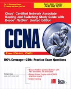
Between the code table at the top and the routes at the bottom is a line that says Gateway of last resort is not set. This is the default configuration. To define a gateway of last resort, use this command:
![]()
The network number you define is the network the router should access as a last resort. Note that your routing table will need an entry indicating how to reach this default network, like a next-hop address. This is typically done via a static route.
Use an address and subnet mask of 0.0.0.0 0.0.0.0 when creating a default route. This is used when no other specific route is available to a destination within the routing table. The gateway of last resort is defined with the ip default-network command.
Note the static route to 198.10.1.0 via 161.44.192.2 and that the gateway of last resort is not set in the previous example of the show ip route output. Next, configure a default network of 198.10.1.0:
![]()
When re-examining the routing table, it changes to this:

The gateway of last resort is now set as 161.44.192.2.

The ip default-gateway command and the ip default-network command function differently. The former is only used when the IOS device has IP routing disabled: when this is done, the ip default-gateway command defines the default router to use to exit the subnet. The ip route and ip default-network commands are used when the IOS device has IP routing enabled. Specific routes in the routing table are used, and if there is no match, then the default network is used.
Default Routes and Distance Vector Protocols
A default route sometimes causes problems for certain routing protocols. A routing protocol can fall under two additional categories: classful and classless. Examples of classful protocols include RIPv1 and IGRP (no longer supported by Cisco). Examples of classless protocols include RIPv2, Open Shortest Path First (OSPF), Enhanced Interior Gateway Routing Protocol (EIGRP), Intermediate System-Intermediate System (IS-IS), and Border Gateway Protocol (BGP).
A classful routing protocol understands only class subnets. For instance, if you have 192.168.1.0/23 in a routing update, a classful routing protocol wouldn’t understand it, since a Class C network requires 24 bits of network numbers. This can create problems with a default route, which has a /0 mask.
Also, when a classful router advertises a route out its interface, it does not include the subnet mask. For example, you might have 192.168.1.1/26 configured on your router’s interface, and the router receives a routing update with 192.168.1.0. With a classful routing protocol, the router will comprehend subnet masks only for network numbers configured on its interfaces. In this example, the router assumes that for 192.168.1.0, the only valid mask is /26. Therefore, if the router sees 192.168.1.0/26 as the network number, but the network is really 192.168.1.0/27, a lot of routing confusion results.
Classless protocols, on the other hand, do not have any issues accepting routing updates with any bit value for a subnet mask. However, for classful protocols, you must configure the following command to accept nonconforming subnet masks, such as a default route:
![]()
This command is also used to deal with discontiguous subnets in a network that is using a classful protocol: subnets separated by a different class network. For example, assume that you have networks 172.16.1.0/24, 172.16.2.0/24, and 172.16.3.0/24. However, a different class network, 192.168.1.0/24, sits between the first two Class B subnets and 172.16.3.0/24. In this situation, the router connected to 172.16.1.0/24 and 172.16.2.0/24, when it receives 172.16.0.0 from the side of the network connected to the discontiguous subnet, will ignore this routing entry.
Remember that when routes cross a class boundary in a classful protocol, the network number is sent as its classful number. Therefore, the router connected to 192.168.1.0/24 and 172.16.3.0/24, when it advertises updates across the 192.168.1.0/24 subnet, will advertise 172.16.0.0—not the actual subnet number. Since the router connected to 172.16.1.0/24 and 172.16.2.0/24 ignores the 172.16.0.0 routing information, it will not be able to reach 172.16.3.0. On top of this problem, even if you have a default route configured, since the router is connected to the 172.16.0.0 subnets, it assumes that 172.16.3.0 must also be connected; if it isn’t in the routing table, then the route cannot be reached. This topic was discussed in Chapter 5.
By using the ip classless command, you are overriding this behavior; you’re allowing your classful router to use a default route to reach discontiguous subnets. Not that this is a recommended design practice, but it does allow you to solve reachability problems for discontiguous subnets.
Classful protocols, such as IP RIPv1, understand only classful subnets—you can apply only one subnet mask to a class address. Classless protocols, such as RIPv2, EIGRP, OSPF, and IS-IS, do not have this restriction. The ip classless command allows a classful protocol to use a default route; omitting this command will cause the router to drop packets that don’t match a specific destination network entry in the routing table.
Static Route Verification and Troubleshooting
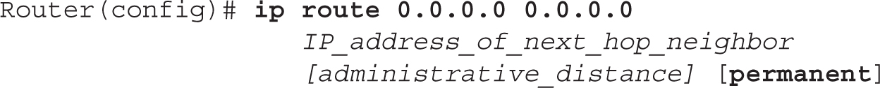
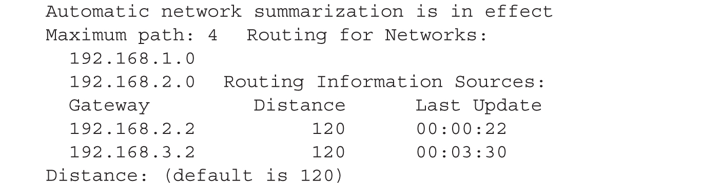
To verify the configuration of IPv4 static and default routes on your router, use the show ip route command:

This command displays the IP routing table on your router and can contain directly connected subnets, static and default routes, and dynamically learned routes from a routing protocol. The top portion of the display for this command has a table of codes. These codes, which describe a type of route that may appear in the routing table, are shown in the first column at the bottom part of the display. In this example, there are two connected routes (C) and two static routes (S). The first static route is treated as a directly connected route, since it was created by specifying the interface to exit the router. The second static route is a default route—the asterisk (*) indicates the gateway of last resort: the path the router should use if no other specific path is available.
Be familiar with the output of the show ip route command and be able to determine, based on a router’s configuration, what routes should appear in a router’s routing table. By default, interfaces (including physical, VLAN, loopback, and subinterfaces) that are operational (up and up) will have their IPv4 networks automatically placed in the IOS’s routing table with a code designation of C.

9.01. The digital resources that accompany this book contain a multimedia demonstration of setting up static routes on a router.

Static Route Configuration
The past few sections have dealt with static routes and their configuration. This exercise will help you reinforce your understanding of this material. You’ll perform this lab using Boson’s NetSim simulator. In this exercise, you’ll set static routes on the two routers (2600-1 and 2600-2). You can find a picture of the network diagram for Boson’s NetSim simulator in the introduction of this book. After starting up the simulator, click the Labs tab at the bottom left of the window. Click the McGraw-Hill Education tab (to the right of the Standard and Custom tabs) at the top left. Next, double-click Exercise 9-1. This will load the lab configuration based on the exercises in Chapter 6.
1. Access the 2600-1 router. Click the Lab Instructions tab and use the drop-down selector for Devices to choose 2600-1; or click the NetMap tab and double-click the 2600-1 device icon.
2. On the 2600-1, verify that the fa0/0 and s0 interfaces are up. If they are not, bring them up. Examine the IP addresses configured on the 2600-1.
Use the show interfaces command to verify your configuration. If fa0/0 and s0 are not up, go into the interfaces (fa0/0 and s0) and enable them using the no shutdown command. Use the show interfaces command to verify that the IP addresses you configured in Chapter 6 are still there.
3. Examine the routing table on the 2600-1.
Use the show ip route command. You should have two connected networks: 192.168.1.0 connected to fa0/0 and 192.168.2.0 connected to s0.
4. Access the 2600-2 router. Click the Lab Instructions tab and use the drop-down selector for Devices to choose 2600-2; or click the NetMap tab and double-click the 2600-2 device icon.
5. On the 2600-2, verify that the fa0/0 and s0 interfaces are up. If not, bring them up. Examine the IP addresses configured on the 2600-2 and look at its routing table.
On the 2600-2, use the show interfaces command to verify your configuration. If fa0/0 and s0 are not up, go into the interfaces (fa0/0 and s0) and enable them using the no shutdown command. Use the show interfaces command to verify that the IP addresses you configured in Chapter 6 are still there.
6. Examine the routing table on the 2600-2 router.
Use the show ip route command. You should have two connected networks: 192.168.3.0 connected to fa0/0 and 192.168.2.0 connected to s0.
7. Test connectivity between Host-1 and the 2600-1.
Click the Lab Instructions tab and use the drop-down selector for Devices to choose Host-1; or click the NetMap tab and double-click the Host-1 device icon. From Host-1, ping the 2600-1: ping 192.168.1.1. The ping should be successful.
8. Test connectivity between Host-3 and the 2600-2.
Click the Lab Instructions tab and use the drop-down selector for Devices to choose Host-3; or click the NetMap tab and double-click the Host-3 device icon. From Host-3, ping the 2600-2 router: ping 192.168.3.1. The ping should be successful.
9. Test connectivity between Host-3 and Host-1.
From Host-3, ping Host-1: ping 192.168.1.10. The ping should fail: there is no route from the 2600-2 to this destination.
10. Look at the 2600-2’s routing table: show ip route. It doesn’t list 192.168.1.0/24.
11. On the 2600-2, configure a static route to 192.168.1.0/24, which is connected to the 2600-1.
Click the Lab Instructions tab and use the drop-down selector for Devices to choose 2600-2; or click the NetMap tab and double-click the 2600-2 device icon. Configure a static route to reach 192.168.1.0/24 via the 2600-1 router. Configure the static route: configure terminal, ip route 192.168.1.0 255.255.255.0 192.168.2.1, and end.
12. View the routing table on the 2600-2 router.
View the connected and static routes: show ip route. Make sure that 192.168.1.0/24 shows up in the routing table as a static route (S).
13. On the 2600-1, configure a static route to 192.168.3.0/24, which is connected to the 2600-2.
Click the Lab Instructions tab and use the drop-down selector for Devices to choose 2600-1; or click the NetMap tab and double-click the 2600-1 device icon. Configure the static route: configure terminal, ip route 192.168.3.0 255.255.255.0 192.168.2.2, and end.
14. View the routing table on the 2600-1.
View the connected and static routes: show ip route. Make sure that 192.168.3.0/24 shows up in the routing table as a static route (S).
15. From Host-3, ping the fa0/0 interface of the 2600-1.
Click the Lab Instructions tab and use the drop-down selector for Devices to choose Host-3; or click the NetMap tab and double-click the Host-3 device icon. Access Host-3 and ping the fa0/0 interface of the 2600-1 router: ping 192.168.1.1. The ping should be successful.
16. From Host-3, ping Host-1.
Ping Host-1: ping 192.168.1.10. The ping should be successful.
Now you should be more comfortable with configuring static routes.
Basic IP and Routing Troubleshooting
This chapter has covered the basics of routers and routing. This exercise is a troubleshooting exercise and is different from the other exercises you have performed so far. In previous exercises, you were given a configuration task. In this exercise, the network is already configured; however, three problems exist in this network and you’ll need to find and fix them to make it operate correctly. All of these problems deal with IP (layer 3) connectivity.
You’ll perform this exercise using Boson’s NetSim simulator. You can find a picture of the network diagram for Boson’s NetSim simulator in the introduction of this book. The addressing scheme is the same. After starting up the simulator, click the Labs tab at the bottom left of the window. Click the McGraw-Hill Education tab (to the right of the Standard and Custom tabs) at the top left. Next, double-click Exercise 9-2. This will load the lab configuration based on the exercises in Chapters 6 and static routing (with problems, of course).
Let’s start with your problem: Host-1 cannot ping Host-3. Your task is to find the three problems causing this and fix them. You should try this troubleshooting process on your own first; if you have problems, come back to the steps and solutions provided here.
1. Use ping to test connectivity from Host-1 to Host-3.
Click the Lab Instructions tab and use the drop-down selector for Devices to choose Host-1; or click the NetMap tab and double-click the Host-1 device icon. On Host-1, ping Host-3: ping 192.168.3.10. Note that the ping fails.
2. Examine the IP configuration on Host-1.
Execute ipconfig /all. Make sure the IP addressing information is correct: IP address of 192.168.1.10, subnet mask of 255.255.255.0, and default gateway address of 192.168.1.1.
3. Test connectivity from Host-1 to its default gateway by using ping.
Ping the default gateway address: ping 192.168.1.1. The ping should be successful, indicating that at least layer 3 is functioning between Host-1 and the 2600-1.
4. Verify Host-3’s IP configuration.
Click the Lab Instructions tab and use the drop-down selector for Devices to choose Host-3; or click the NetMap tab and double-click the Host-3 device icon. Examine the IP configuration on Host-3 by executing ipconfig /all. Make sure the IP addressing information is correct: IP address of 192.168.3.10, subnet mask of 255.255.255.0, and default gateway address of 192.168.3.1.
5. Test connectivity from Host-3 to its default gateway by using ping.
Ping the default gateway address: ping 192.168.3.1. The ping should fail, indicating that there is a problem between Host-3 and the 2600-2. In this example, assume layer 2 is functioning correctly; therefore, it must be a problem with the 2600-2.
6. Check the 2600-2’s IP configuration.
Click the Lab Instructions tab and use the drop-down selector for Devices to choose 2600-2; or click the NetMap tab and double-click the 2600-2 device icon. From the 2600-2, ping Host-3: ping 192.168.3.10. The ping should fail. Examine the interface on the 2600-2: show interface fa0/0. The interface is disabled, but it has the correct IP address: 192.168.3.1. Enable the interface: configure terminal, interface fa0/0, no shutdown, and end. The interface should come up. Retry the ping test: ping 192.168.3.10. The ping should be successful.
7. Access Host-1 and retry pinging Host-3.
Click the Lab Instructions tab and use the drop-down selector for Devices to choose Host-1; or click the NetMap tab and double-click the Host-1 device icon. Test connectivity to Host-3: ping 192.168.3.10. The ping should still fail. So far, there is connectivity within 192.168.1.0 and 192.168.3.0, but there is still a problem between these two networks.
8. Check the interface statuses on the 2600-1 and verify connectivity to the 2600-2.
Click the Lab Instructions tab and use the drop-down selector for Devices to choose 2600-1; or click the NetMap tab and double-click the 2600-1 device icon. Check the status of the interfaces: show ip interface brief. Notice that the fa0/0 and s0 interfaces are both up. Try pinging the 2600-2’s s0 interface: ping 192.168.2.2. The ping fails. Examine CDP information that the 2600-1 has learned about the 2600-2: show cdp entry 2600-2. Notice that the 2600-2 has no IP address.
9. Fix the IP addressing problem on the 2600-2 and retest connectivity across the serial connection.
Click the Lab Instructions tab and use the drop-down selector for Devices to choose 2600-2; or click the NetMap tab and double-click the 2600-2 device icon. Fix the IP address: configure terminal, interface s0, ip address 192.168.2.2 255.255.255.0, and end. Retest the connection to the 2600-1: ping 192.168.2.1. The ping should be successful.
10. Examine the routing table on the 2600-2 and verify that 192.168.1.0/24 shows up as a static route.
Examine the routing table: show ip route. As you can see, 192.168.1.0 shows up as a static route and points to 192.168.2.1.
11. Access Host-3 and try connectivity between its default gateway and the 2600-1 router.
Click the Lab Instructions tab and use the drop-down selector for Devices to choose Host-3; or click the NetMap tab and double-click the Host-3 device icon. Test the connection to the 2600-2: ping 192.168.3.1. The ping should be successful, considering you already tested it. Test connectivity to the 2600-1: ping 192.168.2.1. The ping should fail. This presents an interesting problem. Host-1 can ping the 2600-1. The 2600-1 can ping the 2600-2. Host-3 can ping the 2600-2. Therefore, on a hop-by-hop basis, you have IP connectivity. And the 2600-2 can even ping Host-1, indicating that some routing functioning is working.
12. Access the 2600-1 router and examine its routing table. Fix the problem.
Click the Lab Instructions tab and use the drop-down selector for Devices to choose 2600-1; or click the NetMap tab and double-click the 2600-1 device icon. Examine the routing table: show ip route. Does the 2600-1 know how to reach 192.168.3.0/24? It does not. The 2600-2 router could ping Host-1 since the 2600-1 router is directly connected to these segments, but any traffic from the 2600-1 to 192.168.3.0/24 will fail since the router doesn’t have a path. Add a static route to 192.168.3.0/24: configure terminal, ip route 192.168.3.0 255.255.255.0 192.168.2.2, and end. Test connectivity to Host-3: ping 192.168.3.10. The ping should be successful.
13. Now test connectivity between Host-1 and Host-3.
Click the Lab Instructions tab and use the drop-down selector for Devices to choose Host-1; or click the NetMap tab and double-click the Host-1 device icon. Test connectivity to Host-3: ping 192.168.3.10. The ping should be successful.
You should sharpen your basic IP troubleshooting skills for the exam, as demonstrated in this exercise.
You should now feel comfortable troubleshooting routers that are using static routes for routing.
IPv6 Static Route Configuration
The fundamentals of IPv6 were covered previously during your CCENT studies. This and the next two chapters will focus on routing IPv6 traffic. This chapter will quickly review the configuration of IPv6 on an IOS device and introduce you to configuring IPv6 static routes.
Enabling IPv6 and Assigning Addresses
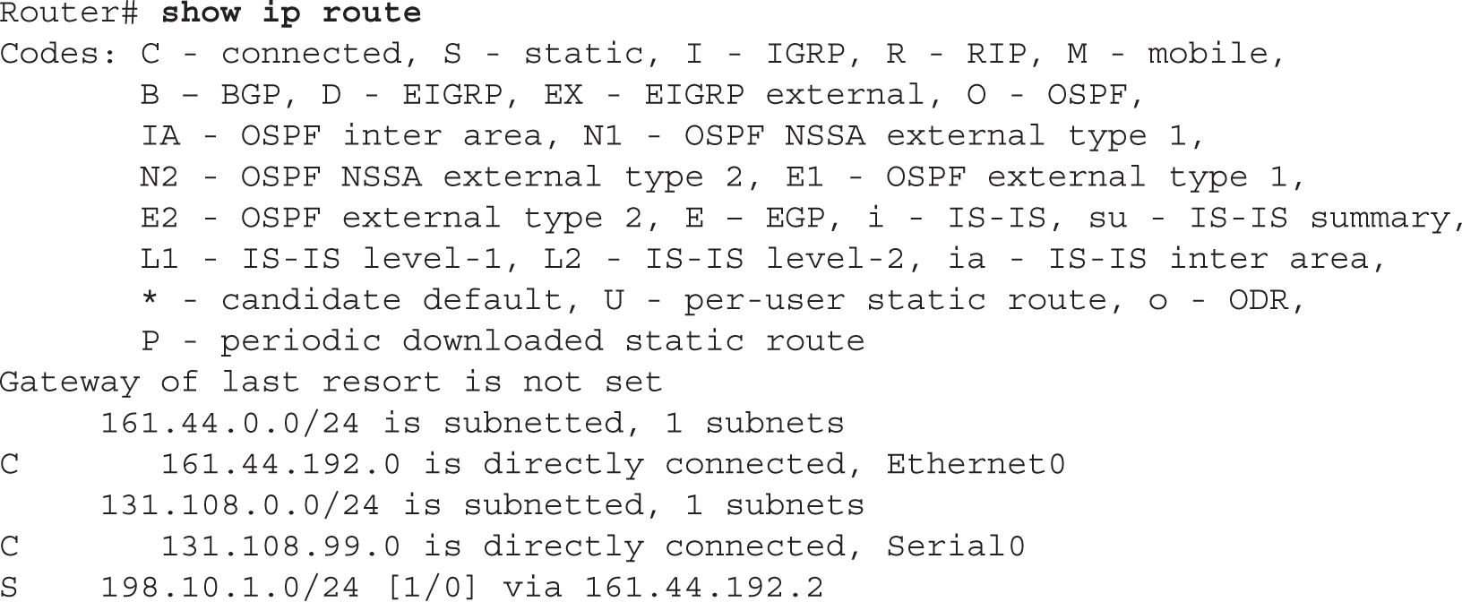
To use IPv6 on your router, you must, at a minimum, enable the protocol and assign IPv6 addresses to your interfaces, like this:
The ipv6 unicast-routing command globally enables IPv6 and must be the first IPv6 command executed on the router. The ipv6 address command assigns the prefix, the length, and the use of EUI-64 to assign the interface ID. Optionally, you can omit the eui-64 parameter and configure the entire IPv6 address.
To use stateless autoconfiguration, use the following configuration:

If a default router is selected on this interface, the default parameter causes a default route to be installed using that default router. The default parameter can be specified only on one interface.
You can use the show ipv6 interface command to verify an interface’s configuration. Here’s an example configuration, with its verification:

In this example, notice that the link-local address is FE80::207:EFF:FE46:4070. Also notice the global address: 2001:1CC1:DDDD:2:207:EFF:FE46:4070.
You enable IPv6 with the ipv6 unicast-routing command—this enables forwarding of IPv6 packets. Once IPv6 is enabled, you must create IPv6 addresses on the interfaces with the ipv6 address ipv6_address_prefix/prefix_length command for IPv6 traffic to be processed on those interfaces.
You can use the ping and traceroute commands to test connectivity with IPv6. Execute the command and immediately follow it with the IPv6 address you want to test. Here’s an example:

Remember that you can only test connectivity to link-local addresses in the same VLAN—however, you can test access to global addresses in the same or different VLANs.
9.02. The digital resources that accompany this book contain a multimedia demonstration of enabling IPv6 and configuring IPv6 on a router’s interfaces.
IPv6 Static Routing
Configuring an IPv6 static route is similar to configuring an IPv4 static route. Here is the syntax:
![]()
The prefix is the network number you want to reach, with the corresponding number of bits of the network number. For a default route, use ::/0 as the prefix.
To view the IPv6 routes in the routing device’s routing table, use the show ipv6 route command:

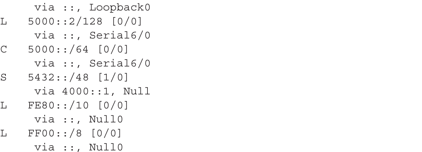
The formatting of the output is slightly different from that of the IPv4 routing table. Like the IPv4 routing table, a C indicates a directly connected route (network) and an S indicates a static route. The L is new—it’s a host route. This is an IPv6 address of a host connected to that interface. Also notice that you can see the administrative distance and metric for each route ([X/Y]).
CERTIFICATION OBJECTIVE 9.02
Dynamic Routing Protocol Basics
Before learning how to configure a dynamic routing protocol such as RIP, consider some basic configuration tasks that are required no matter what dynamic routing protocol you are running. You need to perform two basic steps when setting up IP routing on your router:
![]() Enable the routing protocol.
Enable the routing protocol.
![]() Assign IP addresses to your router’s interfaces.
Assign IP addresses to your router’s interfaces.
Remember the two steps required to set up IP routing on a router.
Note that the order of these tasks is not important. You already know how to configure an IP address on the router’s interface: this was discussed in Chapter 6. The following sections cover the first bullet point in more depth.
The router Command
Enabling an IP routing protocol is a two-step process. First, you must go into Router Subconfiguration mode. This mode determines the routing protocol that you’ll be running. Within this mode, you’ll configure the characteristics of the routing protocol. To enter the routing protocol’s configuration mode, use the following command:

The router command is used to access the routing protocol that you want to configure; it doesn’t enable it. If you are not sure of the name of the routing protocol that you want to enable, use the context-sensitive help feature:
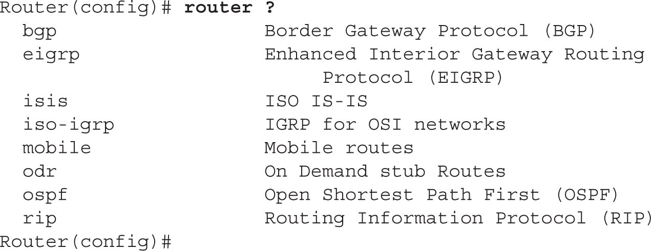
As you can see from the context-sensitive help output, you have a lot of IP routing protocols at your disposal.
One important item to point out is that the router command doesn’t turn on the routing protocol. This process is done in the protocol’s Router Subconfiguration mode, indicated by the (config-router) prompt.
The network Command
Once in the routing protocol, you need to specify what interfaces are to participate in the routing process. By default, no interfaces participate in the routing process. To specify which interfaces will participate, use the network Router Subconfiguration mode command:
![]()
As soon as you enter a network number, the routing process becomes active. For distance vector protocols such as RIPv1, you need to enter only the Class A, B, or C network number or numbers that are associated with your interface or interfaces. In other words, if you have subnetted 192.168.1.0 with a subnet mask of 255.255.255.192 (/26) and you have subnets 192.168.1.0/26, 192.168.1.64/26, 192.168.1.128/26, and 192.168.1.192/26, you don’t need to enter each specific subnet. Instead, just enter 192.168.1.0, and this will accommodate all interfaces that are associated with this Class C network. If you specify a subnet, the router will convert it to the class address because RIP is a classful protocol.
Let’s take a look at a simple example of the configuration, shown in Figure 9-1. This example focuses on the configuration of the network commands, assuming that the routing protocol is a classful protocol, such as RIPv1. In this example, the router is connected to a Class B network (172.16.0.0) and a Class C network (192.168.1.0), both of which are subnetted.
FIGURE 9-1 Simple network example

Assume that you forgot that you need to enter only the classful network numbers and you entered the subnetted values instead, like this:

When entering your network statements, you need to include any network that is associated with your router’s interfaces; if you omit a network, your router will not include the omitted interface in the routing process. As you can see from the preceding example, all the subnets were included. Remember, however, that the router requires only that you enter the class addresses. If you were to execute a show running-config command, you would not see the four networks just listed, but only the Class B and C network numbers. You shouldn’t worry about this; it’s just that you entered more commands than were necessary. In reality, you needed to enter only these two network commands:

Both ways of entering your statements are correct, but the latter is what the router will use if you type in all of the specific subnets.
On the exam, you should enter the class networks instead of the subnets on the simulator questions that deal with classful routing protocols. Remember that the simulator is just that—a simulator. It’s not a full-functioning IOS router.
9.03. The digital resources that accompany this book contain a multimedia demonstration of an introduction to basic IP routing protocol configuration.
CERTIFICATION OBJECTIVE 9.03
RIP
IP RIP comes in two different versions: 1 and 2. Version 1 is a distance vector protocol and is defined in RFC 1058. Version 2 is an enhanced version of RIPv1 and is defined in RFCs 1721 and 1722. The CCNA exam now primarily focuses on version 2. However, you still need to know a few things about RIPv1, specifically its characteristics. This section covers the basics of configuring and troubleshooting your network using IP RIP.
RIP Operation
As you’ll recall from Chapter 4, RIP is a distance vector protocol. RIP is an old protocol and therefore is very stable—in other words, Cisco doesn’t do that much development on the protocol, unlike other, more advanced protocols. Therefore, you can feel safe that when you upgrade your IOS to a newer version, RIP will function the same way it did in the previous release. This section includes brief overviews of both versions of RIP.
RIPv1
RIPv1 uses local broadcasts to share routing information. These updates are periodic in nature, occurring, by default, every 30 seconds, with a hold-down period of 180 seconds. Both versions of RIP use hop count as a metric, which is not always the best metric to use. For instance, if you had two paths to reach a network, where one was a two-hop Ethernet connection and the other was a one-hop 64-Kbps WAN connection, RIP would use the slower 64-Kbps connection because it has a lesser accumulated hop-count metric. You have to remember this little tidbit when looking at how RIP will populate your router’s routing table. To prevent packets from circling around a loop forever, both versions of RIP solve counting to infinity by placing a hop-count limit of 15 hops on packets. Any packet that reaches the 16th hop will be dropped.
And as mentioned in the previous section, RIPv1 is a classful protocol. This is important for configuring RIP and subnetting your IP addressing scheme: you can use only one subnet mask value for a given Class A, B, or C network. For instance, if you have a Class B network such as 172.16.0.0, you can subnet it with only one mask. As an example, you couldn’t use 255.255.255.0 and 255.255.255.128 on 172.16.0.0—you can choose only one.
IOS routing devices support four equal-cost paths to a single destination in their routing tables by default. The maximum number of equal-cost paths that can be configured depends on the particular routing protocol that is used.
Another interesting feature is that RIP supports up to six equal-cost paths to a single destination, where all six paths can be placed in the routing table and the router can load-balance across them. The default is actually four paths, but this can be increased up to a maximum of six. Remember that an equal-cost path is where the metric for the multiple paths to a destination is the same. RIP will not load-balance across unequal-cost paths.
Figure 9-2 illustrates equal-cost-path load balancing. In this example, RouterA has two equal-cost paths to 10.0.0.0 (with a hop count of 1) via RouterB and RouterC. Putting both of these paths in RouterA’s routing table offers two advantages:
FIGURE 9-2 Equal-cost-path load balancing

![]() The router can perform load balancing to 10.0.0.0, taking advantage of the bandwidth on both of these links.
The router can perform load balancing to 10.0.0.0, taking advantage of the bandwidth on both of these links.
![]() Convergence is sped up if one of the paths fails. For example, if the connection between RouterA and RouterB fails, RouterA can still access network 10.0.0.0 via RouterC and has this information in its routing table; therefore, convergence is instantaneous.
Convergence is sped up if one of the paths fails. For example, if the connection between RouterA and RouterB fails, RouterA can still access network 10.0.0.0 via RouterC and has this information in its routing table; therefore, convergence is instantaneous.
For these two reasons, many routing protocols support parallel paths to a single destination. Some protocols, such as EIGRP, even support unequal-cost-path load balancing, which is discussed in Chapter 11.
IP RIPv1, a classful protocol, broadcasts updates every 30 seconds and has a hold-down period of 180 seconds. Hop count is used as a metric: the path or paths with the least accumulated hop count are used and placed in the routing table.
RIPv2
One thing you should keep in the back of your mind when dealing with RIPv2 is that it is based on RIPv1 and is, at heart, a distance vector protocol with routing enhancements built into it. Therefore, it is commonly called a hybrid protocol. You read about some of the characteristics that both versions of RIP have in common in the preceding section. This section focuses on the characteristics unique to RIPv2.
One major enhancement to RIPv2 pertains to how it deals with routing updates. Instead of using broadcasts, RIPv2 uses multicasts: updates are advertised to 224.0.0.9, which all RIPv2 routers will process. And to speed up convergence, RIPv2 supports triggered updates—when a change occurs, a RIPv2 router will immediately propagate its routing information to its connected neighbors.
A second major enhancement in RIPv2 is that it is a classless protocol. RIPv2 supports variable-length subnet masking (VLSM), which allows you to use more than one subnet mask for a given class network number. VLSM allows you to maximize the efficiency of your addressing design and summarize routing information to create very large, scalable networks. VLSM is discussed in Chapter 7.
Even with all of its advanced characteristics, RIPv2 is still, at heart, a distance vector protocol. It uses hop count as a metric, supports the same solutions to solve routing loop problems, has a 15-hop-count limit, and shares other characteristics of RIPv1. RIPv2 is a hybrid protocol, based on RIPv1. It uses multicasts to disseminate routing information and supports triggered updates. Unlike RIPv1, RIPv2 supports VLSM (advertises subnet masks with associated network numbers), which allows you to summarize routing information, and authentication of routing updates. Otherwise, its characteristics are like those of RIPv1.
As a third enhancement, RIPv2 supports authentication. You can restrict what routers you want to participate in RIPv2. This is accomplished using a clear-text or hashed password value.
Cisco hash values aren’t the most secure security measures on the planet, and cracking any password assigned to a Cisco device is relatively easy (even MD5 with a password-cracking program). You should still assign these kinds of passwords as an added level of security, but don’t rely on them totally: physical security is still paramount.
RIP Configuration
As you will see in this section, configuring RIP is an easy and straightforward process. The basic configuration of RIP involves the following two commands:

As explained in the preceding section, RIPv1 is classful and RIPv2 is classless. However, whenever you configure either version of RIP, the network command assumes classful: You need to enter only the Class A, B, or C network number, not the subnets, as was discussed earlier in this chapter. If you refer back to Figure 9-1, the router’s RIPv1 configuration would look like this:

Use the router rip and network commands to configure RIP routing. Remember to put the class address (not the subnetted network number) in the network statement.
9.04. The digital resources that accompany this book contain a multimedia demonstration of a basic RIP configuration on a router.
Specifying RIP Version 1 and 2
By default, the IOS accepts both RIPv1 and RIPv2 routing updates; however, it generates only RIPv1 updates. You can configure your router to
![]() Accept and send RIPv1 only
Accept and send RIPv1 only
![]() Accept and send RIPv2 only
Accept and send RIPv2 only
![]() Use a combination of the two, depending on your interface configuration
Use a combination of the two, depending on your interface configuration
To accomplish either of the first two items in the list, you need to set the version in your RIP configuration:

When you specify the appropriate version number, your RIP routing process will send and receive only the version packet type that you configured.
You can also control which version of RIP is running on an interface-by-interface basis. For instance, suppose a bunch of new routers at your site support both versions and a remote office understands only RIPv1. In this situation, you can configure your routers to generate RIPv2 updates on all their LAN interfaces, but for the remote-access connection at the corporate site, you could set the interface to run only RIPv1.
To control which version of RIP should handle generating updates on an interface, use the following configuration:

With the ip rip send command, you can control which version of RIP the router should use on the specified interface when generating RIP updates. You can specify version 1 or 2, or you can specify both.
To control what version of RIP should be used when receiving RIP updates on a particular interface, use the following configuration:

Unless you need to run RIPv1 because of backward compatibility with an older router or host running RIP, you should use version 2 because of some of its enhancements over version 1, such as classless routing, multicasts, and triggered updates.
9.05. The digital resources that accompany this book contain a multimedia demonstration of RIPv2 configuration on a router.
Configuration Example
Let’s use a simple network example, shown in Figure 9-3, to illustrate configuring RIPv2. Here’s RouterA’s configuration:
FIGURE 9-3 RIPv2 configuration example


Here’s RouterB’s configuration:

As you can see, configuring RIPv2 is very easy.
Make sure you know how to place a basic configuration on a router, including IP addressing, as well as how to set up a routing protocol, like RIPv2. You should also be familiar with verifying and troubleshooting your configuration.
RIP Verification and Troubleshooting
Once you have configured IP RIP, a variety of commands are available to view and troubleshoot your RIP configuration and operation:
![]()
clear ip route
![]()
show ip protocols
![]()
show ip route
![]()
debug ip rip
The following sections cover these commands in more depth.
The clear ip route Command
The clear ip route * command is a Privileged EXEC mode command. This command clears and rebuilds the IP routing table. Any time you make a change to a routing protocol, you should clear and rebuild the routing table with this command. You can replace the asterisk (*) with a specific network number; if you choose to do so, this will only clear the specified route from the routing table. Note that the clear command clears only routes learned from a routing protocol (dynamic routes); static and directly connected routes cannot be cleared from the routing table using the clear command. Static routes must be cleared manually using the no ip route command, and directly connected routes are persistent and cannot be removed from the routing table unless the interface they are associated with is not operational.
The show ip protocols Command
The show ip protocols command displays all the IP routing protocols, including RIP, which you have configured and are running on your router. Here’s an example of this command:
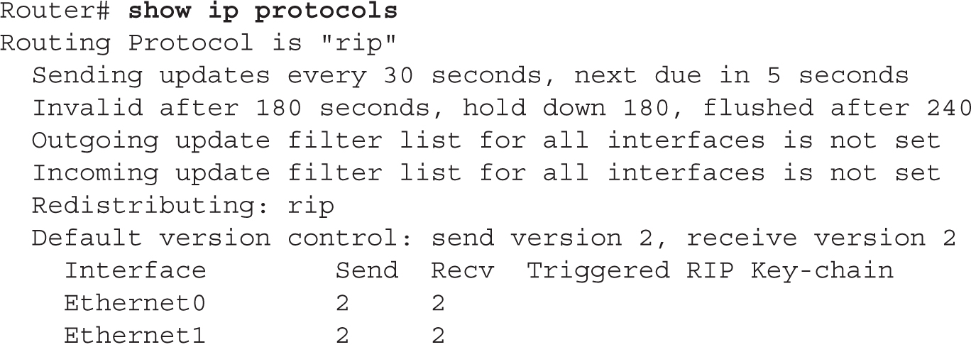
In this example, RIPv2 is running on the router. The routing update interval is 30 seconds, with the next update being sent in 5 seconds. You can see that two interfaces are participating: Ethernet0 and Ethernet1. On these interfaces, RIPv2 is being used to generate and receive updates on these two interfaces. You can see the two networks specified with the network commands: 192.168.1.0 and 192.168.2.0. In this example, this router received an update 22 seconds ago from a neighboring router: 192.168.2.2. For the second gateway, 192.168.3.2, the router hasn’t seen an update from it in 210 seconds. Given that the flush timer is 240 seconds, if the local router doesn’t receive an update from 192.168.3.2 within 30 seconds, 192.168.3.2 and its associated routes are removed from the local router (flushed). And last, the default administrative distance of RIP is 120.
RIP advertises routes every 30 seconds. Its hold-down period is 180 seconds, and its flush period is 240 seconds. Be familiar with the output of the show ip protocols command: the version of RIP and when routes are flushed.
9.06. The digital resources that accompany this book contain a multimedia demonstration of the show ip protocols command for RIP on a router.
The show ip route Command
Your router keeps a list of the best paths to destinations in a routing table. A separate routing table is kept for each routed protocol. For instance, if you are running IP and IPX, your router will have two routing tables: one for each. However, if you are running two routing protocols for a single routed protocol, such as IP RIP and EIGRP, your router will have only one routing table for IP, with both sets of routes, possibly, in the same table.
Remember the output of the show ip route command for the RIP routing protocol, including being able to identify the administrative distance and metric values.
To view the routing table, use the show ip route command. Here’s an example of a RIPv2 router’s table:


In this example, you can see that two types of routes are in the routing table: R is for RIP and C is for a directly connected route. For the RIP entries, you can see two numbers in brackets: the administrative distance of the route and the metric. For instance, 172.16.2.0 has an administrative distance of 120 and a hop count of 1. Following this information is the neighboring RIP router that advertised the route (172.16.1.2), how long ago an update for this route was received from the neighbor (21 seconds), and on which interface this update was learned (Ethernet0).
9.07. The digital resources that accompany this book contain a multimedia demonstration of the show ip route command for RIP on a router.
The debug ip rip Command
Remember that the show commands show a static display of what the router knows, and they sometimes don’t display enough information concerning a specific issue or problem. For instance, you might be looking at your routing table with the show ip route command and expect a certain RIP route to appear from a connected neighbor, but this network is not shown. Unfortunately, the show ip route command won’t tell you why a route is or isn’t in the routing table. However, you can resort to debug commands to assist you in your troubleshooting.
For more detailed troubleshooting of IP RIP problems, you can use the debug ip rip command, shown here:

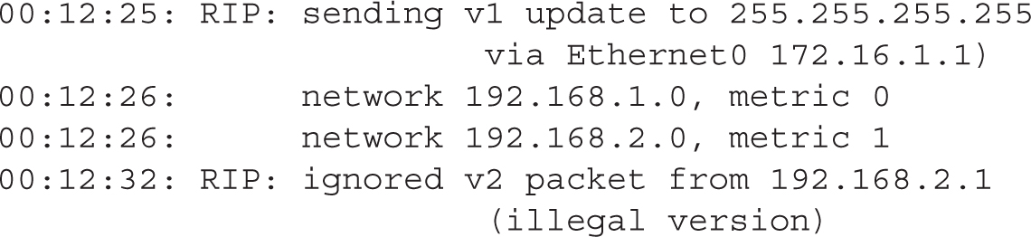
This command displays the routing updates sent and received on the router’s interfaces. In this code example, the router received a V1 update from 192.168.1.2 on Serial0. This update contained one network, 192.168.2.0, indicating that this network is reachable from this and the advertising routers. After this update, you can see that your router generated a RIP update (local broadcast—255.255.255.255) on its Ethernet0 interface. This update contains two networks: 192.168.1.0 and 192.168.2.0. Also notice the metrics associated with these routes: 192.168.1.0 is connected to this router, while 192.168.2.0 is one hop away. When the neighboring router connected to Ethernet0 receives this update, it will increment the hop count by 1 for each route in the update.
Be familiar with the output of the debug ip rip command to troubleshoot problems with RIP, such as a mismatch in the RIP versions. Remember that debug commands can create performance problems on routers and should be used only for troubleshooting and then disabled.
If the two routers are running different RIP versions—v1 and v2—you’ll see output like the following on your router when running the preceding debug command:
When using debug commands, you must be at Privileged EXEC mode. To disable a specific debug command, negate it with the no parameter. To turn off debugging for all debug commands, use either the undebug all or no debug all command.
9.08. The digital resources that accompany this book contain a multimedia demonstration of the debug ip rip command for RIP on a router.
Configuring RIP
The past few sections dealt with configuring RIP on a router. This exercise will help you reinforce your understanding of the material for setting up and troubleshooting RIP. You’ll perform this lab using Boson’s NetSim simulator. You can find a picture of the network diagram for Boson’s NetSim simulator in the introduction of this book. In this exercise, you set IP RIPv1 on the two routers (2600-1 and 2600-2). After starting up the simulator, click the Labs tab at the bottom left of the window. Click the McGraw-Hill Education tab (to the right of the Standard and Custom tabs) at the top left. Next, double-click Exercise 9-3. This will load the lab configuration based on the exercises in Chapter 6.
1. On the 2600-1, verify that the fa0/0 and s0 interfaces are up. If not, bring them up. Click the Lab Instructions tab and use the drop-down selector for Devices to choose 2600-1; or click the NetMap tab and double-click the 2600-1 device icon. On the 2600-1, use the show interfaces command to verify your configuration. If fa0/0 and s0 are not up, go into the interfaces (fa0/0 and s0) and enable them: configure terminal, interface type [slot_#/]port_#, no shutdown, and end.
2. Examine the IP addresses configured on the 2600-1.
Use the show ip interface brief command to verify that the IP addresses you configured in Chapter 6 are still there.
3. Examine the routing table on the 2600-1.
Use the show ip route command. You should have two connected networks: 192.168.1.0 connected to fa0/0 and 192.168.2.0 connected to s0.
4. On the 2600-2, verify that the fa0/0 and s0 interfaces are up. If not, bring them up.
Click the Lab Instructions tab and use the drop-down selector for Devices to choose 2600-2; or click the NetMap tab and double-click the 2600-2 device icon. On the 2600-2, use the show interfaces command to verify your configuration. If fa0/0 and s0 are not up, go into the interfaces (fa0/0 and s0) and enable them: configure terminal, interface type port_#, no shutdown, and end. Use the show interfaces command to verify your interface configuration.
5. Examine the IP addresses configured on the 2600-2.
Use the show ip interface brief command to verify that the IP addresses you configured in Chapter 6 are still there.
6. Examine the routing table on the 2600-2.
Use the show ip route command. You should have two connected networks: 192.168.3.0 connected to fa0/0 and 192.168.2.0 connected to s0.
7. Test connectivity between Host-1 and the 2600-1.
Click the Lab Instructions tab and use the drop-down selector for Devices to choose Host-1; or click the NetMap tab and double-click the Host-1 device icon. From Host-1, ping the 2600-1 router (the default gateway): ping 192.168.1.1. The ping should be successful.
8. Test connectivity between Host-3 and the 2600-2.
Click the Lab Instructions tab and use the drop-down selector for Devices to choose Host-3; or click the NetMap tab and double-click the Host-3 device icon. From the Host-3, ping the 2600-2 router (the default gateway): ping 192.168.3.1. The ping should be successful.
9. Test connectivity between Host-3 and Host-1.
From the Host-3, ping Host-1: ping 192.168.1.10. The ping should fail. Why? There is no route from the 2600-2 to this destination. (Look at the 2600-2’s routing table: it doesn’t list 192.168.1.0/24.)
10. Access the 2600-2 and examine the routing table to see why the ping failed.
Click the Lab Instructions tab and use the drop-down selector for Devices to choose 2600-2; or click the NetMap tab and double-click the 2600-2 device icon. Examine the routing table: show ip route. Notice that it doesn’t list 192.168.1.0/24, which explains why Host-3 can’t reach Host-1.
11. Enable RIPv1 on the 2600-1 router.
Click the Lab Instructions tab and use the drop-down selector for Devices to choose 2600-1; or click the NetMap tab and double-click the 2600-1 device icon. On the 2600-1, execute the following: configure terminal, router rip, network 192.168.1.0, network 192.168.2.0, and end.
12. Enable RIPv1 on the 2600-2 router.
Click the Lab Instructions tab and use the drop-down selector for Devices to choose 2600-2; or click the NetMap tab and double-click the 2600-2 device icon. On the 2600-2, execute the following: configure terminal, router rip, network 192.168.2.0, network 192.168.3.0, and end.
13. On the 2600-1, verify the operation of RIP.
Click the Lab Instructions tab and use the drop-down selector for Devices to choose 2600-1; or click the NetMap tab and double-click the 2600-1 device icon. Use the show ip protocols command to make sure that RIP is configured—check for the neighboring router’s IP address. Use the show ip route command and look for the remote LAN network number as a RIP (R) entry in the routing table. On the 2600-1, you should see 192.168.3.0, which was learned from the 2600-2.
14. On the 2600-2, verify the operation of RIP.
Click the Lab Instructions tab and use the drop-down selector for Devices to choose 2600-2; or click the NetMap tab and double-click the 2600-2 device icon. Use the show ip protocols command to make sure that RIP is configured—check for the neighboring router’s IP address. Use the show ip route command and look for the remote LAN network number as a RIP (R) entry in the routing table. On the 2600-2, you should see 192.168.1.0, which was learned from the 2600-1.
15. On Host-1, test connectivity to Host-3.
Click the Lab Instructions tab and use the drop-down selector for Devices to choose Host-1; or click the NetMap tab and double-click the Host-1 device icon. On Host-1, test connectivity: ping 192.168.3.10. The ping should be successful.
Basic RIP Troubleshooting
This exercise is a troubleshooting exercise and is similar to Exercise 9-3, in which you were given a configuration task to set up RIP. In this exercise, the network is already configured; however, three problems exist in this network and you’ll need to find and fix them in order for the network to operate correctly. All of these problems deal with IP (layer 3) connectivity. You’ll perform this exercise using Boson’s NetSim simulator. You can find a picture of the network diagram for Boson’s NetSim simulator in the introduction of this book. The addressing scheme is the same as that configured in Chapter 6. After starting up the simulator, click the Labs tab at the bottom left of the window. Click the McGraw-Hill Education tab (to the right of the Standard and Custom tabs) at the top left. Next, double-click Exercise 9-4. This will load the lab configuration based on Chapter 6’s exercises (with problems, of course).
Let’s start with your problem: Host-1 cannot ping Host-3. Your task is to identify and fix the three issues. In this example, RIPv2 has been preconfigured on the routers. Try this troubleshooting process on your own first; if you have problems, come back to the steps and solutions provided here.
1. Use the ping tool to test connectivity from Host-1 to Host-3.
Click the Lab Instructions tab and use the drop-down selector for Devices to choose Host-1; or click the NetMap tab and double-click the Host-1 device icon. On Host-1, ping Host-3: ping 192.168.3.10. Note that the ping fails.
2. Examine the IP configuration on Host-1.
Execute ipconfig /all. Make sure the IP addressing information is correct: IP address of 192.168.1.10, subnet mask of 255.255.255.0, and default gateway address of 192.168.1.1.
3. Use the ping tool to test connectivity from Host-1 to its default gateway.
Ping the default gateway address: ping 192.168.1.1. The ping should fail, indicating that at least layer 3 is not functioning between Host-1 and the 2600-1.
4. Check the 2600-1’s IP configuration.
Click the Lab Instructions tab and use the drop-down selector for Devices to choose 2600-1; or click the NetMap tab and double-click the 2600-1 device icon. From the 2600-1, ping Host-1: ping 192.168.1.10. The ping should fail. Examine the interface on the 2600-1: show interface fa0/0. The interface is enabled, but it has an incorrect IP address: 192.168.11.1. Fix the IP address: configure terminal, interface fa0/0, ip address 192.168.1.1 255.255.255.0, and end. Verify the IP address: show interface fa0/0.
5. Retest connectivity with ping.
Retry the ping test: ping 192.168.1.10. The ping should be successful. Save the configuration on the router: copy running-config startup-config.
6. Test connectivity from Host-1 to Host-3 with ping, as well as to the default gateway.
Click the Lab Instructions tab and use the drop-down selector for Devices to choose Host-1; or click the NetMap tab and double-click the Host-1 device icon. On Host-1, ping Host-3: ping 192.168.3.10. Note that the ping still fails.
7. Examine Host-3’s IP configuration.
Click the Lab Instructions tab and use the drop-down selector for Devices to choose Host-3; or click the NetMap tab and double-click the Host-3 device icon. Examine the IP configuration on Host-3 by executing ipconfig /all. Make sure the IP addressing information is correct: IP address of 192.168.3.10, subnet mask of 255.255.255.0, and default gateway address of 192.168.3.1.
8. Test connectivity from Host-3 to its default gateway.
Ping the default gateway address: ping 192.168.3.1. The ping should fail, indicating that there is a problem between Host-3 and the 2600-2. In this example, assume layer 2 is functioning correctly; therefore, it must be a problem with the 2600-2.
9. Check the interface statuses and IP configuration on the 2600-2.
Click the Lab Instructions tab and use the drop-down selector for Devices to choose 2600-2; or click the NetMap tab and double-click the 2600-2 device icon. Check the status of the interfaces: show interfaces. Notice that fa0/0 is disabled, but s0 is enabled (up and up). Go into fa0/0 and enable it: configure terminal, interface fa0/0, no shutdown, and end. Verify the status of the fa0/0 interface: show interface fa0/0.
10. Verify connectivity from the 2600-2 to the 2600-1.
Try pinging Host-3: ping 192.168.3.10. The ping should succeed. Try pinging the 2600-1’s s0 interface: ping 192.168.2.1. The ping succeeds.
11. Verify RIP’s configuration on the 2600-2.
Examine the RIP configuration: show ip protocol. You should see RIP as the routing protocol and networks 192.168.2.0 and 192.168.3.0 included. From the output, it looks like RIP is configured correctly on the 2600-2. Save the configuration on the router: copy running-config startup-config.
12. Test connectivity from the 2600-2 to Host-1. Examine the routing table.
Test the connection to Host-1: ping 192.168.1.10. The ping should fail. This indicates a layer 3 problem between the 2600-2 router and Host-1.
13. View the routes in the 2600-2’s routing table.
Examine the routing table: show ip route. Notice that there are only two connected routes (192.168.2.0/24 and 192.168.1.0/24), but no RIP routes.
14. Access the 2600-1 router and examine RIP’s configuration.
Click the Lab Instructions tab and use the drop-down selector for Devices to choose 2600-1; or click the NetMap tab and double-click the 2600-1 device icon. Examine the routing table: show ip protocol. What networks are advertised by the 2600-1? You should see 192.168.1.0 and 192.168.11.0. Obviously, serial0’s interface isn’t included since 192.168.2.0 is not configured.
15. Fix the problem with the 2600-1’s RIP configuration.
Fix this configuration problem: configure terminal, router rip, no network 192.168.11.0, network 192.168.1.0, and end. Examine the routing protocol configuration: show ip protocol.
16. Test connectivity to Host-3 using ping.
Test connectivity to Host-3: ping 192.168.3.10. The ping should be successful. Save the configuration on the router: copy running-config startup-config.
17. Now test connectivity between Host-1 and Host-3.
Click the Lab Instructions tab and use the drop-down selector for Devices to choose Host-1; or click the NetMap tab and double-click the Host-1 device icon. Test connectivity to Host-3: ping 192.168.3.10. The ping should be successful.
Now you should be more comfortable with configuring IP RIP on your IOS router.
You should be familiar with troubleshooting connectivity problems. Look for incorrect static routes, incorrect or missing network commands, running different routing protocols on connected routers, misconfigured addresses on interfaces (addresses in different subnets), no addresses on interfaces, disabled interfaces, different RIP versions on routers, and misconfigured VLANs on switches, for example.
Default Gateway Redundancy
The remainder of this chapter focuses on layer 3 redundancy issues. When you think of layer 3 redundancy, you’re normally dealing with having multiple paths to a destination and using a dynamic routing protocol to find the best or alternative path. This section, however, deals with another type of layer 3 redundancy: default gateways and server load balancing. These are issues typically found at the access and distribution layers (see Chapter 3). I’ll begin by talking about some of the issues of default gateway redundancy and some of the solutions that are available but don’t work very well. The main part of this section deals with Cisco’s Hot Standby Routing Protocol (HSRP), as well as other solutions, such as the Virtual Router Redundancy Protocol (VRRP) and Gateway Load Balancing Protocol (GLBP).
Problems of Traditional Default Gateway Redundancy Solutions
You can easily place two routing devices at the distribution layer of each switch block to provide redundancy for end stations to leave their VLAN. However, this might not provide a true fault-tolerant solution. This is especially true for situations in which end stations do not support a router discovery protocol to learn which routers they can use, or they can’t be configured to use more than one default gateway address.
Proxy ARP Issues
Some end stations can use Proxy ARP to discover the IP address of the default gateway. In this situation, the end station dynamically acquires the IP address and MAC address of the default gateway and sends all its inter-VLAN traffic to this routing device. To begin, the end station doesn’t know how to reach the destination and generates an ARP request for it. Obviously, if the destination is not in the same VLAN, no one responds and the end station assumes that the destination is not reachable. However, a Cisco router can proxy this ARP by sending back its own MAC address to the end station, and the end station can then use the router to send traffic out of the subnet. From the end station’s perspective, it thinks it’s sending traffic directly to the destination, but it’s actually being relayed by the router. On Cisco IOS devices with routing enabled, Proxy ARP is enabled by default on the routing interfaces.
However, a problem arises when the default gateway fails. In this situation, the end station still sends its information to the failed default gateway, where the traffic is dropped. Sometimes a client re-performs the ARP after a lengthy period of time to verify the destination’s (default gateway’s) existence. (At this point, it will have discovered that the default gateway has failed, and then another routing device can perform the proxy.) However, in most implementations of ARP, the end station continues to use the same failed default gateway MAC address unless it is rebooted.
ICMP Router Discovery Protocol Issues
The ICMP Router Discovery Protocol (IRDP) is not a routing protocol like OSPF or RIP, but rather is an extension to ICMP that allows an end station to automatically discover the default gateways connected to the same VLAN. IRDP is covered in RFC 1256. In this environment, the routing devices periodically generate special multicast packets that announce the router’s existence to the clients. This time period is usually between 5 and 10 minutes. Learned information usually has a maximum lifetime of 30 minutes on the client if no more IRDP messages are heard from the advertising routing device. The multicast packet includes the routing device’s address and a lifetime value.
With IRDP, end stations can dynamically discover other routing devices when their primary default gateway fails. However, this might take up to 30 minutes, based on the lifetime value in the original multicast packet from the routing device. And even if you might consider using IRDP with your access layer devices, most end-station IP protocol stacks do not support IRDP.
Routing Protocol Issues
To overcome these two previous problems, you might be able to run a routing protocol on the end station, if the client supports this type of function. With IP, the only routing protocol that most end stations might support is RIP or OSPF. In RIP or OSPF, the end station could make intelligent decisions about which layer 3 routing device to use to access other subnets. However, the issue with RIP is that its convergence is very slow—it could take up to 180 seconds before an alternative routing device is chosen when the current primary routing device fails. With TCP sessions, this would cause a timeout. Because of this, as well as all the additional overhead that RIP creates, this solution is not very desirable for your end stations—and this assumes that your end stations and other network devices support a routing protocol such as RIP.
User Device Issues
In most campus environments, end stations are assigned a single IP address for the default gateway (which is usually done via DHCP). In this environment, if the routing device (default gateway) were to fail, the end station would lose its capability to access other networking devices outside of its VLAN. Unfortunately, there is no redundancy in this implementation because an end station can have only one default gateway address configured (whether it is assigned via DHCP or statically configured).
Hot Standby Routing Protocol
HSRP is a Cisco-proprietary protocol that provides a single definition of a default gateway on the end station and provides layer 3 redundancy for overcoming the issues of IRDP, Proxy ARP, and end-station routing protocols. Unlike the four previous solutions, HSRP is completely transparent to the end stations—you do not have to perform any additional configuration on the end stations themselves. HSRP allows Cisco routing devices to monitor each other’s status, which provides a very quick failover when a primary default gateway fails. This is done by establishing HSRP groups.
With HSRP, a group of routing devices represents a single virtual default gateway. This virtual default gateway has a virtual IP address and a virtual MAC address. If the primary routing device fails, another routing device in the HSRP group takes over and processes the frames sent by the end stations to the virtual MAC address.
An advantage of HSRP groups is that different subnets (VLANs) can have different default gateways, thus providing load balancing. Also, within each HSRP group, there is a primary default gateway and the capability to use multiple routers to perform a backup function. You can have up to 256 standby groups per routing device, providing up to 255 default gateways. Routing devices can provide backup for multiple primary default gateways. Each standby group keeps track of the primary routing device that’s currently forwarding traffic sent to the virtual MAC address. Note that only one routing device is actually forwarding traffic with HSRP.
Once nice feature of HSRP is that you can customize it based on the size of your network. For instance, if you have a VLAN with 1000 devices in it, you can set up two HSRP groups: one group for 500 devices and another group for the other 500 devices. You can then assign routing devices to each group. For example, if you had only two routing devices, you could have the first routing device be the active RP for group 1 but the standby for group 2, and vice versa for the second routing device. Through this process, you can have both of your routing devices forwarding traffic while still providing redundancy—if the active routing device in either group fails, the other routing device promotes itself to an active state.
HSRP Operation
As mentioned in the previous section, only one routing device actually forwards traffic for an HSRP group. Using a priority scheme, one routing device is elected as the forwarding router and the others perform as backups for a group. Each routing device has a default priority of 100, which you can manipulate. The routing device with the highest priority in the group is elected as the active router, and the other routing devices are placed in standby mode. The active routing device responds to any ARP packets from end stations and replies with the virtual MAC address of the group.
The HSRP virtual MAC address begins with 0000.0c07.acXX, where the last two digits represent the HSRP group number in hexadecimal. The active/master routing device for the VLAN is responsible for processing traffic sent to the virtual MAC and virtual IP addresses in the subnet/VLAN.
Each HSRP group must have a unique virtual IP address and a virtual MAC address, which means these numbers must be unique across different groups. This MAC address is 0000.0c07.acXX. The 0000.0c is Cisco’s vendor code. The 07-ac is HSRP’s well-known address. The XX is the group number (in hexadecimal) for the HSRP group. Therefore, each HSRP group must have a unique number to ensure that the MAC address is unique in a VLAN.
With HSRP, the end stations would perform an ARP with the virtual IP address, requesting the virtual MAC address of the default gateway routing device. Note that in this setting, the end stations are completely unaware of the actual routing devices handling traffic destined for a virtual router. Even when the primary fails and the standby routing device starts handling traffic for the broadcast domain, the end stations still think they’re talking to the same RP.
Types of Routing Devices Every HSRP group contains routing devices that perform certain roles. Each HSRP group of routing devices contains the following types of routing devices:
![]() Virtual routing device
Virtual routing device
![]() Active routing device
Active routing device
![]() Standby routing device
Standby routing device
![]() Other HSRP routing devices
Other HSRP routing devices
The role of the virtual routing device is to provide a single RP that’s always available to the end stations. It is not a real RP because the IP and MAC addresses of the virtual RP are not physically assigned to any one interface on any of the routing devices in the broadcast domain.
The role of the active and standby routing devices is based on the priority of the routing devices in the HSRP group. The routing device with the highest priority is elected as the active routing device, and the one with the second highest priority is elected as the standby routing device. If the priorities are the same, the IP address of the routing device is used as a tiebreaker. In this situation, the routing device with the higher IP address is elected for the role.
The active routing device is responsible for forwarding all traffic destined to the virtual routing device’s MAC address. A second routing device is elected as a standby routing device. The standby routing device keeps tabs on the active routing device by looking for HSRP multicast messages, called HSRP hellos. The active routing device generates a hello every 3 seconds. If the standby routing device does not see any hellos from the active routing device for 10 seconds, the standby routing device promotes itself and begins performing the functions of the active routing device. Like the active routing device, the standby routing device also announces itself every 3 seconds so that if it fails, one of the other HSRP routers in the standby group can assume the standby routing device role.
The other routing devices in the HSRP group, if any exist, listen for the hello multicasts from the standby and active routing devices to ensure that they are performing their respective roles. When the active routing device fails, the view from the end stations’ perspective is the same—they’re still forwarding their frames to the virtual MAC address. When this happens, the standby routing device starts processing the frames sent to the virtual MAC address, and one of the other HSRP routers in the group is elected to the standby role.
Note: If any end station uses a real MAC address of one of the routing devices in the broadcast domain, that specific routing device—whether it is active, standby, or another routing device—processes and forwards the frame.
HSRP Multicast Messages To determine which routing devices will become the active and standby routing devices, all the routing devices in the HSRP group initially send out HSRP multicast messages. These UDP messages, using port number 1985, are addressed to the all-router multicast address (224.0.0.1) with a Time-To-Live (TTL) value of 1. A TTL of 1 ensures that any multicast routing protocol that’s running will not forward the message to a different subnet. The HSRP message contains the following information:
![]() HSRP version number.
HSRP version number.
![]() Op code message type:
Op code message type:
![]() Hello messages These messag
Hello messages These messag
es are used by the routing devices for the election process, as well as by the active and standby routing devices when they have been elected.
![]() Resign messages These messages are used by an RP when it wants to stop performing the function of the active RP.
Resign messages These messages are used by an RP when it wants to stop performing the function of the active RP.
![]() Coup messages These messages are used by an RP that wants to become the active RP.
Coup messages These messages are used by an RP that wants to become the active RP.
![]() Current HSRP state (see the next section).
Current HSRP state (see the next section).
![]() Hello time interval of HSRP messages (defaults to 3 seconds)—that is, how often HSRP messages are generated.
Hello time interval of HSRP messages (defaults to 3 seconds)—that is, how often HSRP messages are generated.
![]() Hold-down time interval (defaults to 10 seconds)—the length of time that a hello message is considered valid.
Hold-down time interval (defaults to 10 seconds)—the length of time that a hello message is considered valid.
![]() Priority of the RP—used to elect the active and standby routing devices.
Priority of the RP—used to elect the active and standby routing devices.
![]() Standby group number (0–255).
Standby group number (0–255).
![]() Authentication password, if configured.
Authentication password, if configured.
![]() Virtual IP address of the HSRP group—the default gateway IP address that your end stations should use.
Virtual IP address of the HSRP group—the default gateway IP address that your end stations should use.
HSRP States HSRP supports six different states. A routing device may go through all these states or only a few of them, depending on whether it becomes an active or standby routing device.
![]() Initial
Initial
![]() Learning
Learning
![]() Listening
Listening
![]() Speaking
Speaking
![]() Standby
Standby
![]() Active
Active
When the routing devices are enabled, they start in an initial state. Note that they have not begun the HSRP process in an initial state—only the routing devices themselves and their associated interfaces have been activated. In a learning state, a routing device listens for an active routing device. The routing device initially has no knowledge of any other HSRP routers. In this state, its purpose is to discover the current active and standby routing devices and the virtual IP address for the group.
After the routing device sees a multicast from the active/standby routing device, it learns about the virtual IP address. This is called the listening state. In this state, the routing device is neither the active nor standby routing device. If there’s already a standby and active routing device, the listening routing device remains in this state and does not proceed to any of the next three states. The exception to this is if you’ve configured preemption. With preemption, a new routing device with a higher priority can usurp an existing active or standby routing device.
If the routing device enters the speaking state, it propagates multicast messages so that it can participate in the election process for the standby or active role. These hellos are sent out periodically so that other routing devices in the group know about everyone’s existence. Note that for a routing device to enter this state, it must have the virtual IP address configured on it.
Based on the routing device’s priority, it becomes either a standby or active routing device. In a standby state, the routing device is the next in line to assume the role of the active routing device if the active routing device fails. In an active state, the routing device is responsible for forwarding all traffic sent to the virtual MAC address of the broadcast domain. There can be only one active and one standby routing device. Both of these routing devices generate periodic hellos to other routing devices in the group to guarantee that end stations always have a default gateway that can forward their traffic if either of them fails.
It’s important to point out that if you don’t configure preemption, the first routing device that comes up takes on the active role and the second routing device takes on the standby role. Therefore, if you’re setting up load balancing between routing devices so that certain routing devices handle traffic for certain VLANs and other routing devices handle traffic for other VLANs, you’ll want to use preemption so that whenever a failed routing device comes back online, it resumes its former role.
HSRP Configuration
The configuration of HSRP is a simple process. The following sections discuss its configuration and how to optimize it for larger networks.
Basic Configuration Only one command is necessary to enable HSRP. To do so, execute the following standby command on the routing device’s interface. Use a subinterface for a trunk port and a VLAN interface for an internal routing device, like a layer 3 switch.

or

There are 256 HSRP groups supported per interface. After you execute the standby command on an active interface, the routing device enters the learning state. In this command, group_# is optional. If you omit it, it defaults to 0. Note that group_# is required if you have multiple standby groups. Remember that the IP address you specify in the standby command is not the actual IP address that’s on the interface, but rather the virtual IP address. You need to take the virtual IP address and either hard-code it as the default gateway address on end stations or put it in your DHCP server configuration.
There are 256 HSRP groups supported per interface.
To ensure that the end stations do not discover the real MAC address of the routing device’s LAN interface, enabling HSRP disables ICMP redirects. You’ll see the no ip redirects command appear on the routing device’s interface.
Load Balancing To influence which routing devices perform the active and standby roles, you can increase the routing device priorities. To do so, execute the following standby command on the routing device’s interface:
![]()
Remember that the higher the priority, the more likely it is that the routing device will become a standby or active routing device. The priority defaults to 100 but can be set from 0 to 255. To configure a routing device so that it can preempt the current standby or active routing device, use the preempt parameter:
![]()
The default delay is 0 seconds, which causes the routing device to immediately begin the preemption process. You can delay this by putting in a delay value from 0 to 3600 seconds (1 hour). The one problem with preemption is that it causes a slight disruption in traffic as the currently active routing device demotes itself and the new routing device promotes itself.
To modify the hello and hold-down times, execute the following standby command:
![]()
Here, hello_time defaults to 3 seconds and can range from 0 to 255 seconds. holddown_time defaults to 10 seconds and has the same range of valid values. Note that holddown_time should be at least three times greater than hello_time to ensure proper functioning of HSRP.
The default HSRP hello timer is 3 seconds and the dead interval timer is 10 seconds.
It is a common practice to adjust these timers to smaller values to speed up HSRP convergence. However, care must be taken to not set these values too small, which might cause inadvertent switchovers.
If you want to configure authentication, execute the following standby command on the interface:
![]()
The password can be up to eight characters; if omitted, the password defaults to cisco. The password needs to match on all HSRP routers in the same group.
Interface Tracking In certain cases, it might be necessary for the active routing device to step down from its role and let another routing device assume the role. Consider the example shown in Figure 9-4. In this example, RP-B is the active RP for VLAN 20. If RP-B fails, RP-A notices this after missing the hello messages from RP-B. RP-A promotes itself and starts forwarding frames that are destined to the virtual MAC address.

Let’s assume, however, that RP-B does not fail but instead its interface vlan40 fails (connected to the core), as shown in Figure 9-5. Without HSRP running, RP-B would detect the failure and generate an ICMP redirect message to RP-A. This would allow RP-A to handle the redirected traffic. However, if RP-A and RP-B are participating in an HSRP group, ICMP redirects are disabled. This means that RP-B still functions as the active routing device and handles all traffic sent to the virtual MAC address. The problem that this causes is that after the layer 3 routing protocol has converged, the traffic still reaches its destination. However, to reach the destination, the traffic must pass through both RP-B and RP-A, thus introducing unnecessary latency.
FIGURE 9-5 HSRP example without interface tracking

To overcome this problem and still be able to deploy HSRP, you can employ the HSRP interface tracking feature. Interface tracking allows the active routing device to lower its priority when one of the interfaces that it’s tracking fails. This would allow another RP to assume the active role. In the example shown in Figure 9-5, RP-B, with interface tracking configured, would lower its priority—essentially telling the other routing devices that it no longer wants to serve as the active routing device. When RP-A sees that RP-B is advertising a lower priority than itself, RP-A promotes itself and handles all traffic destined for the virtual MAC address. The advantage of this approach is that the traffic from the user will only traverse one RP: RP-A.
To configure interface tracking, execute the following command on the HSRP group interface:

The track parameter is used to enter the interface that you want the HSRP RP to track. If this interface fails for whatever reason, the active routing device decrements its HSRP priority by the configured value. Note that decrement_value is optional and, if omitted, defaults to a decrement of 10 for the priority.
HSRP Verification
To verify the overall operation of HSRP, use the show standby command on the RP:
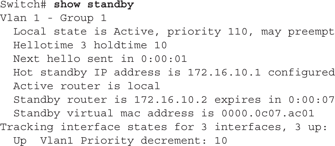
In the preceding output, you can see that the active routing device is 172.16.10.1 and the standby RP is 172.16.10.2.
For a shorter description, add the brief parameter to the preceding command:
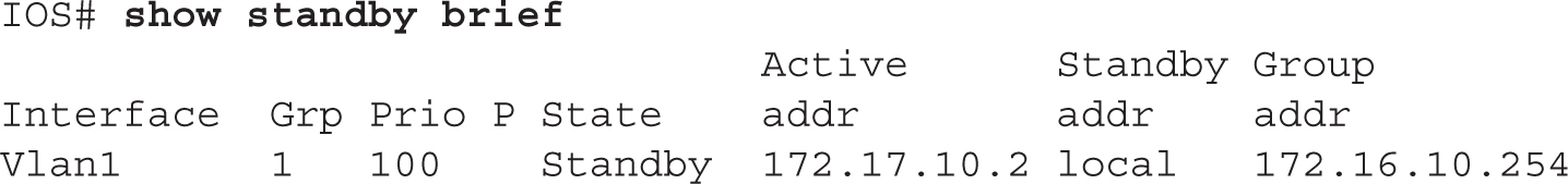
In this example, this router, for VLAN 1, is in a standby state and the virtual IP address for the standby group is 172.16.10.254.
For additional troubleshooting, you can use the debug standby command from Privileged EXEC mode. This command displays all HSRP messages that have been sent and received by the RP.
9.09. The digital resources that accompany this book contain a multimedia demonstration of configuring and verifying HSRP on a router.
Other Protocols
This section will introduce two other protocols that you can use instead of HSRP:
![]() Virtual Router Redundancy Protocol (VRRP)
Virtual Router Redundancy Protocol (VRRP)
![]() Gateway Load Balancing Protocol (GLBP)
Gateway Load Balancing Protocol (GLBP)
Virtual Router Redundancy Protocol
Virtual Router Redundancy Protocol (VRRP) performs a similar function as Cisco’s proprietary HSRP. The one major downside to HSRP is that it is a proprietary protocol. VRRP, however, is an open standard and is defined in IETF’s RFC 2338. Like HSRP, VRRP has end stations that use a virtual router for a default gateway. VRRP is supported for Ethernet media types, as well as in VLANs and MPLS VPNs.
HSRP and VRRP are very similar and accomplish the same goal: default gateway redundancy. HSRP is proprietary to Cisco, and VRRP is an open standard.
VRRP and HSRP are very similar protocols. One main difference between the two is that HSRP uses a virtual IP address for the default gateway, whereas VRRP can use either a virtual IP address or the interface address of the master router. If a virtual IP address is used, an election process takes place to choose a master router. The router with the highest priority is chosen as the master. All other routers are backup routers. If a real IP address is used, the router that has that address assigned to its interface must be the master router.
VRRP object tracking ensures that the best VRRP router is selected as the master of the group based on priority and interface tracking.
VRRP is an IP protocol and has an IP protocol number of 112. The VRRP master router is responsible for generating VRRP multicast messages. It sends these messages to a multicast address of 224.0.0.18. The master typically generates these messages every second. If the master VRRP router fails, a backup VRRP router seamlessly processes the traffic sent to the master router’s IP address. This process is referred to as object tracking: object tracking ensures that the best VRRP router is selected as the master of the group based on priority and interface tracking. VRRP supports preemption so that a failed master, after it has been repaired, can resume its role as master.
Note: The configuration of VRRP is beyond the scope of this book.
Gateway Load Balancing Protocol
The Gateway Load Balancing Protocol (GLBP) is a Cisco-proprietary protocol, like HSRP. One of the limitations of HSRP and VRRP is that only one router in the HSRP group is active and can forward traffic for the group—the rest of the routers sit idle. This is not an efficient process where one or more routing devices are not processing any traffic, nor are you taking advantage of the bandwidth of the connections that these other routing devices are connected to.
Cisco designed GLBP to rectify this issue. GLBP allows the dynamic assignment of a group of virtual addresses to end stations. With GLBP, up to four routing devices in the group can participate in the forwarding of traffic. Plus, if a GLBP routing device fails, fault detection occurs automatically and another GLBP routing device picks up the forwarding of packets for the failed routing device.
Here are some of the benefits of GLBP:
![]() Like HSRP, GLBP supports clear-text and MD5 password authentication between GLBP routing devices.
Like HSRP, GLBP supports clear-text and MD5 password authentication between GLBP routing devices.
![]() GLBP supports up to 1024 virtual routers on a routing device.
GLBP supports up to 1024 virtual routers on a routing device.
![]() GLBP can load-balance traffic via four forwarding routing devices in a subnet or VLAN.
GLBP can load-balance traffic via four forwarding routing devices in a subnet or VLAN.
Be familiar with the benefits of GLBP.
GLBP Operation In GLBP, there are two types of routers: Active Virtual Gateway (AVG) and Active Virtual Forwarder (AVF). The AVG is the master gateway device and is responsible for assigning virtual MAC addresses to end stations when the end stations perform an ARP for the GLBP default gateway address. Basically, the AVG is responsible for address management in the GLBP group.
The AVG is responsible for processing the ARP request for the virtual IP address(es).
An AVF is a routing device that forwards traffic for a GLBP group. The AVG is also an AVF. Basically, up to four routing devices configured in the same GLBP group are AVFs.
I’ll use Figure 9-6 to give a basic illustration of how GLBP works. In this example, RP-A is the master (AVG). When PC-A sends an ARP request for the default gateway MAC address, the AVG is responsible for responding back with a virtual MAC address to the end station. In this example, it responded back with its own virtual MAC address. PC-B then ARPs for the same gateway address. RP-A responds back with a virtual MAC address. Based on the load-balancing algorithm used by GLBP, RP-A responds back with a different virtual MAC address (RP-B’s). Load balancing is discussed in the next section. As you can see from this example, both RP-A and RP-B are forwarding traffic for the same VLAN.

GLBP also supports interface tracking. With interface tracking, if a tracked interface on an AVF fails, the AVF demotes itself and has another AVF pick up the processing associated with this failed interface. This process is similar to HSRP’s interface tracking feature.
An active virtual gateway (AVG) will reply with up to four possible virtual MAC addresses of the active virtual forwarders (AVFs) for the subnet/VLAN.
Load Balancing with GLBP Multiple RPs can be used to forward traffic with GLBP to perform load balancing. GLBP supports three methods of load balancing:
![]() Round-robin
Round-robin
![]() Weighted
Weighted
![]() Host-dependent
Host-dependent
The default method of load balancing is round-robin. With round-robin load balancing, the AVG assigns a different AVF default gateway address to each client. If you have two routing devices and six clients, three clients will use the AVG and three will use the AVF.
With weighted load balancing, a weighting factor is used to determine which AVF’s address the AVG routing device assigns to an end station. This enables you to tune GLBP so that a certain amount of hosts use one routing device rather than another if there is a difference in processing power between the routing devices.
With host-based load balancing, a host is assigned the same virtual gateway address each time. However, if the routing device associated with this address fails, another routing device within GLBP can pick up the processing so that redundancy is provided.
Note: The configuration of GLBP is beyond the scope of this book.
CERTIFICATION SUMMARY
Two types of routing protocols can be used to define or learn destination networks: static and dynamic. To create a static route, use the ip route command. For a default route, use 0.0.0.0/0 as the network number and subnet mask. To view your router’s routing table, use the show ip route command. You must first execute the ipv6 unicast-routing command to enable IPv6. An address must be assigned to each interface, typically using the EUI-64 method, for it to process IPv6 packets.
When setting up IP routing, you must enable the routing protocol and configure IP routing on your router’s interfaces. The router command takes you into the routing process, while the network command specifies what interfaces will participate in the routing process. Use the ip address command to assign IP addresses to your router’s interfaces.
RIPv1 generates local broadcasts every 30 seconds to share routing information, with a hold-down period of 180 seconds. Hop count is used as the metric for choosing paths. RIP can load-balance across six equal-cost paths to a single destination. RIPv2 uses multicasts instead of broadcasts and also supports VLSM for hierarchical routing and route summarization. RIPv2, to speed up convergence, uses triggered updates. Use the router rip command to go into the routing process and use the network command to specify your connected networks. When specifying your connected networks, specify only the Class A, B, or C network number (not subnet numbers), since RIPv1 is classful: even though RIPv2 is classless, configure it as a classful protocol. Use the version command to enable RIPv2. The debug ip rip command will display the actual routing contents that your router advertises in its updates or receives in neighbors’ updates.
The show ip protocols command displays information about the IP routing protocols currently configured and running on your router. It shows metric information, administrative distances, neighboring routers, and routes that are being advertised. The show ip route command displays the IP routing information currently being used by your router. An R in the left-hand column indicates an RIP route.
HSRP is a Cisco-proprietary protocol that provides default gateway redundancy and is invisible to the end stations in the VLAN. A single virtual IP and MAC address is used per group. An active routing device, elected by the routing device with the highest priority (or IP address, if a tie occurs), forwards traffic. A standby routing device monitors the active routing device. There are six stages an HSRP might go through: initial, learning, listening, speaking, standby, and active. A routing device goes into a speaking state when an election occurs, or if it is the active or standby routing device. The active routing device can tell the rest of the routing devices about the virtual addresses. To enable HSRP, use the standby ip command on a routing device’s interface. HSRP supports both preemption and interface tracking.
VRRP is an open standard for default gateway redundancy. VRRP has a master and backup routing devices. Either a virtual IP address or a real IP address (of the master) is used.
GLBP is an enhanced version of HSRP. It allows for up to four routing devices to forward traffic from the group. Routing devices are grouped together, and each group is assigned one or more virtual addresses. The AVG is responsible for address management, whereas the AVFs forward traffic—the AVG can also be an AVF. GLBP supports three types of load balancing: round-robin (default), weighted, and host-dependent.
 TWO-MINUTE DRILL
Static Routes
![]() Use the
Use the ip route command to configure a static route.
![]() After the subnet mask parameter, you have two ways of specifying how to reach the destination network: you can tell the router either the next-hop neighbor’s IP address or the interface the router should exit to reach the destination network. The former has an administrative distance of 1 and the latter, 0 (a directly connected route).
After the subnet mask parameter, you have two ways of specifying how to reach the destination network: you can tell the router either the next-hop neighbor’s IP address or the interface the router should exit to reach the destination network. The former has an administrative distance of 1 and the latter, 0 (a directly connected route).
![]() The
The ipv6 unicast-routing command globally enables IPv6 and must be the first IPv6 command executed on the router. The ipv6 address command assigns the prefix, the length, and the use of EUI-64 to assign the interface ID.
Dynamic Routing Protocol Basics
![]() To set up IP on your router, you need to enable the routing protocol and assign IP addresses to your router’s interfaces.
To set up IP on your router, you need to enable the routing protocol and assign IP addresses to your router’s interfaces.
![]() Use the
Use the router and network commands to enable routing. With classful protocols, use the class address in the network command.
RIP
![]() RIP uses hop count as a metric and has a hop-count limit of 15. IP RIP supports up to six equal-cost paths to a single destination.
RIP uses hop count as a metric and has a hop-count limit of 15. IP RIP supports up to six equal-cost paths to a single destination.
![]() RIPv1 sends out periodic routing updates as broadcasts every 30 seconds. The hold-down timer is 180 seconds. It is a classful protocol.
RIPv1 sends out periodic routing updates as broadcasts every 30 seconds. The hold-down timer is 180 seconds. It is a classful protocol.
![]() RIPv2 uses triggered updates and sends its updates out as multicasts. It is a classless protocol and supports VLSM and route summarization. Optionally, RIPv2 updates can be authenticated.
RIPv2 uses triggered updates and sends its updates out as multicasts. It is a classless protocol and supports VLSM and route summarization. Optionally, RIPv2 updates can be authenticated.
![]() Use the
Use the router rip and network commands to set up RIP. Use the version command to hard-code the version. Use the following commands for troubleshooting: show ip protocols, show ip route, and debug ip rip.
![]() After making a change to an IP routing protocol, use the
After making a change to an IP routing protocol, use the clear ip route * command to clear the IP routing table and rebuild it.
![]() To enable HSRP, use the
To enable HSRP, use the standby ip command on a routing device’s interface.
![]() HSRP is proprietary, and VRRP is an open standard. Both accomplish the same thing: default gateway redundancy within a VLAN.
HSRP is proprietary, and VRRP is an open standard. Both accomplish the same thing: default gateway redundancy within a VLAN.
![]() HSRP uses a virtual address as the default gateway address; VRRP supports the use of a physical or virtual address.
HSRP uses a virtual address as the default gateway address; VRRP supports the use of a physical or virtual address.
![]() GLBP, which is proprietary to Cisco and based on HSRP, allows more than one active routing device in a subnet.
GLBP, which is proprietary to Cisco and based on HSRP, allows more than one active routing device in a subnet.
SELF TEST
The following Self Test questions will help you measure your understanding of the material presented in this chapter. Read all the choices carefully, as there may be more than one correct answer. Choose all correct answers for each question.
Static Routes
1. Enter the command to set up a static route to 192.168.1.0/24, where the next-hop address is 192.168.2.2: __________.
2. What subnet mask would you use to set up a default route?
A. 0.0.0.0
B. 255.255.255.255
C. Depends on the type of network number
D. None of these answers
3. What is the default administrative distance of a static route where the next hop specified is the IP address of a neighboring router?
A. 0
B. 1
C. 90
D. 120
4. Which IPv6 command must first be entered on a Cisco router?
A. router ipv6-unicast
B. ipv6 address
C. ipv6 unicast-routing
D. ipv6 support enable
Dynamic Routing Protocol Basics
5. You have a distance vector protocol such as RIP. You’ve entered the RIP process by executing router rip. On one of your router’s interfaces, you have the following IP address: 192.168.1.65 255.255.255.192. Enter the command to include this interface in the RIP routing process: __________.
RIP
6. RIP generates routing updates every __________ seconds.
A. 15
B. 30
D. 90
7. RIP has a hold-down period of __________ seconds.
A. 60
B. 120
C. 180
D. 280
8. RIP has a maximum hop count of __________ hops.
A. 10
B. 15
C. 16
D. 100
9. RIP supports load balancing for up to __________ __________ paths.
A. Six, unequal-cost
B. Four, unequal-cost
C. Four, equal-cost
D. Six, equal-cost
10. Which of the following is true concerning RIPv2?
A. It uses triggered updates.
B. It uses broadcasts.
C. It is classful.
D. It doesn’t support route summarization.
11. Enter the router command used to view which routing protocols are active on your router, as well as their characteristics and configuration: __________.
Default Gateway Redundancy
12. Which of the following is a valid virtual MAC address for an HSRP group?
A. 0000.6e00.0014
B. 0000.0c07.ac18
C. 0000.ac07.0c0a
D. 0000.0cac.0c0f
SELF TEST ANSWERS
Static Routes
1. ![]()
ip route 192.168.1.0 255.255.255.0 192.168.2.2
2. ![]() A. A default route is set up with an IP address and mask of 0.0.0.0 0.0.0.0.
A. A default route is set up with an IP address and mask of 0.0.0.0 0.0.0.0.
![]() B is incorrect because this number indicates that the complete IP address is a network number, commonly called a host route. C is incorrect because the network number would use a standard subnet mask based on the network you’re trying to reach: 0.0.0.0 as a subnet mask indicates all hosts. And since there is a correct answer, D is incorrect.
B is incorrect because this number indicates that the complete IP address is a network number, commonly called a host route. C is incorrect because the network number would use a standard subnet mask based on the network you’re trying to reach: 0.0.0.0 as a subnet mask indicates all hosts. And since there is a correct answer, D is incorrect.
3. ![]() B. The default administrative distance of a static route pointing to a neighbor’s IP address is 1.
B. The default administrative distance of a static route pointing to a neighbor’s IP address is 1.
![]() A is incorrect because 0 is the value of a static route with an interface or a connected route. C is incorrect because 90 is EIGRP’s administrative distance, and D, 120, is RIP’s administrative distance.
A is incorrect because 0 is the value of a static route with an interface or a connected route. C is incorrect because 90 is EIGRP’s administrative distance, and D, 120, is RIP’s administrative distance.
4. ![]() C. The
C. The ipv6 unicast-routing command globally enables IPv6 and must be the first IPv6 command executed on the router.
![]() A and D are invalid commands. B assigns an IPv6 address to an interface.
A and D are invalid commands. B assigns an IPv6 address to an interface.
Dynamic Routing Protocol Basics
5. ![]()
network 192.168.1.0. Remember that RIPv1 is classful.
RIP
6. ![]() B. RIP generates routing updates every 30 seconds.
B. RIP generates routing updates every 30 seconds.
![]() A, C, and D are invalid update intervals.
A, C, and D are invalid update intervals.
7. ![]() C. RIP has a hold-down period of 180 seconds.
C. RIP has a hold-down period of 180 seconds.
![]() A, B, and D are invalid hold-down periods.
A, B, and D are invalid hold-down periods.
8. ![]() B. RIP has a maximum hop count of 15 hops.
B. RIP has a maximum hop count of 15 hops.
![]() A, C, and D are invalid maximum hop-count values.
A, C, and D are invalid maximum hop-count values.
9. ![]() D. RIP supports load balancing for up to six equal-cost paths.
D. RIP supports load balancing for up to six equal-cost paths.
![]() A and B are invalid because RIP doesn’t support unequal-cost paths. C is incorrect because four is the default, but six is the maximum.
A and B are invalid because RIP doesn’t support unequal-cost paths. C is incorrect because four is the default, but six is the maximum.
10. ![]() A. RIPv2 supports triggered updates.
A. RIPv2 supports triggered updates.
![]() B is incorrect because RIPv2 uses multicasts. C is incorrect because RIPv2 is classless. D is incorrect because RIPv2 supports VLSM and route summarization.
B is incorrect because RIPv2 uses multicasts. C is incorrect because RIPv2 is classless. D is incorrect because RIPv2 supports VLSM and route summarization.
11. ![]() To view the IP routing protocols running on your router, use
To view the IP routing protocols running on your router, use show ip protocols.
Default Gateway Redundancy
12. ![]() B. HSRP virtual MAC addresses begin with 0000.0c07.ac.
B. HSRP virtual MAC addresses begin with 0000.0c07.ac.
![]() A, C, and D are incorrect because the MAC addresses don’t begin with 0000.0c07.ac.
A, C, and D are incorrect because the MAC addresses don’t begin with 0000.0c07.ac.