
6
Initial Router Configuration
CERTIFICATION OBJECTIVES
6.01 Router Hardware Components
6.03 Disabling Unused Services
This chapter builds upon the configuration concepts on the CCENT exam, covering some of the basic commands that you can use to access and configure a Cisco IOS router, which are, as you will see, much like those on the Catalyst IOS switches. The advantage this provides is that you don’t have to learn a complete new command-line interface (CLI). The chapter first covers the components of the router and its bootup process, including the use of the System Configuration Dialog script: this prompts you for information about how you want to configure your router. You’ll also learn about a new feature introduced in version 12.3T code, called AutoSecure. Finally, the chapter covers the commands used to create a very basic configuration on your IOS router, including setting up an interface for trunking.
CERTIFICATION OBJECTIVE 6.01
Router Hardware Components
Each IOS device has two main components: hardware and software. Almost every IOS-based router uses the same hardware and firmware components to assist during the bootup process, including the following: ROM (read-only memory), RAM (random access memory), flash, NVRAM (nonvolatile RAM), a configuration register, and physical lines and interfaces. All of these components can affect how the router boots up and finds and loads the operating system and its configuration file. The following sections cover these components in more depth.
Read-Only Memory (ROM)
The software in ROM cannot be changed unless you actually swap out the ROM chip on your router. ROM is nonvolatile—when you turn off your device, the contents of ROM are not erased. ROM contains the firmware necessary to boot up your router and typically has the following four components:
![]() POST (power-on self test) Performs tests on the router’s hardware components.
POST (power-on self test) Performs tests on the router’s hardware components.
![]() Bootstrap program Brings the router up and determines how the IOS image and configuration files will be found and loaded.
Bootstrap program Brings the router up and determines how the IOS image and configuration files will be found and loaded.
![]() ROM Monitor (ROMMON mode) A mini–operating system that allows you to perform low-level testing and troubleshooting; for instance, ROMMON is used during the password recovery procedure. To abort the router’s normal bootup procedure of loading IOS, use the CTRL-BREAK control sequence to enter ROMMON mode. The prompt in ROMMON mode is either > or
ROM Monitor (ROMMON mode) A mini–operating system that allows you to perform low-level testing and troubleshooting; for instance, ROMMON is used during the password recovery procedure. To abort the router’s normal bootup procedure of loading IOS, use the CTRL-BREAK control sequence to enter ROMMON mode. The prompt in ROMMON mode is either > or rommon>, depending on the router model.

POST performs self-tests on the hardware. The bootstrap program brings the router up and finds an IOS image. ROMMON contains a mini–operating system used for low-level testing and debugging. The Mini-IOS is a stripped-down version of IOS used for emergency booting of a router and is referred to as RXBOOT mode. All of these components are stored in ROM.
Other Components
Your router contains other components that are used during the bootup process, including RAM, flash, NVRAM, the configuration register, and the physical lines and interfaces. The following paragraphs explain these components.
RAM is like the memory in your PC. On a router, RAM (in most cases) contains the running IOS image, the active configuration file, any tables (including routing, ARP, and other tables), and internal buffers for temporarily storing information such as interface input and output buffers and logging messages. IOS is responsible for managing memory. When you turn off your router, everything in RAM is erased.
Flash is a form of nonvolatile memory, like ROM, meaning that when you turn the router off, the information stored in flash is not lost. Routers store their IOS image in flash, but other information can also be stored here, such as a secondary configuration file. Note that some lower-end Cisco routers actually run IOS directly from flash (not RAM). Flash is slower than RAM, a fact that can create performance issues.
NVRAM is like flash in that its contents are not erased when you turn off your router. It is slightly different, though, in that it uses a battery to maintain the information when the Cisco device is turned off. Routers (and switches) use NVRAM to store their configuration files.
The configuration register is a special register in the router that determines many of its bootup and running options, including how the router finds the IOS image and its configuration file. The configuration uses a part of memory space in NVRAM. As you will see later in this chapter, you can manipulate this register to affect how your router boots up. You can also use the boot command to influence the location from which IOS and configuration file are loaded (discussed in the “Bootstrap Program” section later).
Every router has at least one line and one physical interface. Lines, or ports, are typically used for management access; the console and auxiliary lines are examples. Interfaces are used to move traffic through the router; they can include media types such as Ethernet, Fast Ethernet (FE), Gigabit Ethernet (GE), serial, and others. These interfaces can be used during the bootup process—you can have the bootstrap program load IOS from a remote Trivial File Transfer Protocol (TFTP) server (instead of flash), assuming that you have a sufficient IP configuration on your router.
Flash is used to store the operating system, and NVRAM is used to store the configuration file. The configuration register is used to determine how the router will boot up.
CERTIFICATION OBJECTIVE 6.02
Router Bootup Process
A router typically goes through six steps when booting up:
1. The router loads and runs POST (located in ROM), testing its hardware components, including memory and interfaces.
2. The bootstrap program is loaded and executed.
3. The configuration register is checked to determine how to boot up (where to find the IOS image and configuration file).
4. The bootstrap program finds and loads an IOS image: Possible locations of IOS images include flash or a TFTP server.
5. Once IOS is loaded, IOS attempts to find and load a configuration file, which is normally stored in NVRAM—if IOS cannot find a configuration file, it starts up the System Configuration Dialog.
6. After the configuration is loaded, you are presented with the CLI (remember that the first mode you are placed into is User EXEC mode).
Once POST completes and the bootstrap program is loaded, the configuration is checked to determine what to do next.
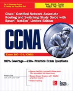
If you are connected to the console line, you’ll see the following output as your router boots up:


6.01. The digital resources that accompany this book contain a multimedia demonstration of booting up a Cisco router.
You should notice a few things about this output. First, notice that the router is loading the bootstrap program—System Bootstrap, Version 11.0(10c)—and then the IOS image—IOS (tm) 2500 Software (C2500-I-L), Version 12.0(5). During the bootup process, you cannot see the actual POST process (unlike Catalyst switches). However, you will see information about the interfaces going up and/or down—this is where IOS is loading the configuration and bringing up those interfaces that you previously activated. Sometimes, if the router has a lot of interfaces, the Press RETURN to get started! message is mixed in with the interface messages. Once the display stops, just press ENTER to access User EXEC mode. This completes the bootup process of the router.
When a router boots up, it runs POST, loads the bootstrap program, finds and loads IOS, and loads its configuration file—in that order.
Bootstrap Program
As you saw in the bootup code example, the bootstrap program went out and found the IOS and loaded it. The bootstrap program goes through the following steps when trying to locate and load the IOS image:
1. Examine the configuration register value. This value is a set of four hexadecimal digits. The last digit affects the bootup process. If the last digit is between 0x2 and 0xF, then the router proceeds to the next step. Otherwise, the router uses the values shown in Table 6-1 to determine how it should proceed.
2. Examine the configuration file in NVRAM for boot system commands, which tell the bootstrap program where to find IOS. These commands are shown in the following paragraph.
3. If no boot system commands are found in the configuration file in NVRAM, use the first valid IOS image found in flash.
4. If there are no valid IOS images in flash, generate a TFTP local broadcast to locate a TFTP server (this is called a netboot and is not recommended because it is very slow and not very reliable for large IOS images).
5. If no TFTP server is found, load the Mini-IOS in ROM (RXBOOT mode).
6. If there is a Mini-IOS in ROM, then the Mini-IOS is loaded and you are taken into RXBOOT mode; otherwise, the router either retries finding an IOS image or loads ROMMON and goes into ROM Monitor mode.
TABLE 6-1 Fourth Hex Character Configuration Register Values

Table 6-1 contains the three common configuration register values in the fourth hex character of the configuration register that are used to influence the bootup process. The values in the configuration register are represented in hexadecimal, the register being 16 bits long.
The configuration register is used to influence how IOS boots up. Remember the values in Table 6-1.
For step 2 of the bootup process, here are the boot system commands that you can use to influence the order that the bootstrap program should use when trying to locate the IOS image:

6.02. The digital resources that accompany this book contain a multimedia demonstration of using boot system commands on a router.

The order in which you enter the boot system commands is important, since the bootstrap program processes them in the order in which you configure them—once the program finds an IOS image, it does not process any more boot system commands in the configuration file. These commands are also supported on Catalyst IOS switches.
The boot system flash command tells the bootstrap program to load the specified IOS filename in flash when booting up. Note that, by default, the bootstrap program loads the first valid IOS image in flash. This command tells the bootstrap program to load an image that’s different from the first one. This might be necessary if you perform an upgrade and you have two IOS images in flash—the old one and the new one. By default, the old one still loads first (because it appears first in flash) unless you override this behavior with the boot system flash command or delete the old IOS flash image. You can also have the bootstrap program load IOS from a TFTP server—this is not recommended for large images, since the image is downloaded via the User Datagram Protocol (UDP), which is slow. And last, you can tell the bootstrap program to load the Mini-IOS in ROM with the boot system rom command. To remove any of these commands, just preface them with the no parameter.
The boot system commands can be used to modify the default behavior of where the bootstrap program should load IOS. When the bootstrap program loads, it examines the configuration file stored in NVRAM for boot system commands. If they are found, the bootstrap program uses these commands to find IOS. If no boot system commands are found, the router uses the default behavior in finding and loading the IOS image (first image in flash, a broadcast to a TFTP server, and then IOS in ROM, if it exists). When the router is booting and you see the message boot: cannot open “flash:”;, this indicates you misconfigured a boot system command and the corresponding IOS image filename in flash doesn’t exist.
System Configuration Dialog
When a router boots up, runs its hardware diagnostics, and loads IOS software, IOS then attempts to find a configuration file in NVRAM. If it can’t find a configuration file to load, IOS then runs the System Configuration Dialog, commonly referred to as Setup mode, which is a script that prompts you for configuration information. The purpose of this script is to ask you questions that will allow you to set up a basic configuration on your router: It is not intended as a full-functioning configuration tool. In other words, the script doesn’t have the ability to perform all the router’s configuration tasks. Instead, it is used by novices who are not that comfortable with the IOS CLI. Once you become familiar with the CLI and many of the commands on the router, you’ll probably never use this script again.
If no startup configuration can be found in NVRAM, then the System Configuration Dialog script starts.
Running the System Configuration Dialog
As mentioned in the previous paragraph, one way to access the System Configuration Dialog is to boot up a router without a configuration in NVRAM. The second way is to use the setup Privileged EXEC mode command, shown here:


Information included in brackets ([]) indicates the default value—if you press ENTER, the value in the brackets is used. One problem with the script is that if you make a mistake, you can’t go back to the preceding question. Instead, you must use the CTRL-C break sequence to abort the script and start over. The following sections break down the different components of the script.
The questions that the script asks you might differ from router to router, depending on the hardware model, the interfaces installed in it, and the software running on it.
Status and Global Configuration Information
At the beginning of the script, you are asked whether or not you want to continue. If you answer yes or y, the script will continue; otherwise, if you answer no or n, the script is aborted and you are returned to Privileged EXEC mode. The second thing that you are asked is if you want to see the status of the router’s interfaces. If you answer yes, you’ll see all of the interfaces on the router, the interfaces’ IP addresses, and the status of the interfaces.
After the status information, you are taken into the actual configuration. The first part of the configuration deals with all configuration information for the router except for the interfaces, which is the second part. In this part of the configuration, you are asked for things like the Privileged EXEC password, VTY password (telnet and SSH), which network protocols you want to activate globally, and other global configuration information.
Note that you are prompted for two Privileged EXEC passwords in the script: enable secret and enable password. Even though you would normally configure only one, the script requires you to enter both and also requires that both passwords be different.
Protocol and Interface Configuration Information
After configuring the global information for the router, you are then led through questions about which interfaces you want to use and how they should be configured. The script is smart enough to ask only configuration questions based on how you answered the global questions. As an example, if you activate IP, the script asks you for each activated interface, if you want the interface to process IP, and, if yes, the IP addressing information for the interface.
Exiting Setup Mode
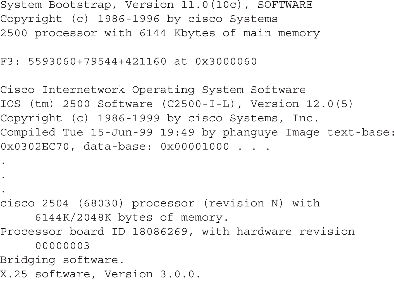
After you answer all of the script’s configuration questions, you are shown the router configuration the script created using your answers to the script’s questions. Note that IOS hasn’t yet activated the configuration file. Examine the configuration closely and then make one of the three choices shown in Table 6-2. Also, if you enter 1 as your option, when the script starts over again, the information that you previously entered appears in brackets and will be the default values when you press the ENTER key on an empty line.
TABLE 6-2 Options at the End of the System Configuration Dialog
6.03. The digital resources that accompany this book contain a multimedia demonstration of using the System Configuration Dialog on a Cisco router.
Remember that the System Configuration Dialog script is started when the router boots up and there is no configuration in NVRAM, or you use the setup command from Privileged EXEC mode. Also, know the three options at the end of the Setup dialog script. You can press CTRL-C to abort the script.
Configuration Register
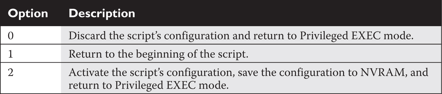
As mentioned in the preceding section, the configuration register is used by the bootstrap program to determine the location from which the IOS image and configuration file should be loaded. Once the router is booted up, you can view the configuration register value with the show version command:
You need to go to the very bottom of the display in order to view the register value.
You can see the system image the router used upon bootup in the show version command. If you misconfigured the boot system commands or are using TFTP for the download, the router might not be able to find and load an IOS image.
Changing the Configuration Register from Configuration Mode
You can change the configuration register value from Configuration mode or from ROMMON mode. If you already have Privileged EXEC access to the router and want to change the register value, use this command:

If you configured your router, rebooted it, and it came up with the System Configuration Dialog prompt, then you either forgot to save your running configuration before rebooting or misconfigured the configuration register.
The register value is four hexadecimal digits, or 16 bits, in length. Each bit position in the register, though, indicates a function that the bootstrap program should take. Therefore, you should be very careful when configuring this value on your router.
Many sites on the Internet have downloadable configuration register utility programs for Cisco routers. Boson has a free one at this location: www.boson.com/FreeUtilities.html. With Boson’s utility, you can select or deselect specific boot options, which will automatically generate the correct register value for you.
When entering the register value, you must always precede it with 0x, indicating that this is a hexadecimal value. If you don’t do so, the router assumes the value is decimal and converts it to hexadecimal. On Cisco routers, the default configuration register value is 0x2102, which causes the router to use the default bootup process in finding and locating IOS images and configuration files. If you change this to 0x2142, this tells the bootstrap program that, upon the next reboot, it should locate IOS using the default behavior, but not to load the configuration file in NVRAM; instead, you are taken directly into the System Configuration Dialog. This is the value that you will use to perform the password recovery procedure.
The default configuration register value is 0x2102, which causes a router to boot up using its default bootup process (look for boot system commands in the startup configuration, and if none are found, load the first IOS in flash, then load the default startup configuration file). You can see the configuration register value with the show version command. If you’ve changed this value, you will see the existing value and the value the router will use upon rebooting. If the router boots up and doesn’t have a configuration, but one exists in NVRAM, check the router’s configuration register to see if it is set to 0x2142: this register setting causes IOS to ignore any configuration file in NVRAM when booting.
Changing the Configuration Register from ROM Monitor
Of course, one problem with the Configuration mode method of changing the register value is that you must gain access to Privileged EXEC mode first. This can be a problem if you don’t know the passwords on the router. A second method, though, allows you to change the register value without having to log into the router. To use this method, you’ll need console access to the router—you can’t do this from the auxiliary line or from a VTY session. Next, you’ll turn off the router and then turn it back on. As the router starts booting, you’ll break into ROMMON mode with the router’s break sequence. To break into the router, once you see the bootstrap program has loaded, you can, in most cases, use the CTRL-BREAK control sequence to break into ROMMON mode. Note that this control sequence may differ, depending on the terminal emulation program you are using on your PC.
Once in ROMMON mode, you can begin the process of changing the register value using one of two methods, depending on the router model that you have. Some of Cisco’s routers, such as the 1900, 1800, and 2600 series, use the confreg command. This script asks you basic questions about the function and bootup process of the router. What’s nice about the script is that you don’t need to know the hexadecimal values for the configuration register, since the router will create them for you as you answer these questions. Here is an example of using this script:
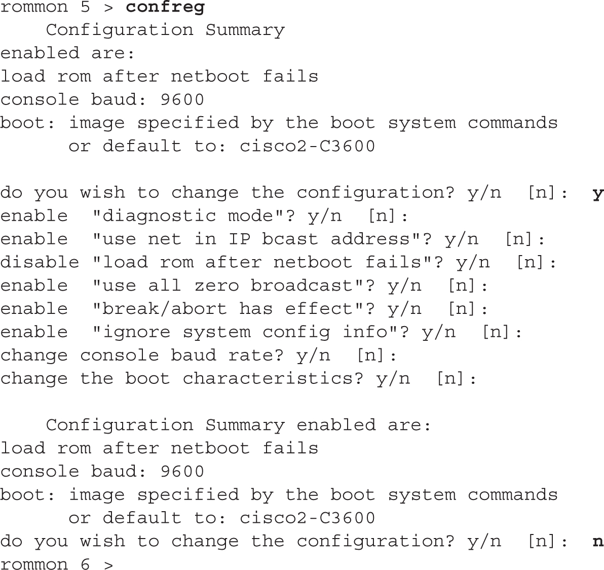
6.04. The digital resources that accompany this book contain a multimedia demonstration of changing the configuration register in ROMMON mode (confreg) and using the IOS CLI config-register command on a router.
As a shortcut, you could also execute the following command from ROMMON mode: confreg 0x2142.
Just as in the System Configuration Dialog, any information in brackets ([]) represents default values. The first question that it asks is if you want to “change the configuration,” which means change the register: answer y to continue. If you answer y to ignore system config info, the third hexadecimal digit becomes 4, making a router’s register value appear as 0x2142. This option is used when you want to perform the password recovery procedure. The next-to-last question is change the boot characteristics?—this question, if you answer y, will repeat the questions again. Answer n to exit the script. If you make any changes, you are asked to save them (do you wish to change the configuration?)—answer y to save your new register value. Once you are done changing the register, reboot the router. On many routers, just type in the letter i or b in ROMMON mode to boot it up.
When performing the password recovery procedure, break into ROMMON mode and change the configuration register value to 0x2142 and boot up the router. Once booted up, the router will ignore the configuration in NVRAM and take you into the System Configuration Dialog. Using CTRL-C will break you out of this utility and take you to User EXEC mode. Enter Privileged EXEC mode and restore your configuration with the copy startup-config running-config command. The no shutdown command is not listed in the router’s NVRAM configuration, so you will have to enable the interfaces manually. This is also true if you copy and paste a configuration into a router with its interfaces disabled, such as a newly booted router.
CERTIFICATION OBJECTIVE 6.03
Disabling Unused Services
The next two sections, “Manually Disabling Unused Services” and “AutoSecure” introduce some basic security for Cisco routers: disabling unnecessary services that may be running on your IOS router. Some services on Cisco devices might not be needed and therefore can be disabled. This increases security and reduces overhead on the Cisco device. The first subsection introduces how to disable services manually, which applies to both Cisco switches and Cisco routers, while the second subsection discusses how to run a script, called AutoSecure, to accomplish basically the same thing, although this is supported only on IOS routers.
Manually Disabling Unused Services
A quick way of seeing which TCP/IP ports are open on an IOS device is by using this command:
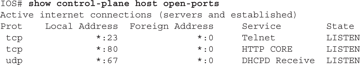
Many services, whether they be TCP/IP or some other management service, might have been originally configured on the device but now either are no longer necessary, go against company policy, or present a security risk. These services should be removed from the IOS device’s operation. One option of doing that is manually disabling the services. The following two sections discuss how to do this for global and interface services.
Global Commands
Here is a list of commands you might want to execute to disable unnecessary global processes or enable necessary global processes:


You should disable the following processes/programs on your IOS device (these are global configurations):
![]() IP source routing Similar to Token Ring’s source routing, where the source determines the path to reach a destination in IP.
IP source routing Similar to Token Ring’s source routing, where the source determines the path to reach a destination in IP.
![]() Finger Used to garner information about accounts on a machine. Finger is enabled by default on IOS routers. The
Finger Used to garner information about accounts on a machine. Finger is enabled by default on IOS routers. The no service finger command has been replaced by the no ip finger command.
![]() Small servers These are programs with port numbers less than 20, like Chargen, that can be used by hackers to hack into your router or create a DoS attack (in IOS 12.0 and later, these are disabled by default). For example, if the echo service is enabled, an attacker could send a fake DNS query with the source address of the DNS server and a destination of the router; when the router receives this, it responds back to the DNS server, which might allow the attacker to bypass any internal filters that would normally drop a UDP DNS query.
Small servers These are programs with port numbers less than 20, like Chargen, that can be used by hackers to hack into your router or create a DoS attack (in IOS 12.0 and later, these are disabled by default). For example, if the echo service is enabled, an attacker could send a fake DNS query with the source address of the DNS server and a destination of the router; when the router receives this, it responds back to the DNS server, which might allow the attacker to bypass any internal filters that would normally drop a UDP DNS query.
![]() CDP Proprietary Cisco protocol that is used to share basic hardware and software information with a connected Cisco device—this is enabled by default across all interfaces on an IOS device (discussed in Chapter 16).
CDP Proprietary Cisco protocol that is used to share basic hardware and software information with a connected Cisco device—this is enabled by default across all interfaces on an IOS device (discussed in Chapter 16).
![]() BootP Can be used by Cisco routers to acquire IOS images on BootP servers—this is enabled by default.
BootP Can be used by Cisco routers to acquire IOS images on BootP servers—this is enabled by default.
![]() Configuration auto-loading The
Configuration auto-loading The no service config command disables the router from finding its configuration on a TFTP server; no boot network prevents the router from loading an IOS image from a TFTP server.
![]() DNS lookups Enabled by default and are sent to the 255.255.255.255 address. To globally disable DNS lookups, use the
DNS lookups Enabled by default and are sent to the 255.255.255.255 address. To globally disable DNS lookups, use the no ip domain-lookup command; manually define DNS servers with the ip name-server command.
![]() TCP keepalives Should be enabled to verify if a session is still open and to prevent “orphaned” sessions. Sessions that are no longer in existence will be removed by the router.
TCP keepalives Should be enabled to verify if a session is still open and to prevent “orphaned” sessions. Sessions that are no longer in existence will be removed by the router.
![]() DHCP Disable the DHCP server function of the router unless it’s the only device that can supply IP addressing information to hosts (typically for branch offices). DHCP is discussed in Chapters 8.
DHCP Disable the DHCP server function of the router unless it’s the only device that can supply IP addressing information to hosts (typically for branch offices). DHCP is discussed in Chapters 8.
![]() HTTP server Routers can be managed via a web browser—disable this on a perimeter router and use HTTPS instead.
HTTP server Routers can be managed via a web browser—disable this on a perimeter router and use HTTPS instead.
![]() Nagle Handles TCP congestion by allowing multiple characters to be sent in the same segment, instead of different segments, like telnet.
Nagle Handles TCP congestion by allowing multiple characters to be sent in the same segment, instead of different segments, like telnet.
![]() FTP server Disable the FTP server and FTP upload functionality on the router (the router should not be an FTP server).
FTP server Disable the FTP server and FTP upload functionality on the router (the router should not be an FTP server).
![]() TFTP server Disable TFTP server functions on the router (the router should not be a TFTP server).
TFTP server Disable TFTP server functions on the router (the router should not be a TFTP server).
![]() IdentD server Disable the identification server on the router.
IdentD server Disable the identification server on the router.
![]() X.25 PAD This is enabled by default on most Cisco routers and should be disabled if you are not using X.25.
X.25 PAD This is enabled by default on most Cisco routers and should be disabled if you are not using X.25.
![]() Password recovery procedure Disable the ability to perform the password recovery procedure from ROMMON mode.
Password recovery procedure Disable the ability to perform the password recovery procedure from ROMMON mode.
Some of these commands are deprecated in the latest IOS versions, and some are specific to an IOS package.
Interface Commands
Here is a list of commands you might want to execute to disable unnecessary layer 3 interface processes, such as router interfaces, by default, or VLAN switch interfaces:

You should disable the following processes/programs on your IOS device (these are interface configurations):
![]() Proxy ARP Used by routers to reply to a local ARP request for a remote device (in a different subnet).
Proxy ARP Used by routers to reply to a local ARP request for a remote device (in a different subnet).
![]() ICMP redirects Your router tells the source about an alternative path.
ICMP redirects Your router tells the source about an alternative path.
![]() ICMP unreachables Your router tells the source that the destination is unreachable—disable this, because you don’t want hackers knowing if a device is not reachable, or just not there.
ICMP unreachables Your router tells the source that the destination is unreachable—disable this, because you don’t want hackers knowing if a device is not reachable, or just not there.
![]() ICMP mask replies Your router tells a querier what the subnet mask is (disabled by default).
ICMP mask replies Your router tells a querier what the subnet mask is (disabled by default).
![]() Route caching You want to force all traffic to go through ACLs and security instead of using an ASIC’s cache (this should be used with caution, since you could overburden the device’s CPU).
Route caching You want to force all traffic to go through ACLs and security instead of using an ASIC’s cache (this should be used with caution, since you could overburden the device’s CPU).
![]() MOP (Maintenance and Operation Protocol) Performs a similar function to TFTP in DecNET environments.
MOP (Maintenance and Operation Protocol) Performs a similar function to TFTP in DecNET environments.
![]() CDP Proprietary Cisco protocol that is used to share basic hardware and software information with a connected Cisco device. Disable this on interfaces where you have non-Cisco devices or nontrusted devices.
CDP Proprietary Cisco protocol that is used to share basic hardware and software information with a connected Cisco device. Disable this on interfaces where you have non-Cisco devices or nontrusted devices.
![]() NTP If an interface is not expecting to receive NTP messages, disable NTP on that interface. If you are implementing NTP, make sure you’re using NTP with authentication (discussed in Chapter 17).
NTP If an interface is not expecting to receive NTP messages, disable NTP on that interface. If you are implementing NTP, make sure you’re using NTP with authentication (discussed in Chapter 17).
![]() Directed broadcasts As of 12.0 and later, directed broadcasts are disabled by default.
Directed broadcasts As of 12.0 and later, directed broadcasts are disabled by default.
![]() Gratuitous ARPs Most routers send out ARPs whenever a client connects and negotiates IP addressing information over a PPP link; a hacker can use this to execute an ARP poison attack, filling up the local ARP table.
Gratuitous ARPs Most routers send out ARPs whenever a client connects and negotiates IP addressing information over a PPP link; a hacker can use this to execute an ARP poison attack, filling up the local ARP table.
![]() Interfaces IOS switches, by default, have all interfaces enabled. Cisco recommends disabling interfaces that are not in use.
Interfaces IOS switches, by default, have all interfaces enabled. Cisco recommends disabling interfaces that are not in use.
AutoSecure
The problem with manually disabling unused services is that you have to manually configure individual commands. AutoSecure is an IOS feature originally introduced on the ISR series of Cisco routers, such as the 870s, 1800s, 2800s, and 3800s, that allows you to put a basic security configuration on your router by running a simple script. It was introduced in IOS 12.3 and 12.3T. It is a Privileged EXEC script similar to the System Configuration Dialog: where the latter creates a basic configuration for a router, AutoSecure focuses only on security functions for securing a router. Like the setup script, AutoSecure asks you basic questions about securing your router. It will automatically enable or disable specific services running on your router; set up a stateful firewall by configuring Context-Based Access Control (CBAC), which requires a security IOS image; configure access control lists; and perform other tasks.
To run the AutoSecure script, from Privileged EXEC mode, execute the auto secure command:
![]()
You can run AutoSecure in two modes:
![]() Interactive You are prompted for security information during the scripting process.
Interactive You are prompted for security information during the scripting process.
![]() Noninteractive IOS performs all security functions based on a set of defaults from Cisco.
Noninteractive IOS performs all security functions based on a set of defaults from Cisco.
AutoSecure basically secures the router at two levels:
![]() Management plane (traffic destined to the router)
Management plane (traffic destined to the router)
![]() Forwarding plane (traffic going through the router)
Forwarding plane (traffic going through the router)
With no extra parameters with the auto secure command, the router will secure both the management and forwarding planes while asking you questions about the security process.
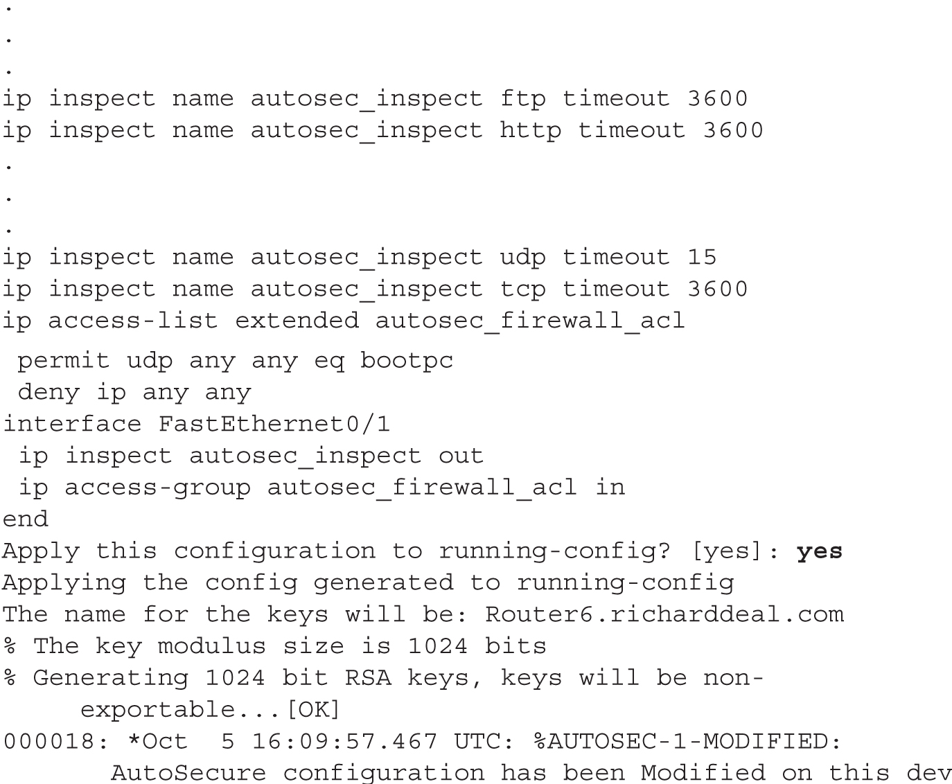
Here is an example of running the AutoSecure script:


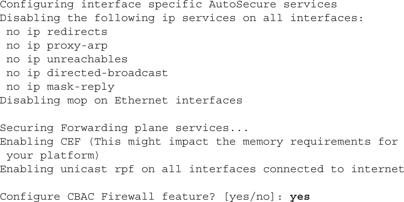


During any of the prompts, you can type ? to bring up help, or press CTRL-C to abort the script. At the beginning of the script, you are asked if the router is connected to the Internet. If so, tell AutoSecure which interface (or interfaces) is connected to the Internet so that it can set up its security policies correctly. In the preceding example, Fast Ethernet0/1 is connected to the Internet.
6.05. The digital resources that accompany this book contain a multimedia demonstration of running AutoSecure.
At this point, global services for the Management plane are enabled or disabled. In this section, you are asked to create a login banner, where an example is provided. To start the banner, enter a delimiting character that won’t show up in the text, such as ^ or #. When you type in this character the second time, this will end the banner. Authentication, authorization, and accounting (AAA) and SSH are then configured. Following this, AutoSecure disables certain services under all of the router’s interfaces.
At this point, AutoSecure will enable Cisco Express Forwarding (CEF), enable Context-Based Access Control (CBAC), and create an ACL to block unwanted IP traffic. This finishes the script, and AutoSecure displays the configuration it will activate on the router. Press the ENTER key or enter yes to accept and activate the configuration.
Cisco recommends running the AutoSecure script after you run the System Configuration Dialog, but before you begin any other advanced configuration tasks from the CLI. If you don’t run the System Configuration Dialog, put a basic configuration on your router, such as configuring and enabling the interfaces and configuring a routing protocol, and then run AutoSecure.
Router Configuration
This chapter builds upon the basic IOS configuration commands covered in your CCENT studies, where you learned how to move around the CLI, change the name of the device, configure passwords, configure hardware characteristics for an interface, and enable an interface. This section discusses these fundamentals in addition to router-specific commands to use for a basic configuration.
Interface Configuration
This section on router configuration covers additional interface configurations, such as configuring assigning an IP address to an interface and changing the bandwidth metric. Following sections will discuss some show commands to verify your interface’s configuration.
IP Addressing Information
You can use many commands on the router to set up your IP addressing information. One of the most commonly used commands is the command to assign an IP address to an interface; however, many more commands are used, including those for setting up DNS, restricting directed broadcasts, and performing other tasks. The following sections cover some of these configurations.
Unlike layer 2 switches (such as the 2960), which need only a single IP address for remote management, routers need a unique IP address on each interface that will route IP traffic. Actually, each interface on a router is a separate network or subnet, and therefore you need to plan your IP addressing appropriately and assign a network number to each router segment and then take an unused host address from the segment and configure it on the interface of the router. This address then becomes the default gateway for devices connected to that interface.
Let’s look at a couple of examples of incorrectly and correctly assigning IP addresses to a router’s interfaces. Figure 6-1 shows an invalid configuration example. In this example, only one network number is used: 192.168.1.0/24. Notice that each interface on the router has an address from this same network number. Actually, if you would try to configure this addressing scheme on a router, you would get an overlapping address error and be prevented from completing the addressing configuration.
FIGURE 6-1 Invalid addressing configuration for a router

Each interface needs a unique host address, as shown in Figure 6-2. Notice that in this example, each interface has an address from a different network number when compared to the other interfaces on the router. Which host address you choose for the router interface is up to personal preference. Many administrators use either the first or last host address in the network number for the router’s interface, but any valid, unused host address from that network number can be used.
FIGURE 6-2 Correct addressing configuration for a router

As you have probably already guessed, configuring an IP address on a router requires that you be in Interface Subconfiguration mode. Here is the syntax of this command:

This syntax, as you can see, is the same as that used for configuring an IP address on the 2960 switch (but under the VLAN interface). You can verify your IP addressing configuration with the show interfaces or show ip interfaces command, discussed later in this section.
6.06. The digital resources that accompany this book contain a multimedia demonstration of configuring an IP address on an interface of a Cisco router.
Using the example in Figure 6-2, the following would be the router’s IP addressing configuration:

If you omit the IP address on a router’s interface, it will not process any IP traffic on that interface. If you misconfigured an IP address on a router’s interface, use the no ip address command to remove it. Optionally, you can use the ip address command with the correct IP address and subnet mask to overwrite the existing IP address configuration on the interface. Also, you cannot have two different router interfaces with IP addresses in the subnet. For example, you cannot have an IP address of 192.168.1.1/24 on E0 and an IP address of 192.168.1.2/24 on E1—you’ll receive an error message on the console when trying to configure the second address. Remember how to configure IP addressing on a router, since this might be part of a configuration or troubleshooting simulation question.
Bandwidth Parameter
All interfaces have a bandwidth value assigned to them. This is used by certain routing protocols, such as Open Shortest Path First (OSPF) and Enhanced Interior Gateway Routing Protocol (EIGRP), when making routing decisions. (Routing protocols are covered in Chapters 14, 18, 19, and 20.) For LAN-based interfaces, the speed of the interface becomes the bandwidth value, where the bandwidth is measured in kilobits per second (Kbps). However, on synchronous serial interfaces, the bandwidth defaults to 1554 Kbps, or the speed of a T1 link. This is true no matter what the physical clock rate is on the interface (you can change the serial link’s clocked rate with the clock rate command). To change the bandwidth value for an interface, use the bandwidth Interface Subconfiguration mode command:

As an example, a serial interface clocked at 56,000 bps should have its bandwidth value changed to 56 Kbps, like this:
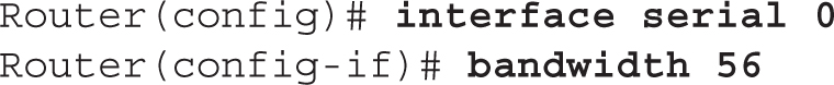
Note that the bandwidth command does not change the clock rate on an interface: the clock rate command does this. The bandwidth command affects only routing protocols that use bandwidth as a metric.
The show ip interface Command
Common verification commands that you will use on a router are the show interfaces (discussed in Chapter 1) and show ip interface commands. The latter command displays the IP configuration of your router’s interfaces, including its IP address and subnet mask:
![]()
Here is an abbreviated output of the show ip interface command:

As you can see from this command, the status of the interface is shown, the IP address and mask are displayed, and direct broadcasts will be dropped if received on the interface. Any access list applied to the interface is also displayed.
Use the show ip interface command to determine whether an ACL is applied to an interface.
An additional parameter to the preceding command, brief, will display a single-line description for each interface, as shown here:

6.07. The digital resources that accompany this book contain a multimedia demonstration of using the show ip interface command.
This is an extremely useful command when you want to see a quick overview of all of the interfaces on the router, their IP addresses, and their statuses. This command also works on switches.
Use the show ip interface brief command to see a quick overview of the IP addresses on interfaces and their operational state.
Subnet Zero Configuration
Starting with IOS 12.0, Cisco automatically allows you to use IP subnet zero networks—the first network number in a subnetted network. Prior to IOS 12.0, you were not, by default, allowed to use these subnets. However, if you needed extra networks, you could enable their use by configuring the ip subnet-zero command:
![]()
In IOS 12.0 and later, this command will already be in the router’s default configuration.
Static Host Configuration
As you are well aware, in the IP world, we typically don’t type in an IP address to reach a destination. For example, if you want to reach Cisco’s site, in your web browser address bar, you type www.cisco.com or http://www.cisco.com. Your web browser then resolves the host and domain names to an IP address. The router also supports hostnames for certain operations, such as ping and telnet (discussed in Chapter 7).
You can have your router resolve hostnames to IP addresses in two ways: static and dynamic (using DNS). You can create a static resolution table using this command:

You must first specify the name of the remote host. Optionally, you can specify a port number for the host—this defaults to 23 for telnet if you omit it. After this, you can list up to eight IP addresses for this host. The router will try to reach the host with the first address, and if that fails, it will try the second address, and so on. Use the show hosts command to examine your static entries, which are discussed following the next section.
DNS Resolution Configuration
If you have access to a DNS server or servers, you can have your router use these to resolve names to IP addresses. This is configured with the ip name-server command:

You can list up to six DNS servers for the router to use with this command. Use the show hosts command to examine your static and dynamic entries. This command is discussed in the next section.
Many administrators don’t like using DNS to resolve names to addresses on routers because of one nuisance feature on the router: Whenever you type a nonexistent command on the router, the router assumes you are trying to telnet to a device by that name and tries to resolve it to an IP address. This is annoying because either you have to wait for the DNS query to time out or you must execute the break sequence (CTRL-SHIFT-6).
One of the first things I typically configure on a router is the no ip domain-lookup command so that when I mistype commands, I don’t have to wait for the router to attempt to resolve the mistyped command to an IP address.
You have another option, though, and that is to disable DNS lookups on the router with the following command:
![]()
6.08. The digital resources that accompany this book contain a multimedia demonstration of using and disabling name resolution on a Cisco router.
The show hosts Command
To view the static and dynamic DNS entries in your router’s resolution table, use this command:
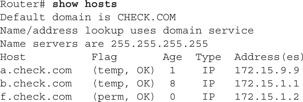
The first two entries in the table were learned via a DNS server (temp flag), whereas the last entry was configured statically on the router with the ip host command (perm flag).
Using IOS Features

The last few sections have covered how you configure basic IP addressing features on your Cisco router. You can perform the following exercises on a Cisco router to reinforce these skills. Use the router simulator included with the book, or you can use a real Cisco router. You can find a picture of the network diagram for the simulator in the Introduction to this book.
Access the simulator and click the Lab Instructions tab. Click the McGraw-Hill Education tab (to the right of the Standard and Custom tabs) at the top left. Double-click Exercise 6-1. This will load a basic configuration on devices in the network topology, including IP addresses on the Host PCs based on the simple configuration commands you learned during your CCENT studies.
1. Access the 2600-1 router. Click the Lab Instructions tab and use the drop-down selector and choose 2600-1; or click the NetMap tab and double-click the 2600-1 device icon.
2. Configure an IP address of 192.168.1.1/24 on fastethernet0/0 of the 2600-1 router and bring the interface up. Go to Privileged EXEC mode and type these commands: configure terminal, interface fastethernet0/0, ip address 192.168.1.1 255.255.255.0, no shutdown, and exit.
3. Configure an IP address of 192.168.2.1/24 on the serial0 interface, set the clock rate to 64,000 bps, and enable the interface.
4. Configure serial0: interface serial0, ip address 192.168.2.1 255.255.255.0, clock rate 64000, no shutdown, and exit. Return to Privileged EXEC mode by typing end.
5. Save the configuration file on the router: copy running-config startup-config.
6. Test connectivity between the Host-1 PC and the 2600-1. Use the drop-down selector for Devices and select Host-1. Test the connection from Host-1 by pinging the 2600-1: ping 192.168.1.1. The ping should be successful.
7. Access the 2600-2 router: Click the Lab Instructions tab and use the drop-down selector and choose 2600-2; or click the NetMap tab and double-click the 2600-2 device icon.
8. Configure an IP address of 192.168.3.1/24 on fastethernet0/0 of the 2600-2 router and bring up the interface. Go to Privileged EXEC mode and type these commands: configure terminal, interface fastethernet0/0, ip address 192.168.3.1 255.255.255.0, no shutdown, and exit.
9. Configure an IP address of 192.168.2.2/24 on the serial0 interface and enable the interface. Configure serial0: interface serial0, ip address 192.168.2.2 255.255.255.0, no shutdown, and exit. Return to Privileged EXEC mode by typing end.
10. Save the configuration file on the router: copy running-config startup-config.
11. Test connectivity between the 2600-2 and 2600-1 routers: ping 192.168.2.1. The ping should be successful.
12. Test connectivity between the Host-3 PC and the 2600-2. Click the Lab Instructions tab and use the drop-down selector and choose Host-3; or click the NetMap tab and double-click the Host-3 device icon.. Test the connection from Host-3 by pinging the 2600-2: ping 192.168.3.1. The ping should be successful.
You should now be more familiar with configuring IP addressing information on a router.
Router-on-a-Stick
Typically, we think of routing as traffic coming in one physical interface and leaving another physical interface. As you learned in Chapter 2, however, trunks can be used to support multiple VLANs, where each VLAN has a unique layer 3 network or subnet number. Certain router models and interface combinations, such as the 1800 series, support trunk connections. A router-on-a-stick is a router that has a single trunk connection to a switch and routes between the VLANs on this trunk connection. You could easily do this without a trunk (access-link connections), but each VLAN would require a separate access-link (physical) interface on the router, and this would increase the price of the router solution.
For instance, if you had five VLANs, and your router didn’t support trunking, you would need five physical LAN interfaces on your router in order to route between the five VLANs. However, with a trunk connection, you can route between all five VLANs on a single interface. Because of cost and scalability, most administrators prefer using a router-on-a-stick approach to solve their routing problems in switched networks.
A router-on-a-stick is a router that has a single trunk connection to a switch and routes between multiple VLANs on this trunk. Subinterfaces are used on the router to designate the VLAN with which they are associated. Each VLAN needs a different IP subnet configuration.
Subinterface Configuration
To set up a router-on-a-stick, you need to break up your router’s physical interface into multiple logical interfaces, called subinterfaces. Cisco supports up to 1000 interfaces on a router, which includes both physical and logical interfaces. Once you create a subinterface, a router will treat this logical interface just like a physical interface: you can assign layer 3 addressing to it, enable, it, disable it, and do many other things.
To create a subinterface, use the following command:

After entering the physical interface type and port identifier, follow this with a dot (.) and a subinterface number. The subinterface number can range from 0 to 4,294,967,295. The number that you use for the subinterface number is only for reference purposes within IOS, and the only requirement is that when creating a subinterface, you use a unique subinterface number. Many administrators prefer to use the VLAN number that the subinterface will handle for the subinterface number; however, this is not a requirement, and the two numbers are not related in any way.
At the end of the statement, you must specify the type of connection if the interface is of type serial; otherwise, you can omit it. The point parameter is used for point-to-point serial connections, and multipoint is used for multipoint connections (many devices connected to the interface). The multipoint parameter is used for connections that have more than one device connected to them (physically or logically). For a router-on-a-stick configuration, you can omit the connection type, since the default is multipoint for LAN interfaces.
Interface Encapsulation
Once you create a subinterface, you’ll notice that your CLI prompt has changed and that you are now in Subinterface Configuration mode. If you are routing between VLANs, you’ll need an interface that supports trunking. Some things are configured on the major interface, and some things are configured on the subinterface. Configurations such as duplexing and speed are done on the major (or physical) interface. Most other tasks are done on the subinterface (the logical interface), including to which VLAN the subinterface belongs and its IP addressing information.
6.09. The digital resources that accompany this book contain a multimedia demonstration of setting up a router-on-a-stick.
When setting up your subinterface for a router-on-a-stick, one thing that you must configure is the type of trunking—ISL or 802.1Q—and the VLAN with which the subinterface is associated, like this:

Use the encapsulation command to specify the trunk type and the VLAN associated with the subinterface. The VLAN number you specify here must correspond to the correct VLAN number in your switched network. You must also set up a trunk connection on the switch for the port to which the router is connected. Once you do this, the switch will send tagged frames to the router, and the router, using your encapsulation, will understand how to read the tags. The router will be able to see from which VLAN the frame came and match it up with the appropriate subinterface that will process it. Remember that only a few of Cisco’s switches today support ISL: all of them support 802.1Q, which is denoted with the dot1q parameter.
Be familiar with how to create a subinterface with the interface command. The router and switch must be using the same VLAN encapsulation type: 802.1Q or ISL. Also remember to configure the switchport as a trunk with the switchport mode trunk command. The switch and router must use the same encapsulation, 802.1Q being the most common.
Router-on-a-Stick Example Configuration
Let’s look at an example to see how a router-on-a-stick is configured. Figure 6-3 shows this configuration. Assume that this is a 3800 router, that the Fast Ethernet interface is the first interface in the first slot, and that the switch is using 802.1Q trunking on the connected interface.
FIGURE 6-3 Router-on-a-stick example

Here’s the code example for this router:
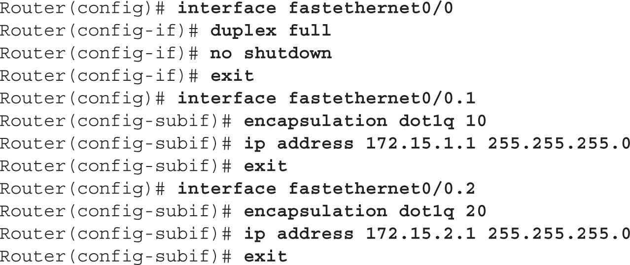
Notice in this example that the subinterface numbers in the interface command (1 and 2) do not match the VLAN numbers in the encapsulation command (10 and 20); remember that the subinterface numbers are used by IOS only to reference the particular subinterface and do not have to match any configuration on the subinterface.
If you are configuring static routes and want to route traffic out of a particular subinterface, specify the major interface along with the subinterface number, such as fastethernet0/0.2. Static routes are discussed in Chapter 9.
CERTIFICATION SUMMARY
The router contains the following components in ROM: POST, bootstrap program, and ROM Monitor (ROMMON). POST performs hardware tests. The bootstrap program finds and loads IOS. ROMMON provides basic access to the router to perform testing and troubleshooting.
The configuration register affects how the router boots up. By default, POST is run, the bootstrap program is loaded, the IOS image is located, and the configuration file is executed. You can change this by using boot system commands or by changing the configuration register value. The show version command displays the current register value and what it will be upon a reload. The default register value is typically 0x2102. For the password recovery, use 0x2142.
The router needs an IP address on each interface where it will be processing IP traffic. This is configured on an interface with the ip address command. Use the show ip interface brief command to view the status and configuration of your interfaces.
A router-on-a-stick uses a single trunk connection from a router to a switch to route among multiple VLANs. You must create a subinterface on your router for each VLAN. Each subinterface requires the encapsulation isl|dot1q command and a layer 3 address or addresses.
 TWO-MINUTE DRILL
Router Hardware Components
![]() ROM stores the Mini-IOS, the bootstrap program, ROMMON, and POST.
ROM stores the Mini-IOS, the bootstrap program, ROMMON, and POST.
![]() Flash stores IOS images.
Flash stores IOS images.
![]() NVRAM stores the configuration files.
NVRAM stores the configuration files.
![]() RAM stores the active configuration, including tables and buffers.
RAM stores the active configuration, including tables and buffers.
Router Bootup Process
![]() The configuration register and
The configuration register and boot system commands can be used to override the default router bootup behavior.
![]() Use the
Use the show version command to see the IOS version being used by the router as well as the register value.
![]() If the fourth hexadecimal character of the configuration register is 0x0, the router boots into ROMMON mode; if 0x1, the router boots the Mini-IOS or the first file in flash if a Mini-IOS doesn’t exist; if 0x2–0xF, the router uses the default boot sequence. The default configuration register value is 0x2102. For the password recovery, it’s 0x2142. Use the
If the fourth hexadecimal character of the configuration register is 0x0, the router boots into ROMMON mode; if 0x1, the router boots the Mini-IOS or the first file in flash if a Mini-IOS doesn’t exist; if 0x2–0xF, the router uses the default boot sequence. The default configuration register value is 0x2102. For the password recovery, it’s 0x2142. Use the config-register IOS command to change this value.
![]() Here is the default bootup process: The bootstrap program examines the configuration register to determine how to boot up. If it is the default, the bootstrap program looks for
Here is the default bootup process: The bootstrap program examines the configuration register to determine how to boot up. If it is the default, the bootstrap program looks for boot system commands in the configuration file in NVRAM. If none are found, it looks for IOS in flash. If no files are found in flash, the bootstrap program generates a TFTP local broadcast to locate IOS. If no TFTP server is found, the bootstrap program loads the Mini-IOS in ROM. If there is no Mini-IOS in ROM, the bootstrap program loads ROMMON.
![]() The System Configuration Dialog (setup script) will run when the router boots up and there is no configuration file in NVRAM.
The System Configuration Dialog (setup script) will run when the router boots up and there is no configuration file in NVRAM.
![]() Use the
Use the confreg command from ROMMON mode to change the configuration register to 0x2142 to perform the password recovery process.
![]() AutoSecure puts a basic security configuration on a router, such as passwords, CBAC, ACLs, SSH, and other information. It is run from Privileged EXEC mode using the
AutoSecure puts a basic security configuration on a router, such as passwords, CBAC, ACLs, SSH, and other information. It is run from Privileged EXEC mode using the auto secure command.
Router Configuration
![]() IP addresses are configured on each interface of the router that will process IP packets with the
IP addresses are configured on each interface of the router that will process IP packets with the ip address Interface Subconfiguration mode command. The bandwidth command changes the metric of the interface, which is used by some routing protocols.
![]() The
The show ip interface brief command displays a brief configuration and status of each interface on the router.
Router-on-a-Stick
![]() A router-on-a-stick is a router with a single trunk connection to a switch; a router routes between the VLANs on this trunk connection.
A router-on-a-stick is a router with a single trunk connection to a switch; a router routes between the VLANs on this trunk connection.
![]() To route between VLANs with a router-on-a-stick, use subinterfaces and specify the VLAN with the
To route between VLANs with a router-on-a-stick, use subinterfaces and specify the VLAN with the encapsulation isl|dot1q command on the subinterface.
SELF TEST
The following Self Test questions will help you measure your understanding of the material presented in this chapter. Read all the choices carefully, as there may be more than one correct answer. Choose all correct answers for each question.
Router Hardware Components
1. Which of the following are stored in ROM? (Choose two answers.)
A. POST
B. ROMMON
C. Configuration file
D. System recovery file
2. Which type of memory does not maintain its contents during a power-off state?
A. NVRAM
B. ROM
C. RAM
D. Flash
Router Bootup Process
3. Which router command would you use to view the configuration register value?
A. show register
B. show interfaces
C. show configuration
D. show version
4. Enter the router IOS Configuration mode command to change the configuration register so that it will not load the startup configuration file located in NVRAM: __________.
AutoSecure
5. When is AutoSecure run on a router?
A. Manually from Privileged EXEC mode
B. Manually from Configuration mode
C. Automatically when the router boots up without a configuration
D. Automatically when the router boots up without a configuration or manually from Privileged EXEC mode
6. You need to configure an IP address on a router’s serial interface (s0/0). Use the last host address in 192.168.1.128/30. The interface is a DCE, and you need to enable the interface. The speed of the connection is 64 Kbps. Set the bandwidth metric to match the speed of the interface. Enter the commands to accomplish this.
7. Enter the router Global Configuration mode command that will allow you to use the first address in the first subnet of a subnetted C class network: __________.
8. Examine this output:

Enter the router command that created this output: __________.
Router-on-a-Stick
9. When configuring a router-on-a-stick, the configuration is done on __________.
A. physical interfaces
B. major interfaces
C. subinterfaces
10. Which router-on-a-stick command defines the VLAN for the interface?
A. vlan
B. encapsulation
C. trunk
D. frame-type
SELF TEST ANSWERS
Router Hardware Components
1. ![]() A and B. POST, ROMMON, the Mini-IOS, and the bootstrap program are in ROM.
A and B. POST, ROMMON, the Mini-IOS, and the bootstrap program are in ROM.
![]() C is incorrect because the configuration file is stored in NVRAM, and D is a nonexistent file.
C is incorrect because the configuration file is stored in NVRAM, and D is a nonexistent file.
2. ![]() C. RAM contents are erased when you turn off the device.
C. RAM contents are erased when you turn off the device.
![]() A, B, and D are incorrect; NVRAM, ROM, and flash maintain their contents when the device is turned off.
A, B, and D are incorrect; NVRAM, ROM, and flash maintain their contents when the device is turned off.
Router Bootup Process
3. ![]() D. Use the
D. Use the show version command to view the configuration register value.
![]() A is a nonexistent command. B is incorrect because
A is a nonexistent command. B is incorrect because show interfaces shows only interface statistics. C is the old command version for show startup-config.
4. ![]() Enter the
Enter the config-register 0x2142 command in Configuration mode to cause the router to boot up and not load the configuration file in NVRAM.
AutoSecure
5. ![]() A. AutoSecure can be run manually only from Privileged EXEC mode with the
A. AutoSecure can be run manually only from Privileged EXEC mode with the auto secure command.
![]() B, C, and D are incorrect.
B, C, and D are incorrect.
Router Configuration
6. ![]() The router’s configuration will look like this:
The router’s configuration will look like this:

7. ![]() The
The ip subnet-zero command allows you to use the first and last subnet when configuring IP addresses on interfaces of your router.
8. ![]()
show ip interface brief
Router-on-a-Stick
9. ![]() C. Trunking with a router-on-a-stick is done on subinterfaces.
C. Trunking with a router-on-a-stick is done on subinterfaces.
![]() Hardware characteristics are configured on A (physical interfaces) when trunking, not VLANs. Sometimes the term in B (major interfaces) is used to refer to a physical interface.
Hardware characteristics are configured on A (physical interfaces) when trunking, not VLANs. Sometimes the term in B (major interfaces) is used to refer to a physical interface.
10. ![]() B. Use the
B. Use the encapsulation command to specify the trunking encapsulation and the VLAN number for the subinterface.