
Chapter 5. Introduction to Security Operations Management
This chapter covers the following topics:
![]() Introduction to identity and access management
Introduction to identity and access management
![]() Enterprise Mobility management
Enterprise Mobility management
![]() Asset management
Asset management
![]() Configuration and change management
Configuration and change management
Security operations management is a key task within information security. Security professionals need to understand the foundation of the various management activities performed to enable effective security controls.
“Do I Know This Already?” Quiz
The “Do I Know This Already?” quiz helps you determine your level of knowledge on this chapter’s topics before you begin. Table 5-1 details the major topics discussed in this chapter and their corresponding quiz sections. You can find the answers in Appendix A Answers to the “Do I Know This Already?” Quizzes and Q&A Questions.
1. In which phase of the identity and account lifecycle are the access rights assigned?
a. Registration
b. Access review
c. Privileges provisioning
d. Identity validation
2. What is an advantage of a system-generated password?
a. It is easy to remember.
b. It complies with the organization’s password policy.
c. It is very long.
d. It includes numbers and letters.
3. Which of the following is a password system that’s based on tokens and uses a challenge-response mechanism?
a. Synchronous token system
b. Asynchronous token system
c. One-time token system
d. Time-base token system
4. In the context of the X.500 standard, how is an entity uniquely identified within a directory information tree?
a. By its distinguish name (DN)
b. By its relative distinguish name (RDN)
c. By its FQDN
d. By its DNS name
5. What is the main advantage of single sign-on?
a. The user authenticates with SSO and is authorized to access resources on multiple systems.
b. The SSO server will automatically update the password on all systems.
c. The SSO server is a single point of failure.
d. SSO is an open source protocol.
6. What is the main advantage of an SIEM compared to a normal log collector?
a. It provides log storage.
b. It provides log correlation.
c. It provides a GUI.
d. It provides a log search functionality.
7. In asset management, what is used to create a list of assets owned by the organization?
a. Asset inventory
b. Asset acceptable use
c. Asset disposal
d. Asset category
8. Which of the following are advantages of a cloud-based mobile device manager compared to an on-premises model? (Select all that apply.)
a. Higher control
b. Flexibility
c. Scalability
d. Easier maintenance
9. Which of the following is a typical feature of a Mobile Device Management solution?
a. Device jailbreak
b. PIN lock enforcement
c. Call forwarding
d. Speed dial
10. In the context of configuration management, which of the following best defines a security baseline configuration?
a. A configuration that has been formally reviewed and approved
b. The default configuration from the device vendor
c. A configuration that can be changed without a formal approval
d. The initial server configuration
11. A change that is low risk and might not need to follow the full change management process is classified as which of the following?
a. Standard
b. Emergency
c. Normal
d. Controlled
12. In which type of penetration assessment is all information about the systems and network known?
a. White box approach
b. Black box approach
c. Gray box approach
d. Silver box approach
13. In which type of vulnerability disclosure approach is the vulnerability exploit not disclosed?
a. Partial disclosure
b. Full disclosure
c. Responsible disclosure
d. Initial disclosure
14. Which of the following are required before a patch can be applied? (Select all that apply.)
a. Formally start a request for change.
b. Perform a security assessment.
c. Verify that the patch works correctly.
d. Test the patch in the lab.
Foundation Topics
Introduction to Identity and Access Management
Identity and access management (IAM) has a very broad definition and in general includes all policies, processes, and technologies used to manage the identity, authentication, and authorization of an organization’s resources. Several disciplines and technologies are usually covered under the umbrella of IAM: access controls (which were described in detail in Chapter 4, “Introduction to Access Controls”), password management, the IAM lifecycle, directory management, and single sign-on (SSO), among others. This section provides an introduction to the main topics of IAM. Although IAM is not currently part of the SECFND blueprint, understanding the main topics of IAM is important for any security professional.
Phases of the Identity and Access Lifecycle
As discussed in Chapter 4, one of the properties of a secure identity is the secure issuance of that identity. Additionally, access privileges should be associated with an identity, and the identity’s validity and permissions should be constantly reviewed. At times, an identity and permissions should be revoked, and a process should be established to do this in a secure way. These processes are called identity proof and registration, account provisioning, access review, and access revocation. All of this goes under the umbrella of identity and account lifecycle management.
Figure 5-1 shows the four phases of the identity and access lifecycle, which are described in the list that follows:
![]() Registration and identity validation: A user provides information and registers for a digital identity. The issuer will verify the information and securely issue a unique and nondescriptive identity.
Registration and identity validation: A user provides information and registers for a digital identity. The issuer will verify the information and securely issue a unique and nondescriptive identity.
![]() Privileges provisioning: The resource owner authorizes the access rights to a specific account, and privileges are associated with it.
Privileges provisioning: The resource owner authorizes the access rights to a specific account, and privileges are associated with it.
![]() Access review: Access rights are constantly reviewed to avoid privilege creep.
Access review: Access rights are constantly reviewed to avoid privilege creep.
![]() Access revocation: Access to a given resource may be revoked due, for example, to account termination.
Access revocation: Access to a given resource may be revoked due, for example, to account termination.

Let’s review each of these phases in a bit more detail.
Registration and Identity Validation
The first step in a secure identity lifecycle is the user registration. During this phase, the user registers his data to request an identity. The second step of this process would be to verify the identity. This can be done in several ways, depending on the privileges associated with that identity. For example, starting the identity validation for a system administrator may require additional steps compared to a normal user. During this phase, a user could be asked to provide a copy of his identity card, HR could perform a background check, proof of a specific clearance level could be requested, and so on. Finally, the identity assigned will be unique and nondescriptive.
Privileges Provisioning
Once an identity has been assigned, privileges or access rights should be provisioned to that account. The privileges should be assigned by using the main security principles discussed in previous chapters of this book—that is, least privileges, separation of duty, and need to know. In general, privileges will be assigned in accordance with the organization’s security policy.
Depending on the access control model applied, the process might need to ensure that an authorization request is sent to the resource owner and that privileges are not assigned until the access has been approved. A temporal limit should also be applied to the privileges assigned.
For highly sensitive privileges, a more formal process might need to be established. For example, users may be asked to sign a specific nondisclosure agreement. Provisioning could also apply to existing accounts requesting access to additional resources, for example, due to a job change within the organization.
The registration, identity validation, and privileges provisioning phases are grouped together under the account provisioning step.
Access Review
Access rights and privileges associated with an account should be constantly reviewed to ensure that there is no violation to the organization’s security policy. The process should ensure a regular review of privileges as well as an event-driven review, such as when a user changes roles.
One of the issues in large organizations is the unneeded assignment of privileges, which brings up the privileges creep issue discussed in Chapter 4.
Access Revocation
When an employee changes jobs or leaves the organization, there may be a need to partially or completely revoke his associated access rights. A formal process should be established to make sure this is done properly. In some cases, privileges may need to be revoked before the actual event (for example, an involuntarily job termination) to ensure the employee does not cause damage to the organization before officially leaving.
Password Management
A password is a combination of characters and numbers that should be kept secret, and it is the most common implementation of the authentication-by-knowledge concept described in Chapter 4. Password authentication is usually considered one of the weakest authentication methods, yet it’s one of the most used due to its implementation simplicity.
The weakness of password authentication is mainly due to the human factor rather than technological issues. Here’s a list of some typical issues that lead to increased risk when using passwords as the sole authentication method:
![]() Users tend to use the same password across all systems and accounts.
Users tend to use the same password across all systems and accounts.
![]() Users tend to write down passwords (for example, on a sticky note).
Users tend to write down passwords (for example, on a sticky note).
![]() Users tend to use simple passwords (for example, their child’s name or 12345).
Users tend to use simple passwords (for example, their child’s name or 12345).
![]() Users tend to use the default system password given at system installation.
Users tend to use the default system password given at system installation.
Password management includes all processes, policies, and technologies that help an organization and its users to improve the security of their password-authentication systems. Password management includes policies and technologies around password creation, password storage, and password reset, as described in the sections that follow.
Password Creation
One of the most important steps in password management is creating a standard to define secure password requirements. This needs to be applied across the organization and for all systems. An organization should take into consideration the following requirements when building policies, processes, and standards around password creation:
![]() Strength: Establishing a policy about the password strength is very important to reduce the risk of users setting up weak passwords, which are easier to compromise via brute-force attacks, for example. Complexity and length requirements contribute to increasing the strength of a password. Complexity is usually enforced by asking the user to use a combination of characters, numbers, and symbols. Password length increases the difficulty of cracking a password. The shorter the password, the higher the risk. The strength and entropy of a password are the main factors used to measure the quality of a password. NIST SP 800-63 provides more information about password entropy and how passwords can be used in electronic authentication systems.
Strength: Establishing a policy about the password strength is very important to reduce the risk of users setting up weak passwords, which are easier to compromise via brute-force attacks, for example. Complexity and length requirements contribute to increasing the strength of a password. Complexity is usually enforced by asking the user to use a combination of characters, numbers, and symbols. Password length increases the difficulty of cracking a password. The shorter the password, the higher the risk. The strength and entropy of a password are the main factors used to measure the quality of a password. NIST SP 800-63 provides more information about password entropy and how passwords can be used in electronic authentication systems.
![]() Age: The age of a password (or better, the maximum age of a password) is an important attribute. Changing a password frequently is considered a best practice. The longer a password is used, the higher the risk of password compromise. The password requirement policy should dictate the maximum age of a password. Changing passwords frequently is better for security; however, it creates additional administrative overhead for users and systems.
Age: The age of a password (or better, the maximum age of a password) is an important attribute. Changing a password frequently is considered a best practice. The longer a password is used, the higher the risk of password compromise. The password requirement policy should dictate the maximum age of a password. Changing passwords frequently is better for security; however, it creates additional administrative overhead for users and systems.
![]() Reusability: Reusing the same password or part of it also increases the risk of password compromise. It is common practice to change just the last digit of a password or to use only two passwords repeatedly and just swap them when the time comes. Policy around reusability should ensure that passwords are not reused within a given amount of time.
Reusability: Reusing the same password or part of it also increases the risk of password compromise. It is common practice to change just the last digit of a password or to use only two passwords repeatedly and just swap them when the time comes. Policy around reusability should ensure that passwords are not reused within a given amount of time.
The policies around the creation of a password should also specify whether the password is created by the user or is automatically generated by the system. A hybrid approach would use both methods by combining a user-chosen password with a system-generated one. Table 5-2 summarizes the pros and cons of each of these methods.

Using passwords created by the users is the easiest method but is the riskiest from a security point of view. Users tend to use easy passwords, reuse the same passwords, and, in some cases, disclose password to others. Enforcing password requirements helps reduce the risk.
System-Generated Password
Using system-generated passwords is a stronger method than using user-created passwords because the password requirements are directly enforced. In most cases, the system can create the passwords by using a random password generator, which ensures higher entropy and is usually more difficult to compromise. The drawback of this method is that these types of passwords are more difficult to remember. Users, therefore, tend to write them down, which defeats the purpose of having a secure password.
One-Time Password and Token
A one-time password is a randomly generated password that can be used only once. One of the most used methods for implementing one-time password authentication is through a token device. The token device can be either a hardware device or implemented in software (soft-token), and it is basically a one-time password generator. For example, most of the authentication systems for online banking use token technologies.
A token device can work in two ways: synchronously and asynchronously. In most cases, the token generator is protected through a password or PIN. In synchronous token authentication, the token generator is synchronized with the authenticator server (for example, via time synchronization). When a user needs to authenticate, she will use the token to generate a one-time password that’s be used to authenticate to the system. In an asynchronous token system, the authenticator will produce a challenge. The user inputs the challenge in the token generator, which will use that information to generate the one-time password.
Password Storage and Transmission
Password management should ensure that policies and controls are in place to securely store passwords and that passwords are securely transmitted when used. Encrypting files that include passwords, storing hashes of the passwords instead of the passwords themselves, and implementing tight access controls on systems storing passwords are all methods that contribute to the secure storage of passwords. In addition, all external means of accessing passwords, such as a removable hard drive used to store passwords and even any documents that include passwords, should be appropriately secured.
Because passwords are used in the authentication process, they need to be transmitted over the network (for example, over the Internet). Policies should be in place to ensure passwords are protected while in transit. Network segmentation and encryption usually help with increasing the secure transmission of passwords. For example, HTTP can be used for normal website browsing, but HTTPS or an equivalent secure protocol should be required when performing authentication.
Password Reset
Password management should include policies and technologies to allow the resetting of passwords in a secure way. If an attacker is able to reset a password, all the rest of the things discussed so far are meaningless. Password reset is usually a task assigned to help desk personnel. In a large organization, with many users, accounts, and systems, the administration around resetting passwords can become cumbersome. Many organizations nowadays offer their employees and affiliates automatic ways to reset their passwords. This is usually done by requiring the user to provide an additional form of authentication (for example, by answering a security questionnaire) or token. Alternatively, a reset link can be sent to the user’s personal email address.
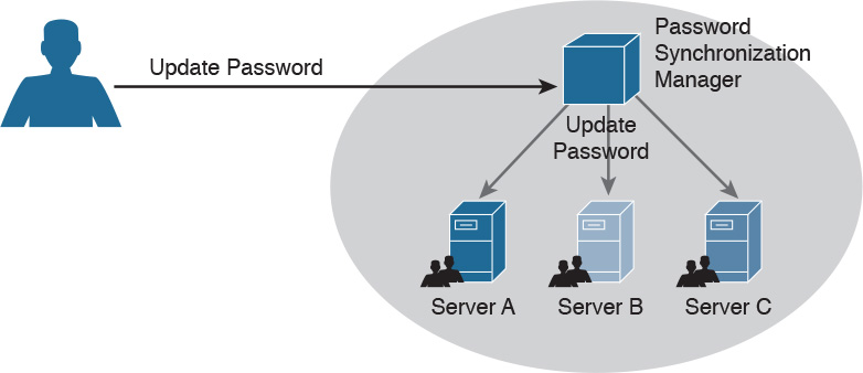
Password Synchronization
In large organizations, having to create an account on each system and for each user can be complicated both for the system administrator and the final user. For example, users might need to remember several passwords, depending on the systems they access, which in turn may foster the bad habit of writing down passwords on sticky notes. This can also cause increased calls to the help desk due to forgotten passwords. Additionally, when passwords need to be changed, due to a maximum-age password policy, for example, the user would need to change his password for each system.
Password synchronization technologies allow the user to set his password once, and then the management system will automatically push the password to all systems that are part of the synchronization process. This largely reduces the administration overhead around password management. The drawback of this method, however, is that once the password is compromised, the attacker is able to access all the systems. The organization should evaluate this risk as part of its security risk management.
Figure 5-2 shows an example of a password synchronization system. The user can change his password on the password synchronization manager, and the password will be updated on all the systems that are part of the synchronization domain.
Directory Management
Directories are repositories used by an organization to store information about users, systems, networks, and so on. Information stored in directories can be used for the purposes of identifying and authenticating users, as well applying security policies and authorization.
Using directory services for IAM offers a centralized place where all applications and processes can connect to get information about the organization’s resources. This reduces the overhead of having to replicate information across all systems. The disadvantage is that not all the systems are able to interface with directory services, and the directory server becomes a single point of failure for the IAM system. Replicated and distributed directory services may help overcoming these disadvantages.
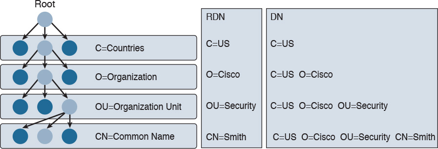
One of the most known implementations of directory services is the ITU-T X.500 series, which is a collection of standards that includes information on directory organization and the protocols to access the information within directories. In this implementation, the directory is organized in a hierarchical way. The data is represented in a directory information tree (DIT), and the information is stored in a directory information base (DIB).
Each entity is uniquely identified by its distinguish name (DN), which is obtained by attaching to the relative distinguish name (RDN) of the specific object the DN of the parent entity. Each entity contains several attributes. Here are some examples of attributes described in the X.500 schema:
![]() Country (C)
Country (C)
![]() Organization (O)
Organization (O)
![]() Organization unit (OU)
Organization unit (OU)
![]() Common name (CN)
Common name (CN)
![]() Location (L)
Location (L)
Figure 5-3 shows an example of a hypothetical DIT.

Figure 5-4 shows the difference between an RDN and a DN. For example, at the OU level, the RDN is OU=Security, whereas the DN includes all of the RDN up to the ROOT, so it is C=US, O=Cisco, OU=Security.
In the X.500 standards, the directory service agent (DSA) is the process that provides access to the information in the DIB and is where the directory user agent (DUA) component connects to request services. In a distributed directory environment, multiple DSAs exist that can interact with each other to provide services to the DUA.
The Directory Access Protocol (DAP) is used between a DUA and DSA to interrogate and modify the contents of the directories. Other protocols are part of the standard, such as the Directory System Protocol (DSP), which is used between two DSAs, the Directory Information Shadowing Protocol (DISP), and the Directory Operational Binding Management Protocol (DOP).
Figure 5-5 shows an example of interaction between a DUA and a DSA. The DUA uses DAP to query the directory. DISP is used between two DSAs.

If you think that this is too complex, you are not the only one. Due to the complexity of the X.500 directory, a lightweight version called the Lightweight Directory Access Protocol (LDAP) was created. As with X.500, in an LDAP system, directories and systems are organized hierarchically and use the same naming convention (that is, the distinguished name of an object is used to identify an object within the information tree).
In an LDAP system, the DUA is called the LDAP client, while the DSA is called the LDAP server. LDAP can coexist with and be used to query X.500-based systems.
Here are the key concepts related to directory management:
![]() Directories are repositories of information about an organization’s resources, including people, hardware, and software.
Directories are repositories of information about an organization’s resources, including people, hardware, and software.
![]() Directory services uses directories to provide an organization with a way to manage identity, authentication, and authorization services.
Directory services uses directories to provide an organization with a way to manage identity, authentication, and authorization services.
![]() ITU-T X.500 is a collection of standards that specify how to implement directory services.
ITU-T X.500 is a collection of standards that specify how to implement directory services.
![]() LDAP is based on X.500 and maintains the same directory structure and definition. It simplifies the directory queries and has been designed to work with the TCP/IP stack.
LDAP is based on X.500 and maintains the same directory structure and definition. It simplifies the directory queries and has been designed to work with the TCP/IP stack.
Single Sign-On
The idea behind single sign-on (SSO) is that a user needs to authenticate with only one system and only once to get access to the organization’s resources. This concept is different from using the same password on all systems, like in the password synchronization systems described in the Password Management section of this chapter. In that case, the user needs to authenticate against each of the systems but provides the same password. In an SSO system, typically the authentication is done by providing proof that the user has been authenticated. This avoids the need to input the credentials multiple times.
Figure 5-6 shows a simple example of SSO. A user is accessing resources on Server A; for example, the user sends an HTTP GET request for a web page (step 1). SSO is used to provide authentication service for Server A. When Server A receives the request for a web page, it redirects the user to the SSO server of the organization for authentication (steps 2 and 3). The user will authenticate to the SSO server, which will redirect the user back to Server A with proof of authentication—for example a token (steps 4 and 5). Server A will validate the proof of authentication and grant access to resources.

Although the concept is very simple, its implementation is very difficult due to the high diversity of systems usually present in a large enterprise. Effectively, organizations implementing SSO are usually implementing it only in part of the network on a subset of their systems. Additionally, SSO suffers from the same limitations as other centralized authentication systems: namely, that the authentication server can become a single point of failure and that once an account is compromised, an attacker is able to access all the systems for which that user has access rights.
Directory systems (for example, LDAP-based systems) are usually considered a type of SSO implementation. Other known implementations of SSO are Kerberos, SESAME, OpenID, and OAuth, to name a few.
Here are the key concepts related to SSO, all of which are described in more detail in the sections that follow. Again, these topics are not part of the blueprint; however, having a basic understanding of them would be beneficial in your work as a security professional.
![]() Single sign-on is an authentication method in which a user authenticates to an authentication server, also called an SSO server. The SSO server provides proof of authentication, which can be used to access other systems within the organization without the need to authenticate again.
Single sign-on is an authentication method in which a user authenticates to an authentication server, also called an SSO server. The SSO server provides proof of authentication, which can be used to access other systems within the organization without the need to authenticate again.
![]() Kerberos is a protocol used to implement SSO. It uses the notion of ticket to contain the proof of authentication.
Kerberos is a protocol used to implement SSO. It uses the notion of ticket to contain the proof of authentication.
![]() Federated SSO extends the concept of SSO to multiple organizations. A user can authenticate with an SSO server within one organization, and the proof of authentication will be valid to authenticate on a system within a different organization.
Federated SSO extends the concept of SSO to multiple organizations. A user can authenticate with an SSO server within one organization, and the proof of authentication will be valid to authenticate on a system within a different organization.
![]() SAML, OAuth, and OpenID Connect are known frameworks used to implement federated SSO.
SAML, OAuth, and OpenID Connect are known frameworks used to implement federated SSO.
Kerberos
Kerberos is one well-known authentication protocol that provides single sign-on capabilities. It was proposed by MIT and in its last version (v5) is described in RFC 4120. Here are the main entities or objects involved in the Kerberos protocol:
![]() Key Distribution Server (KDC): The main component of a Kerberos system. It includes three components, the authentication server (AS), which provides the initial authentication ticket; the ticket-granting service (TGS), which provides ticket-granting ticket (TGT), also called the service ticket; and the Kerberos database, which includes all the information about users, hosts, servers (principals), and so on.
Key Distribution Server (KDC): The main component of a Kerberos system. It includes three components, the authentication server (AS), which provides the initial authentication ticket; the ticket-granting service (TGS), which provides ticket-granting ticket (TGT), also called the service ticket; and the Kerberos database, which includes all the information about users, hosts, servers (principals), and so on.
![]() Principal: A client or server entity that participates in the Kerberos realm.
Principal: A client or server entity that participates in the Kerberos realm.
![]() Ticket: A record that proves the identity of the client when authenticating to a server. This needs to be used together with an authenticator.
Ticket: A record that proves the identity of the client when authenticating to a server. This needs to be used together with an authenticator.
![]() Authenticator: Further proof of identity that is used to reduce the likelihood of a replay-based attack. The authenticator message includes information about the principal and a session key.
Authenticator: Further proof of identity that is used to reduce the likelihood of a replay-based attack. The authenticator message includes information about the principal and a session key.
![]() Realm: Identifies an authentication and authorization domain where the authentication service has authority to provide its service. Authentication of a principal can also happen outside a realm, if there is a trusted relation between realms. This is called cross-realm authentication.
Realm: Identifies an authentication and authorization domain where the authentication service has authority to provide its service. Authentication of a principal can also happen outside a realm, if there is a trusted relation between realms. This is called cross-realm authentication.
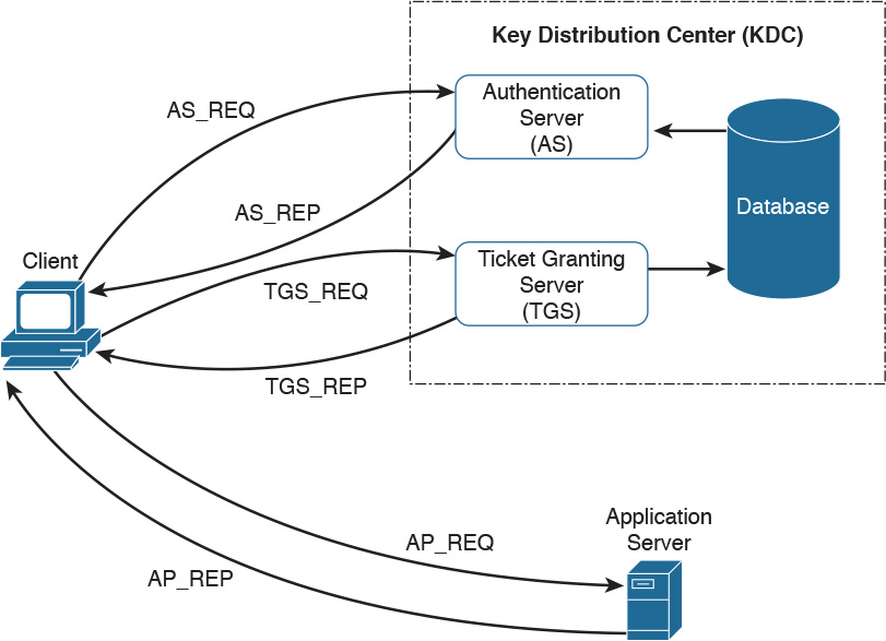
In its basic implementation, when a principal (for example, a user) requests access to another principal (for example, a server), it sends a request (AS_REQ) to the authentication server (AS) that includes its identity and the principal identifier of the server it wants to access. The AS checks that the client and server exist in the Kerberos database, generates a session key, and creates a response (AS_RES) that includes a ticket-granting ticket (TGT).
At this point, the client principal is ready to send a request (TGS_REQ) to the TGS to obtain a session ticket. This request includes the TGT and the authenticator. The TGS verifies that the principal server exists in the Kerberos database and then issues a service ticket that is then sent with its reply (TGS_REP) to the client principal that also includes a session key. The client principal can now request access to the server principal (AP_REQ), which includes the service ticket and the new authenticator built based on the new session key. The server may reply with an AP_REP that has information proving the server’s identity, if mutual authentication is required.
Figure 5-7 shows an example of authentication and authorization using Kerberos.
Federated SSO
A further evolution of the SSO model within a single organization is a model where a user can authenticate once and then have access to resources across multiple organizations not managed under the same IAM system. A federation is a collection of distinct organizations that agree to allow users to use one set of credential for authentication and authorization purposes. The identity used by the users across organizations is called a federated identity.
At the base of the federation is the concept of trust between the organization entities. In fact, each organization should trust that the authentication and authorization process is carried out in a secure way by the party providing that service.
The concept of federation has been further formalized by introducing the following concepts:
![]() Principal: The end user who requests service from a service provider and whose identity can be authenticated.
Principal: The end user who requests service from a service provider and whose identity can be authenticated.
![]() Service provider (SP): In some cases also called the relying party (RP). Defined as the system entity that provides service to the principal or other entities in the federation.
Service provider (SP): In some cases also called the relying party (RP). Defined as the system entity that provides service to the principal or other entities in the federation.
![]() Identity provider (IdP): The service provider that also manages the authentication and authorization process on behalf of the other systems in the federation.
Identity provider (IdP): The service provider that also manages the authentication and authorization process on behalf of the other systems in the federation.
![]() Assertion: The information produced by the authentication authority (for example, the IdP). It is usually provided to the SP to allow the user to access its resource. The assertion proves that the user has been authenticated and includes additional user attributes and authorization directives.
Assertion: The information produced by the authentication authority (for example, the IdP). It is usually provided to the SP to allow the user to access its resource. The assertion proves that the user has been authenticated and includes additional user attributes and authorization directives.
In a federation context, an SP can rely on multiple IdPs, and one IdP can serve multiple SPs. When a user wants to access resources with one SP, the SP determines which IdP to use to authenticate the user. The choice happens based on the user identifier or preference (for example, the user may indicate a specific IdP), or the choice happens based on the domain name associated with the user email address. This process is called discover of identity.
The SP will then redirect the user to the IdP for the authentication process. Once the user is authenticated, the IdP will generate an assertion that proves the identity and includes additional info about the user and authorization information.
Figure 5-8 shows a similar example as Figure 5-6; however, in this case, the user will authenticate with an SSO server that is in a different organization than the one in Server B, which will provide service to the user it belongs to. In this case, the SSO server acts as the IdP, and Server B is the SP.
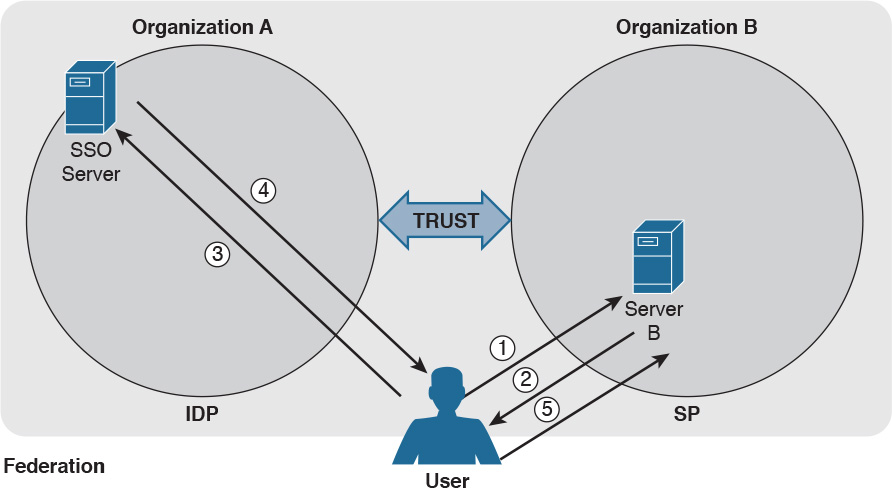
As in Figure 5-6, the user sends a request to Server B (step 1), which redirects the user to the SSO server for authentication (steps 2 and 3). The user then authenticates with the SSO server and receives proof of authentication, the assertion, which is provided to Server B (steps 4 and 5). Server B, after verifying the information in the assertion, grants access to resources.
Several protocols and frameworks are currently used to implement SSO and identity federation: SAML, OAuth2, and OpenID Connect are popular examples.
Security Assertion Markup Language
The OASIS Security Assertion Markup Language (SAML) standard is currently the most used standard for implementing federated identity processes. SAML is an XML-based framework that describes the use and exchange of SAML assertions in a secure way between business entities. The standard describes the syntax and rules to request, create, use, and exchange these assertions.
The SAML process involves a minimum two entities, the SAML assertion party (or SAML authority), which is the entity that produces the assertion, and the SAML relying party, which is the entity that uses the assertion to make access decisions.
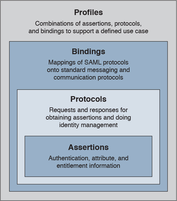
An assertion is the communication of security information about a subject (also called a principal) in the form of a statement. The basic building blocks of SAML are the SAML assertion, SAML protocol, SAML binding, and SAML profile. SAML assertions can contain the following information:
![]() Authentication statement: Includes the result of the authentication and additional info such as the authentication method, timestamps, and so on
Authentication statement: Includes the result of the authentication and additional info such as the authentication method, timestamps, and so on
![]() Attribute statement: Includes attributes about the principal
Attribute statement: Includes attributes about the principal
![]() Authorization statement: Includes information on what the principal is allowed to do
Authorization statement: Includes information on what the principal is allowed to do
An example of an assertion would be User A, who has the email address [email protected] authenticated via username and password, is a platinum member and is authorized for a 10% discount.
SAML protocols define the protocols used to transfer assertion messages. SAML bindings include information on how lower-level protocols (such as HTTP or SOAP) transport SAML protocol messages. SAML profiles are specific combinations of assertions, protocols, and bindings for specific use cases. Examples of profiles include Web Browser Single Sign-On, Identity Provider Discovery, and Enhanced Client and Proxy (ECP).
Figure 5-9 shows the SAML building blocks.
SAML also defines the concepts of identity provider and service provider.
SAML can work in two different ways:
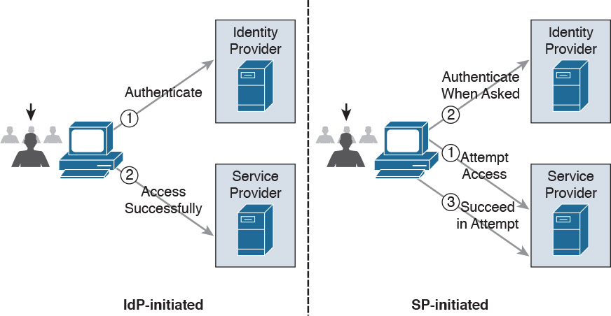
![]() In IdP initiated mode, a user is already authenticated on the IdP and requests a service from the SP (for example, by clicking a link on the IdP website). The IdP will build an assertion that is sent to the SP within the user request to the SP itself.
In IdP initiated mode, a user is already authenticated on the IdP and requests a service from the SP (for example, by clicking a link on the IdP website). The IdP will build an assertion that is sent to the SP within the user request to the SP itself.
For example, a user who is authenticated on an airline website decides to book a rental car by clicking a link on the airline website. The airline IAM system, which assumes the role of an IdP, will send assertion information about the user to the rental car IAM, which in turn will authenticate the user and provide access rights based on the information in the assertion.
![]() In SP initiated mode, a user initiates an access request to some resource on the SP. Because the federated identity is managed by a different IdP, the SP redirects the user to log in at the IdP. After the login, the IdP will send a SAML assertion back to the SP.
In SP initiated mode, a user initiates an access request to some resource on the SP. Because the federated identity is managed by a different IdP, the SP redirects the user to log in at the IdP. After the login, the IdP will send a SAML assertion back to the SP.
Figure 5-10 shows an example of IdP initiated mode (on the right) and SP initiated mode (on the left).
OAuth
OAuth is a framework that provides authorization to a third-party entity (for example, a smartphone application) to access resources hosted on a resource server. In a classic client-server authorization framework, the third-party entity would receive the credentials from the resource owner (user) and then access the resource on the resource server.
The main issue OAuth resolves is providing the third-party entity authorization to access restricted resources without passing to this third party the client credentials. Instead of getting the user credentials, the entity requesting access will receive an authorization token that includes authorization information, such as scope, duration, and so on, and that will be used to request access to a resource hosted by the resource server. The OAuth schema is usually called delegation of access.
OAuth2, defined in RFC 6749, includes four main roles:
![]() Resource owner: The party that owns the resource (for example, a user) and that will grant authorization to access some of its resources
Resource owner: The party that owns the resource (for example, a user) and that will grant authorization to access some of its resources
![]() Client: The party that requires access to a specific resource
Client: The party that requires access to a specific resource
![]() Resource server: The party that hosts or stores the resource
Resource server: The party that hosts or stores the resource
![]() Authorization server: The party that provides an authorization token
Authorization server: The party that provides an authorization token
In the basic scenario, the authorization is done with six messages:
1. The client sends an authorization request to the resource owner or indirectly to the authorization server.
2. The resource owner (or the authorization server on behalf of the resource owner) sends an authorization grant to the client.
3. The client sends the authorization grant to the authorization server as proof that authorization was granted.
4. The authorization server authenticates the client and sends an access token.
5. The client sends the access token to the resource server as proof of authentication and authorization to access the resources.
6. The resource server validates the access token and grants access.
For example, a user (the resource owner) may grant access to her personal photos hosted at some online storage provider (the resource server) to an application on her mobile phone (the client) without directly providing her credentials to the application but instead by directly authenticating with the authorization server (in this case, also the online storage provider) and authorizing the access.
Figure 5-11 shows an example of an OAuth exchange.

OpenID Connect
OpenID has been a very popular SSO protocol for federated systems for quite some time. In the 2.0 version, the authentication and authorization process is similar to the one in SAML. OpenID also defines an IdP, called the OpenID provider (OP), and a relying party (RP), which is the entity that holds the resource the user wants to access. In OpenID, a user is free to select an OP of her choice, and the initial identity is provided in a form of a URL.
Version 2.0 has been superseded by OpenID Connect. This version drops the authorization functionality present in version 2.0 and is designed to work with OAuth 2.0 for deployments. In practice, OpenID Connect operates as an authentication profile for OAuth. In OpenID Connect, when a user tries to access resources on an RP, the RP will send an authentication request to the OP for that user. In practice, this is an OAuth 2.0 authorization request to access the user’s identity at the OP. The authentication request can be of three types:
![]() Authorization code flow (the most commonly used)
Authorization code flow (the most commonly used)
![]() Implicit flow
Implicit flow
![]() Hybrid flow
Hybrid flow
In an authorization code flow scenario, once the user authenticates with the OP, the OP will ask the user for consent and issue an authorization code that the user will then send to the RP. The RP will use this code to request an ID token and access token from the OP, which is the way the OP provides assertion to the RP.
Security Events and Logs Management
Systems within an IT infrastructure are often configured to generate and send information every time a specific event happens. An event, as described in NIST SP 800-61r2, is any observable occurrence in a system or network, whereas a security incident is an event that violates the security policy of an organization. One important task of a security operation center analyst is to determine when an event constitutes a security incident. An event log (or simply a log) is a formal record of an event and includes information about the event itself. For example, a log may contain a timestamp, an IP address, an error code, and so on.
Event management includes administrative, physical, and technical controls that allow for the proper collection, storage, and analysis of events. Event management plays a key role in information security because it allows for the detection and investigation of a real-time attack, enables incident response, and allows for statistical and trending reporting. If an organization lacks information about past events and logs, this may reduce its ability to investigate incidents and perform a root-cause analysis.
An additional important function of monitoring and event management is compliance. Many compliance frameworks (for example, ISO and PCI DSS) mandate log management controls and practices.
Logs Collection, Analysis, and Disposal
One of the most basic tasks of event management is log collection. Many systems in the IT infrastructure are in fact capable of generating logs and sending them to a remote system that will store them. Log storage is a critical task for maintaining log confidentiality and integrity. Confidentiality is needed because the logs may contain sensitive information. In some scenarios, logs may need to be used as evidence in court or as part of an incident response. The integrity of the logs is fundamental for them to be used as evidence and for attribution.
The facilities used to store logs need to be protected against unauthorized access, and the logs’ integrity should be maintained. Enough storage should be allocated so that the logs are not missed due to lack of storage.
The information collected via logs usually includes, but is not limited to, the following:
![]() User ID
User ID
![]() System activities
System activities
![]() Timestamps
Timestamps
![]() Successful or unsuccessful access attempts
Successful or unsuccessful access attempts
![]() Configuration changes
Configuration changes
![]() Network addresses and protocols
Network addresses and protocols
![]() File access activities
File access activities
Different systems may send their log messages in various formats, depending on their implementation. According to NIST SP 800-92, three categories of logs are of interest for security professionals:
![]() Logs generated by security software: This includes logs and alerts generated by the following software and devices:
Logs generated by security software: This includes logs and alerts generated by the following software and devices:
![]() Antivirus/antimalware
Antivirus/antimalware
![]() IPS and IDS
IPS and IDS
![]() Web proxies
Web proxies
![]() Remote access software
Remote access software
![]() Vulnerability management software
Vulnerability management software
![]() Authentication servers
Authentication servers
![]() Infrastructure devices (including firewalls, routers, switches, and wireless access points)
Infrastructure devices (including firewalls, routers, switches, and wireless access points)
![]() Logs generated by the operating system: This includes the following:
Logs generated by the operating system: This includes the following:
![]() System events
System events
![]() Audit records
Audit records
![]() Logs generated by applications: This includes the following:
Logs generated by applications: This includes the following:
![]() Connection and session information
Connection and session information
![]() Usage information
Usage information
![]() Significant operational action
Significant operational action
Once collected, the logs need to be analyzed and reviewed to detect security incidents and to make sure security controls are working properly. This is not a trivial task because the analyst may need to analyze an enormous amount of data. It is important for the security professional to understand which logs are relevant and should be collected for the purpose of security administration, event, and incident management.
Systems that are used to collect and store the logs usually offer a management interface through which the security analyst is able to view the logs in an organized way, filter out unnecessary entries, and produce historical reporting. At some point, logs may not be needed anymore. The determination of how long a log needs to be kept is included in the log retention policy. Logs can be deleted from the system or archived in separate systems.
Syslog
One of the most used protocols for event notification is syslog, which is defined in RFC 5424. The syslog protocol specifies three main entities:
![]() Originator: The entity that generates a syslog message (for example, a router)
Originator: The entity that generates a syslog message (for example, a router)
![]() Collector: The entity that receives information about an event in syslog format (for example, a syslog server)
Collector: The entity that receives information about an event in syslog format (for example, a syslog server)
![]() Relay: An entity that can receive messages from originators and forward them to other relays or collectors
Relay: An entity that can receive messages from originators and forward them to other relays or collectors
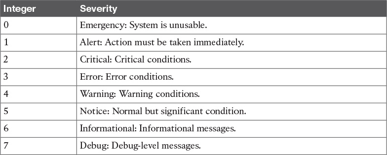
The syslog protocol is designed not to provide acknowledgement and can use both UDP on port 514 and TCP on port 514 as transport methods. Security at the transport layer can be added by using DTLS or TLS. Two additional concepts that are not part of the RFC but are commonly used are the facility code and the severity code. The facility code indicates the system, process, or application that generated the syslog. The syslog facilities are detailed in Table 5-3.

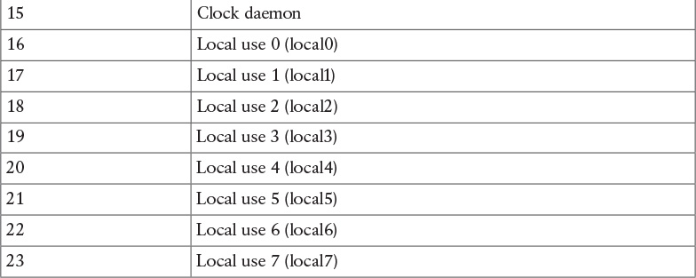
The syslog server can use the facility number to classify the syslog message. Usually applications that do not map to a predefined facility can use any of the local use facilities (local0 through local7). For example, Cisco ASA allows the user to set the facility number, meaning the user can specify which local facility to use. The default facility used by Cisco ASA is 20 (local4).
The severity code represents the severity of the message. Table 5-4 shows the severity code associated to each severity level.
The header of a syslog message contains, among other things, the following important information:
![]() Priority (PRI): The priority is obtained by combining the numerical code of the facility and the severity. The formula to obtain the PRI is as follows:
Priority (PRI): The priority is obtained by combining the numerical code of the facility and the severity. The formula to obtain the PRI is as follows:
Facility × 8 + Severity
For example, a message with a facility code of security/authorization messages (code 4) and a severity code of critical (code 2) will receive a PRI of 34.
![]() Timestamp
Timestamp
![]() Hostname
Hostname
![]() Application name
Application name
![]() Process ID
Process ID
The message carried within the syslog can be any text message. The following shows an example of a syslog message generated from a Cisco ASA following the detection of a malicious pattern in an SMTP message:
Aug 19 2016 18:13:29 ASACCNA : %ASA-2-108003: Terminating ESMTP/SMTP connection;
malicious pattern detected in the mail address from
source_interface:source_address/source_port to
dest_interface:dest_address/dset_port. Data: string
The message starts with the timestamp “Aug 19 2016 18:13:29” and the hostname. Both are not sent by default but can be configured. Also, “%ASA-2-108003” specifies the syslog severity (2) and a specific message identifier (108003). The last part includes the text message with the information about the event.
Security Information and Event Manager
The Security Information and Event Manager (SIEM) is a specialized device or software for security event management. It typically allows for the following functions:
![]() Log collection: This includes receiving information from devices with multiple protocols and formats, storing the logs, and providing historical reporting and log filtering.
Log collection: This includes receiving information from devices with multiple protocols and formats, storing the logs, and providing historical reporting and log filtering.
![]() Log normalization: This function extracts relevant attributes from logs received in different formats and stores them in a common data model or template. This allows for faster event classification and operations. Non-normalized logs are usually kept for archive, historical, and forensic purposes.
Log normalization: This function extracts relevant attributes from logs received in different formats and stores them in a common data model or template. This allows for faster event classification and operations. Non-normalized logs are usually kept for archive, historical, and forensic purposes.
![]() Log aggregation: This function aggregates information based on common information and reduces duplicates.
Log aggregation: This function aggregates information based on common information and reduces duplicates.
![]() Log correlation: This is probably one of most important functions of an SIEM. It refers to the ability of the system to associate events gathered by various systems, in different formats and at different times, and create a single actionable event for the security analyst or investigator. Often the quality of an SIEM is related to the quality of its correlation engine.
Log correlation: This is probably one of most important functions of an SIEM. It refers to the ability of the system to associate events gathered by various systems, in different formats and at different times, and create a single actionable event for the security analyst or investigator. Often the quality of an SIEM is related to the quality of its correlation engine.
![]() Reporting: Event visibility is also a key functionality of an SIEM. Reporting capabilities usually include real-time monitoring and historical base reports.
Reporting: Event visibility is also a key functionality of an SIEM. Reporting capabilities usually include real-time monitoring and historical base reports.
Most modern SIEMs also integrate with other information systems to gather additional contextual information to feed the correlation engine. For example, they can integrate with an identity management system to get contextual information about users or with NetFlow collectors to get additional flow-based information. Respectively, Cisco ISE and Cisco Stealthwatch are examples of an identity management system and flow collector that are able to integrate with most of the SIEM systems.
Several commercial SIEM systems are available. Cisco partners with several vendors that offer seamless integration with Cisco products. Here’s a list of some SIEM solutions from Cisco partners:
![]() HP ArcSight
HP ArcSight
![]() BlackStratus
BlackStratus
![]() Hawk Network Defense
Hawk Network Defense
![]() Log Rhythm
Log Rhythm
![]() NetIQ
NetIQ
![]() IBM QRadar
IBM QRadar
![]() RSA
RSA
![]() Splunk
Splunk
![]() Symantec
Symantec
![]() TrustWave
TrustWave
Figure 5-12 shows a typical deployment of an SIEM and summarizes the SIEM key capabilities.

The following summarizes the key concepts of log collection and SIEM:
![]() Logs collection is the process of collecting and organizing logs for analysis. A log collector is software that is able to receive logs from multiple sources and in some cases offers storage capabilities and log analysis functionality.
Logs collection is the process of collecting and organizing logs for analysis. A log collector is software that is able to receive logs from multiple sources and in some cases offers storage capabilities and log analysis functionality.
![]() SIEM is a specialized device or software for security event management. It increases the normal log collector functionality by providing log collection, normalization, aggregation, correlation, and reporting capabilities.
SIEM is a specialized device or software for security event management. It increases the normal log collector functionality by providing log collection, normalization, aggregation, correlation, and reporting capabilities.
Assets Management
Assets are key components of an organization and, as such, should be protected. An asset can be defined as anything that has value for the organization. In simple terms, an asset can be any organization resource, including personnel, hardware, software, building, and data.
Assets should be protected appropriately against unauthorized access and from any threat that could compromise the confidentiality, integrity, and availability. Asset management is a broad term that defines procedures and policies to manage an organization’s assets throughout their lifecycle. In information security, asset management refers to administrative, physical, and technical control to protect assets within an organization.
ISO 27001 mandates several controls that are applicable to asset management. In the context of information security, asset management usually includes policies and processes around assets inventory, ownership of the assets, acceptable use and return policies, assets classification, asset labeling, asset and information handling, and media management.
A high-level view of asset management in the context of access controls that was provided in Chapter 4.
The following list summarizes the key concepts and phases of secure assets management:
![]() Assets management in information security refers to policies, processes, and technologies to manage and protect an organization’s assets during their lifecycle.
Assets management in information security refers to policies, processes, and technologies to manage and protect an organization’s assets during their lifecycle.
![]() Assets inventory deals with collecting and storing information about assets, such as location, security classification, and owner.
Assets inventory deals with collecting and storing information about assets, such as location, security classification, and owner.
![]() Assets acceptable use and return policies specify how users can use an asset and how an asset should be returned when it is not needed anymore.
Assets acceptable use and return policies specify how users can use an asset and how an asset should be returned when it is not needed anymore.
![]() Assets ownership is the process of assigning an owner to an asset. Each asset within the organization needs an owner. The owner is responsible for the security of the asset during its lifecycle.
Assets ownership is the process of assigning an owner to an asset. Each asset within the organization needs an owner. The owner is responsible for the security of the asset during its lifecycle.
![]() Assets classification is the process of evaluating the risk of an asset in terms of confidentiality, integrity, and availability and assigning a security classification to an asset.
Assets classification is the process of evaluating the risk of an asset in terms of confidentiality, integrity, and availability and assigning a security classification to an asset.
![]() Assets labeling is the process of assigning a label to an asset that includes its security classification.
Assets labeling is the process of assigning a label to an asset that includes its security classification.
![]() Assets handling refers to procedures and technologies that allow for the secure storage, use, and transfer of an asset.
Assets handling refers to procedures and technologies that allow for the secure storage, use, and transfer of an asset.
![]() Media management deals with the secure management of the media lifecycle, which includes media access, media marking, media storage, media use, media transport, media downgrading, and media sanitization and disposal.
Media management deals with the secure management of the media lifecycle, which includes media access, media marking, media storage, media use, media transport, media downgrading, and media sanitization and disposal.
Let’s review each of these items in more detail.
Assets Inventory
Organizations need to have a clear understanding of which assets are part of the organization and what they are used for. According to ISO 27005, assets can be classified as primary and supporting assets. Primary assets include the following:
![]() Business processes and activities (for example, processes or activities that enable the organization or business to deal with secret and proprietary information)
Business processes and activities (for example, processes or activities that enable the organization or business to deal with secret and proprietary information)
![]() Information (for example, personal or strategic information)
Information (for example, personal or strategic information)
Supporting assets include the following:
![]() Hardware (for example, laptops)
Hardware (for example, laptops)
![]() Software (for example, operating systems and licenses)
Software (for example, operating systems and licenses)
![]() Network (for example, infrastructure devices such as routers and switches)
Network (for example, infrastructure devices such as routers and switches)
![]() Personnel (for example, users)
Personnel (for example, users)
![]() Sites (for example, locations)
Sites (for example, locations)
![]() Organizational structure (for example, external organizations)
Organizational structure (for example, external organizations)
Not all assets need to be part of an inventory of security assets, and the security professional would need to provide feedback on what should and should not be part of the inventory. Asset inventory should be as accurate as possible and may need regular review to reflect the current state. It should include information about the location of the asset, the asset description, the asset owner, the asset classification, and the asset configuration. An asset inventory should include both physical and virtual assets and on-premises and cloud-based assets. An asset inventory is also a component of other management processes, such as configuration management, which is described later in this chapter.
Assets Ownership
Each asset should have an owner. The owner can be an individual or an entity within the organization. The owner is assigned at asset creation, asset acquisition, or when the asset is transferred. The asset owner is responsible for the following tasks:
![]() Ensuring proper inventory of the assets she owns
Ensuring proper inventory of the assets she owns
![]() Asset classification
Asset classification
![]() Ensuring that the assets are protected appropriately
Ensuring that the assets are protected appropriately
![]() Periodically reviewing the asset classification and access control policies, including privileges on the assets
Periodically reviewing the asset classification and access control policies, including privileges on the assets
![]() Ensuring proper disposal of the assets
Ensuring proper disposal of the assets
The asset owner, together with senior management, is responsible for the asset through its entire lifecycle. The owner can delegate day-to-day operations to a custodian. Roles and duties within information security were discussed in more detail in Chapter 4.
Assets Acceptable Use and Return Policies
Users of an asset should receive information about rules for accessing and using a specific asset. The rules should describe user responsibility and expected behavior. An organization may ask users to sign an acknowledgment that they have read and understood the acceptable use rules before being granted access to the asset. The user may be held responsible for any misuse of the assets or use against the security organization policy.
A return policy and process should be established for the time when the asset is not needed anymore by the user. For example, this may be due to employee termination or transfer to another organization, ending of a contract agreement, and so on. The Return policy should consider physical assets and assets in electronic form. If a user uses personal devices for business, the policy should include information on how to properly transfer the information contained on these devices.
Assets Classification
Assets should be classified based on the risk to the organization that an unauthorized access can cause to the confidentiality, integrity and availability. The asset classification is assigned by the asset owner, and it influences the level of protection the asset receives.
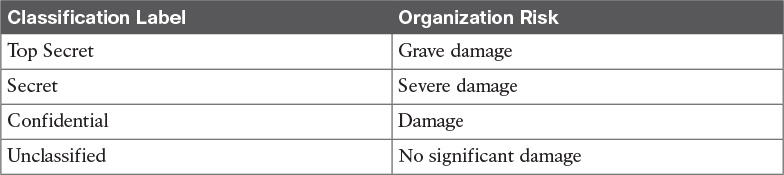
The classification policies and processes should include information on the classification schema (for example, the name of the labels) and about the process for changing the classification when the value and risk associated with an asset changes. The classification schema should include labels that are associated with the related risk for the organization. For example, the label “Top Secret” is associated with “grave damage to the organization.”
Table 5-5 outlines a sample classification schema that’s generally used in military and governmental organizations. Assets classification was discussed in more detail in Chapter 4.
Assets Labeling
Assets labeling includes processes for marking an asset with information about its security classification. The label should be visible so that users are aware of a specific classification and can handle the asset accordingly. The process can also include exceptions (for example, in which occasion a label can be omitted).
Assets and Information Handling
The asset owner should identify procedures and processes for securely handling assets. The cases of an asset at rest, an asset in use, and an asset being transferred (in motion) need to be taken into consideration. The handling processes usually include the following:
![]() Access controls and restrictions to match the security classification
Access controls and restrictions to match the security classification
![]() Maintenance of access records and auditing
Maintenance of access records and auditing
![]() Protection of any temporary copies of the assets
Protection of any temporary copies of the assets
![]() Storage of the assets that conforms with vendor guidelines
Storage of the assets that conforms with vendor guidelines
Access controls were discussed in Chapter 4.
Media Management
Media is a category of asset used to store information. If the information stored is sensitive, the media needs to be handled with special care. Media management deals with policies and procedures for protecting and securely handling media. It includes information on media access, media marking, media storage, media use, media transport, media downgrading, and media sanitization and disposal.
Removable media refers to media that can be used and removed while the system is still in use. Examples of removable media are USB, DVD, and external HD. These constitutes a higher risk for the organization because they are easily portable, so there is a higher chance of media theft or loss. The media management should include procedures for handling removable media, including processes for securely erasing the information stored, mitigating the risk of media degradation, cryptographic technology for information storage, and registration of removable media.
Media sanitization and disposal are also important parts of media management. At the end of the media lifecycle, the media should be sanitized and disposed of securely to avoid theft of any information that might still be present on the media. Depending on the classification of the information stored on the media, different methods of sanitization and disposal might be required.
Additional information about media and asset disposal is provided in Chapter 4.
Introduction to Enterprise Mobility Management
Mobile assets are a special class of assets that allow mobility and seamless connectivity to an organization’s infrastructure. Mobile assets or devices usually include laptops, tablets, smartphones, and mobile phones. In the last few years, the security of mobile assets has become a hot topic due to the increased use of mobile devices to perform business tasks. In addition, organizations are more and more adopting the bring-your-own-device (BYOD) philosophy that allows employees to use their own personal device to access and consume an organization’s assets.
There are several reasons for the spread of the BYOD philosophy across organizations; however, the primary reason is that BYOD increases employee and organizational productivity because employees are empowered to work from wherever and at whatever time they want. The spread of the use of mobile devices and specifically personally owned devices, however, has created several security gaps and new threats to the organization.
NIST SP 800-124 identifies several threats to the organization due to the use of mobile devices:
![]() Lack of physical security controls: Mobile devices can be used anywhere outside of the organization, including in coffee shops, at home, in a hotel, and on a train. The risk of a device being stolen or lost is much higher compared to assets that cannot be used outside the organization’s perimeter.
Lack of physical security controls: Mobile devices can be used anywhere outside of the organization, including in coffee shops, at home, in a hotel, and on a train. The risk of a device being stolen or lost is much higher compared to assets that cannot be used outside the organization’s perimeter.
![]() Use of untrusted devices: Mobile devices, especially those that are personally owned, may not be fully trusted. For example, a personal mobile device could be rooted or jailbroken, thus increasing the risk for device compromise.
Use of untrusted devices: Mobile devices, especially those that are personally owned, may not be fully trusted. For example, a personal mobile device could be rooted or jailbroken, thus increasing the risk for device compromise.
![]() Use of untrusted networks: Mobile devices can connect from everywhere, including untrusted networks, for Internet access. For example, an employee might attempt to connect to a public Wi-Fi hotspot from a coffee shop that could be compromised.
Use of untrusted networks: Mobile devices can connect from everywhere, including untrusted networks, for Internet access. For example, an employee might attempt to connect to a public Wi-Fi hotspot from a coffee shop that could be compromised.
![]() Use of untrusted applications: Mobile devices and especially smartphones enable users to install third-party applications that in some cases interact with corporate information stored on the device itself, or with organization resources over the network. These applications are untrusted and potentially dangerous.
Use of untrusted applications: Mobile devices and especially smartphones enable users to install third-party applications that in some cases interact with corporate information stored on the device itself, or with organization resources over the network. These applications are untrusted and potentially dangerous.
![]() Interaction with other systems: Mobile devices often interact with other systems for data exchange. For example, a smartphone can connect to a laptop for backup or even perform a data backup via the network with various cloud backup systems. These systems are often not under the control of the organization and are potentially untrusted. The risk of data loss for an organization is, therefore, increased.
Interaction with other systems: Mobile devices often interact with other systems for data exchange. For example, a smartphone can connect to a laptop for backup or even perform a data backup via the network with various cloud backup systems. These systems are often not under the control of the organization and are potentially untrusted. The risk of data loss for an organization is, therefore, increased.
![]() Use of untrusted content: Mobile devices can access content in various ways that are not available for other types of devices. For example, a website URL can be specified in the form of a Quick Response (QR) code. This increases the risk because the user, who might understand the risk of clicking an untrusted URL link, might not understand the risk of scanning an untrusted QR code.
Use of untrusted content: Mobile devices can access content in various ways that are not available for other types of devices. For example, a website URL can be specified in the form of a Quick Response (QR) code. This increases the risk because the user, who might understand the risk of clicking an untrusted URL link, might not understand the risk of scanning an untrusted QR code.
![]() Use of location services: Location services used by mobile devices allow tracking of information and user location. This could help an attacker locate a specific asset or person and use the information to build up an attack.
Use of location services: Location services used by mobile devices allow tracking of information and user location. This could help an attacker locate a specific asset or person and use the information to build up an attack.
In response to organizations implementing BYOD and the corresponding need to manage the new threats inherited by this choice, several new technologies have emerged. Enterprise Mobility Management (EMM) includes policies, processes, and technologies that allow for the secure management of mobile devices. Technologies that enable BYOD, Mobile Device Management (MDM), and Mobile Applications Management (MAM) are examples of areas covered by an organization’s EMM.
NIST SP 800-124 proposes a five-phase lifecycle model for an enterprise mobile device solution:
1. Initiation: Includes the activities an organization needs to perform before designing a mobile device solution. This includes selecting the strategy for implementation, determining how the strategy matches the organization’s mission, developing a mobile device security policy, and so on.
2. Development: In this phase, the technical characteristics and deployment plan of the mobile solution are specified. It includes which authentication or encryption strategy will be used, the type of mobile brands that will be allowed, and so on.
3. Implementation: In this phase, mobile devices are being provisioned to meet the security policy requirements. This phase includes the testing and the production deployment of the solution.
4. Operation and maintenance: This includes ongoing security tasks that need to be performed during the mobile device’s lifecycle. Examples are reviewing access controls, managing patches, threat detection and protection, and so on.
5. Disposal: This includes all the activities around media disposal, such as media sanitization and destruction. Asset disposal was discussed in the Asset Management section of this chapter.
Figure 5-13 shows the five phases of an EMM solution lifecycle.

Mobile Device Management
Mobile device management (MDM) controls the deployment, operations, and monitoring of mobile devices used to access organization resources. It is used to enforce an organization’s security policy on mobile devices. It includes all or part of the following capabilities:
![]() Restrict user or application access to mobile device hardware, such as digital cameras, network interfaces, GPS, and services or native applications such as the built-in web browser or email client.
Restrict user or application access to mobile device hardware, such as digital cameras, network interfaces, GPS, and services or native applications such as the built-in web browser or email client.
![]() Limit or prevent access to organization resources based on the device profile and security posture (for example, a device that is rooted should not be able to access certain resources).
Limit or prevent access to organization resources based on the device profile and security posture (for example, a device that is rooted should not be able to access certain resources).
![]() Monitor, alert, and report on policy violation (for example, if a user is trying to root the mobile device).
Monitor, alert, and report on policy violation (for example, if a user is trying to root the mobile device).
![]() Encrypt data communication between the device and the organization as well as data stored on the device or in removable storage.
Encrypt data communication between the device and the organization as well as data stored on the device or in removable storage.
![]() Provide the ability to remotely wipe the device in case the device is lost or stolen, and in case of device reuse.
Provide the ability to remotely wipe the device in case the device is lost or stolen, and in case of device reuse.
![]() Enforce strong password or PIN code authentication for accessing the device and/or organization resources. This includes password strength policies, clipping level, and so on.
Enforce strong password or PIN code authentication for accessing the device and/or organization resources. This includes password strength policies, clipping level, and so on.
![]() Remotely lock the device and remotely reset the password.
Remotely lock the device and remotely reset the password.
![]() Enable the enforcement of data loss prevention (DLP) on mobile devices.
Enable the enforcement of data loss prevention (DLP) on mobile devices.
![]() Restrict the type of applications that can be installed (for example, via whitelisting or blacklisting) and which resources the applications can use. Due to the large threat untrusted applications may pose to the organization, application management is usually handled within a mobile application management (MAM) framework.
Restrict the type of applications that can be installed (for example, via whitelisting or blacklisting) and which resources the applications can use. Due to the large threat untrusted applications may pose to the organization, application management is usually handled within a mobile application management (MAM) framework.
Mobile device management capabilities could be offered by the mobile vendor or provided by a third-party management tool that offers multivendor support. The second option is currently the most used due to the increased adoption of BYOD and heterogeneous types of devices used within an organization.
One of the characteristics of an MDM solution is the use of over-the-air (OTA) device management. OTA historically refers to the deployment and configuration performed via a messaging service, such as Short Message Service (SMS), Multimedia Messaging Service (MMS), or Wireless Application Protocol (WAP). Nowadays it’s used to indicate remote configuration and deployment of mobile devices.
The Cisco Unified Access validated design recommends two different deployment models for an MDM solution. In the on-premises model, the MDM server and application reside inside the organization perimeter, usually in a DMZ close to the Internet edge or in the organization’s data center. The organization’s IT department is responsible for operating the MDM solution. This model suits most organizations with experienced IT units. In the cloud-based model, the MDM solution is deployed as a service and operated by a third party from the cloud. The advantages of a cloud-based model are as follows:
![]() The cost of the solution and deployment
The cost of the solution and deployment
![]() The flexibility
The flexibility
![]() Speed of deployment
Speed of deployment
![]() Scalability
Scalability
![]() Easy to use and maintain
Easy to use and maintain
And here are the advantages of the on-premises model:
![]() Higher level of control
Higher level of control
![]() Intellectual property retention
Intellectual property retention
![]() Regulatory compliance (for example, if it is not possible to store data on the cloud)
Regulatory compliance (for example, if it is not possible to store data on the cloud)
In terms of security, both solutions have pros and cons, as outlined in Table 5-6; however, the security depends largely on the security maturity level of the IT workforce for the on-premises model or the security maturity level of the third party that operates the cloud-based MDM.

Cisco BYOD Architecture
The Cisco Unified Access validated design offers an end-to-end architecture for implementing BYOD within an organization. Here are the main components of the BYOD architecture:
![]() Mobile devices: These can be any corporate-owned or personally-owned mobile devices that require access to corporate resources. Examples are laptops, smartphones, and tablets.
Mobile devices: These can be any corporate-owned or personally-owned mobile devices that require access to corporate resources. Examples are laptops, smartphones, and tablets.
![]() Wireless access points (APs): Cisco wireless APs provide wireless connectivity to the corporate network.
Wireless access points (APs): Cisco wireless APs provide wireless connectivity to the corporate network.
![]() Wireless LAN (WLAN) controllers: Cisco WLAN controllers (WLCs) serve as a centralized point for the configuration, management, and monitoring of the Cisco WLAN solution. These are also used to enforced authorization policies to the endpoints that require access.
Wireless LAN (WLAN) controllers: Cisco WLAN controllers (WLCs) serve as a centralized point for the configuration, management, and monitoring of the Cisco WLAN solution. These are also used to enforced authorization policies to the endpoints that require access.
![]() Identity Services Engine (ISE): The Cisco ISE is the critical component of a BYOD solution and provides identity management and profiling services, including authentication, authorization, accounting, and access controls.
Identity Services Engine (ISE): The Cisco ISE is the critical component of a BYOD solution and provides identity management and profiling services, including authentication, authorization, accounting, and access controls.
![]() Cisco AnyConnect Secure Mobility Client: The software installed on the mobile device that provides client-side authentication and authorization services by using 802.1x when on the premises and enabling VPN access when used outside the premises.
Cisco AnyConnect Secure Mobility Client: The software installed on the mobile device that provides client-side authentication and authorization services by using 802.1x when on the premises and enabling VPN access when used outside the premises.
![]() Integrated Services Routers (ISRs): Cisco ISRs provide Internet access for home offices and branch locations.
Integrated Services Routers (ISRs): Cisco ISRs provide Internet access for home offices and branch locations.
![]() Image Aggregation Services Routers (ASRs): Cisco ASRs provide aggregation and Internet gateway functionality for campus networks and function as aggregators for home offices and branches that connect back to the corporate campus.
Image Aggregation Services Routers (ASRs): Cisco ASRs provide aggregation and Internet gateway functionality for campus networks and function as aggregators for home offices and branches that connect back to the corporate campus.
![]() Cloud Web Security (CWS): CWS provides worldwide threat intelligence, advanced threat defense capabilities, and roaming user protection. The Cisco CWS service uses web proxies in the Cisco cloud environment that scan traffic for malware and policy enforcement.
Cloud Web Security (CWS): CWS provides worldwide threat intelligence, advanced threat defense capabilities, and roaming user protection. The Cisco CWS service uses web proxies in the Cisco cloud environment that scan traffic for malware and policy enforcement.
![]() Adaptive Security Appliance (ASA): The Cisco ASA provides all the standard security functions for the BYOD solution at the Internet edge, including VPN servers, next-gen firewall services, and next-gen IPS services.
Adaptive Security Appliance (ASA): The Cisco ASA provides all the standard security functions for the BYOD solution at the Internet edge, including VPN servers, next-gen firewall services, and next-gen IPS services.
Here are some additional elements typically found in BYOD deployments:
![]() Cisco Converged Access Switches
Cisco Converged Access Switches
![]() Cisco Mobility Service Engine
Cisco Mobility Service Engine
![]() Cisco switches (Catalyst and Nexus series family)
Cisco switches (Catalyst and Nexus series family)
![]() Cisco Prime Infrastructure
Cisco Prime Infrastructure
![]() Corporate Directory Service (for example, AD or LDAP server)
Corporate Directory Service (for example, AD or LDAP server)
![]() Certificate authority and PKI services
Certificate authority and PKI services
Figure 5-14 provides an example of a BYOD infrastructure with an on-premises MDM solution.

Cisco ISE and MDM Integration
At press time, Cisco ISE does not include MDM functionality; however, it allows seamless integration with third-party MDM services and commercial tools both for on-premises and cloud-based deployments. Cisco ISE allows MDM integration via the Cisco MDM API and can be used to enforce mobile device policy and compliance.
By using the Cisco MDM API, the Cisco ISE is capable of pulling information from the MDM server (for example, for additional data points regarding an endpoint) or pushing administrative actions to the endpoint via the MDM service capabilities.
Here are some examples of supported capabilities:
![]() PIN lock check
PIN lock check
![]() Jailbreak check
Jailbreak check
![]() Data encryption check
Data encryption check
![]() Device augmentation information check
Device augmentation information check
![]() Registration status check
Registration status check
![]() Compliance status check
Compliance status check
![]() Periodic compliance status check
Periodic compliance status check
![]() (Full/Partial) remote wipe
(Full/Partial) remote wipe
![]() Remote PIN lock
Remote PIN lock
Cisco ISE supports a variety of third-party MDM vendors as well as Cisco Meraki device management. Figure 5-15 provides an example of Cisco ISE integration with cloud-based MDM solutions.

Cisco Meraki Enterprise Mobility Management
Cisco Meraki Enterprise Mobility Management (EMM) it is a cloud-based EMM solution that offers unified management, diagnostics, and monitoring of multiple types of mobile devices, including smartphones and laptops. It allows security policy enforcement, scalable configuration deployment, device classification and inventory, and device geolocation. It also allows for several types of secure device enrollment, such as fully automated, partially automated, and manual, and granular MDM access rights configuration.
Configuration and Change Management
Configuration and change management is a broad term that can have different meanings depending on the context in which it is used. In this book, we will define them as follows:
![]() Configuration management is concerned with all policies, processes, and technologies used to maintain the integrity of the configuration of a given asset.
Configuration management is concerned with all policies, processes, and technologies used to maintain the integrity of the configuration of a given asset.
![]() Change management is concerned with all policies, processes, and technologies that handle a change to an asset’s lifecycle.
Change management is concerned with all policies, processes, and technologies that handle a change to an asset’s lifecycle.
In some cases, configuration and change management are described as part of asset management.
Configuration Management
NIST SP 800-128 defines configuration management as a set of activities used to maintain organizational resource integrity through the control of processes for initializing, changing, and monitoring the resource configuration. A configuration item (CI) is defined as an identifiable part of the system that is the target of the configuration control process. A CI can be an information system component such as a router, application, server, or a group of components (for example, a group of routers sharing the same operating system and configuration), or it can be a noncomponent such as documentation or firmware. Each CI includes a set of attributes; for example, the attributes for a CI describing a server could be the firmware version and applications installed. If these attributes are configured as individual CIs, then two CIs are said to be “in relation.” For example, a Cisco router could be considered a CI, and the router operating system, IOS-XE 16.1.1, could be considered a separate CI. These two CIs are said to be “in relation.”
The set of attributes and relationships for a CI create a configuration record. The configuration record is stored in the configuration management database (CMDB). The main goal of configuration management is to manage the lifecycle of the CIs. An important step is the inventory of CIs. The inventory process is about identifying all the CIs and capturing the configuration records in the configuration management database.
Another important concept in configuration management is the baseline configuration. A baseline configuration is a set of attributes and CIs related to a system, which has been formally reviewed and approved. It can only be changed with a formal change process.
While configuration management goes beyond information security, it is an important part of the management of secure configurations, as well as to enable security and facilitate the assessment of the risk for an organization. Security-focused configuration management (SecCM), as described in NIST SP 800-128, should be built on top of normal configuration management and includes four main activities:
![]() Identification and recording of configurations that impact the security posture of a resource
Identification and recording of configurations that impact the security posture of a resource
![]() Consideration of the security risk when approving the initial configuration
Consideration of the security risk when approving the initial configuration
![]() Analysis of the security risk involved in a configuration change
Analysis of the security risk involved in a configuration change
![]() Documentation and approval of changes
Documentation and approval of changes
The process described in SecCM includes four main phases:
![]() Planning: Includes the definition of SecCM policies and procedures and the integration of these procedures within the IT and information security policy of an organization.
Planning: Includes the definition of SecCM policies and procedures and the integration of these procedures within the IT and information security policy of an organization.
![]() Identifying and implementing the configuration: Includes the development and establishment of security baseline configuration and the implementation of the baseline on CIs.
Identifying and implementing the configuration: Includes the development and establishment of security baseline configuration and the implementation of the baseline on CIs.
![]() Controlling the configuration changes: Includes the management of changes to keep the baseline configuration secure. Change management is further detailed in the next section.
Controlling the configuration changes: Includes the management of changes to keep the baseline configuration secure. Change management is further detailed in the next section.
![]() Monitoring: Used to validate and ensure that the CIs are compliant with the organization’s security policy and to maintain a secure baseline configuration.
Monitoring: Used to validate and ensure that the CIs are compliant with the organization’s security policy and to maintain a secure baseline configuration.
Planning
The main items of the planning phase include the following:
![]() Establish an organization-wide SecCM program.
Establish an organization-wide SecCM program.
![]() Develop an organizational SecCM policy.
Develop an organizational SecCM policy.
![]() Develop organizational SecCM procedures.
Develop organizational SecCM procedures.
![]() Develop the SecCM monitoring strategy.
Develop the SecCM monitoring strategy.
![]() Define the types of changes that do not require configuration change control.
Define the types of changes that do not require configuration change control.
![]() Develop SecCM training.
Develop SecCM training.
![]() Identify approved IT products.
Identify approved IT products.
![]() Identify tools.
Identify tools.
![]() Establish a configuration test environment and program.
Establish a configuration test environment and program.
![]() Develop a SecCM plan for the information system.
Develop a SecCM plan for the information system.
![]() Create or update the information system component inventory.
Create or update the information system component inventory.
![]() Determine the configuration items.
Determine the configuration items.
![]() Establish the relationship between an information system and its configuration items and information system components.
Establish the relationship between an information system and its configuration items and information system components.
![]() Establish a configuration control board (CCB) for the information system.
Establish a configuration control board (CCB) for the information system.
Identifying and Implementing the Configuration
Identifying and implementing the configuration requires, for example, setting secure baseline values (such as the use of secure protocols, OS and application features, and methods for remote access), applying vendor patches, using approved signed software, implementing end-user protection, implementing network protections, and maintaining documentation. Implementation includes prioritizing and testing configurations, approving and recording the baseline, and deploying the baseline. The main items of this phase are as follows:
![]() Establishing a secure configuration
Establishing a secure configuration
![]() Implementing a secure configuration
Implementing a secure configuration
Controlling the Configuration Changes
This phase includes the management of changes to maintain a secure baseline configuration. Change management is further detailed in the next section. The main items of this phase are as follows:
![]() Implementing access restrictions for changes
Implementing access restrictions for changes
![]() Implementing a configuration change control process
Implementing a configuration change control process
![]() Conducting a security impact analysis
Conducting a security impact analysis
![]() Recording and archiving
Recording and archiving
Monitoring
Monitoring is used to validate and ensure that the CIs are in compliance with the organization’s security policy and to maintain a secure baseline configuration. This may include scanning to find components that are not present in the inventory, identifying the difference between the actual configuration and the configuration baseline, implementing change-monitoring tools, running integrity checks, and so on. The main items of this phase are as follows:
![]() Assessing and reporting
Assessing and reporting
![]() Implementing and managing the tool for monitoring
Implementing and managing the tool for monitoring
Change Management
A change is defined as any modification, addition, or removal of an organizational resource (for example, of a configuration item). Change management includes all policies, processes, and technologies for handling a change’s lifecycle.
In ITIL Service Transition, changes are categorized as follows:
![]() Standard change: A common change that has already been authorized and is low risk. This type of change might not need to follow a formal change management process.
Standard change: A common change that has already been authorized and is low risk. This type of change might not need to follow a formal change management process.
![]() Emergency change: A change that needs to be implemented on an urgent basis. This type of change usually has a separate procedure.
Emergency change: A change that needs to be implemented on an urgent basis. This type of change usually has a separate procedure.
![]() Normal change: A change that is not a standard change or an emergency change. This is the type of change that will go through the full change management procedure.
Normal change: A change that is not a standard change or an emergency change. This is the type of change that will go through the full change management procedure.
A request for change (RFC) is a formal request that usually includes a high-level description of the change, the reason for the change, and other information. Change management should also account for emergency and nonscheduled changes. A process should be created for situations when the normal change management process cannot be implemented.
According to ITIL Service Transition, a change control process includes the following steps:
Step 1. Create an RFC. In this step, an RFC is created with a high-level plan for the change and its motivation.
Step 2. Record the RFC. In this step, the RFC is formally recorded in the change management system.
Step 3. Review the RFC. In this step, the RFC is reviewed to see whether the change makes sense and whether it is necessary to proceed further in the process.
Step 4. Assess and evaluate the change. In this step, the change review board will determine whether the change requires change control (for example, if it was already preapproved). In this step, the security impact of the change is also determined.
Step 5. Authorize the change’s build and test. The change authority is appointed and the change test plan is formally authorized. The test may be built before the actual authorization and authorization decision is taken based on the outcome of the test. The test should confirm the security impact anticipated in step 4 or highlight additional impacts.
Step 6. Coordinate the change’s build and test. The authorized change is passed to the technical group for the change’s build and testing.
Step 7. Authorize deployment. If the change’s build and testing phase goes fine, the change is authorized for deployment. The change authority may request additional tests and send the change back to previous steps.
Step 8. Implement the change. The change is implemented.
Step 9. Review and close the change record.. After the change is deployed, the system is tested to make sure the change was deployed correctly. If all goes well, the change record is updated in the change management system and the request is closed.
Figure 5-16 summarizes the ITIL change management process.
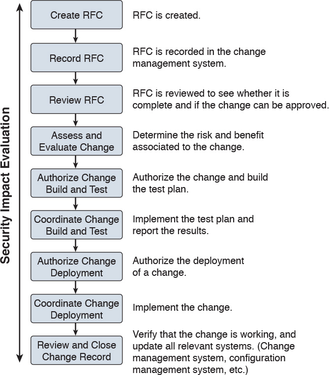
As a security professional, an important step to perform is the security impact analysis of the change. According to NIST SP 800-128, the change security impact analysis includes the following steps:
Step 1. Understand the change. Develop a high-level view of what the change will look like.
Step 2. Identify vulnerabilities. This step includes looking for information on vulnerabilities from the vendor or other vulnerability information providers. This step might also include performing a security analysis of the code.
Step 3. Assess risks. This step includes identifying possible threats and calculating the impact and likelihood of the threats exploiting the system vulnerabilities identified in the previous step. The risk can be accepted, mitigated with the use of additional countermeasures, or avoided, in which case the change request is rejected.
Step 4. Assess the impact on existing security controls. This includes the evaluation of how the change would impact other security controls. For example, a deployment of new application on a server might require a change to a firewall rule.
Step 5. Plan safeguards and countermeasures. This step deals with any safeguards and countermeasures that need to be put in place to mitigate any risk determined by the change request.
Vulnerability Management
A vulnerability, as defined in Chapter 3, “Security Principles,” is an exploitable weakness in a system or its design. Vulnerability management is the process of identifying, analyzing, prioritizing, and remediating vulnerabilities in software and hardware.
As for the other security operations management process discussed in this chapter, vulnerability management intersects with asset management, risk management, configuration and change management, and patch management. For example, to remediate a vulnerability, a patch should be installed on the system, which requires using the patch management process.
There are several frameworks used to describe the vulnerability management processes. For example, in the white paper, “Vulnerability Management: Tools, Challenges and Best Practices” published by the SANS Institute, a six-steps process is proposed that includes asset inventory, information management, risk assessment, vulnerability assessment, report and remediate, and respond. At its core, vulnerability management includes three main phases, as illustrated in Figure 5-17 and described in detail in the sections that follow.

Vulnerability Identification
One important process that is part of vulnerability management is the identification of a vulnerability. There are several ways to identify vulnerabilities in systems. Security professionals need to be aware of these methods and understand the underlying concepts.
Each vendor may identify vulnerabilities based on its own tracking systems and identifiers. This creates several issues in the vulnerability management process. For example, the same vulnerability might be tracked by several identifiers depending on the specific vendor. This, in turn, increases the chance for security gaps.
Common Vulnerabilities and Exposures (CVE) from MITRE is a dictionary of vulnerabilities and exposures in products and systems. It is an industry-standard method for identifying vulnerabilities. Each vulnerability is identified by a CVE identifier (CVE-ID).
Anyone, including researchers, incident response teams, and vendors can request a CVE identifier upon the discovery and disclosure of a vulnerability. The CVE can be requested from one of several CVE numbering authorities (CNAs), which are the only entities authorized to assign a CVE. Cisco is a CNA and can assign a CVE ID directly upon finding any vulnerability in Cisco products. More information about CVE can be found at https://cve.mitre.org.
Finding Information about a Vulnerability
Several sources provide information about vulnerabilities in software and hardware.
Vendor’s Vulnerability Announcements
Most vendors have a vulnerability disclosure policy that is used to provide information about vulnerabilities found in their products. The announcement, usually called a security advisory, includes information such as the vulnerability identifier (both vendor and CVE-ID), the affected products list, a security impact evaluation, and remediation steps. For example, Cisco publishes information about security vulnerabilities on a publicly accessible website. The vendor security vulnerabilities policy will also describe under which condition the vendor will release information, any specific schedule, and other important information about vulnerabilities announcements. The Cisco Security Vulnerability Policy is available via the following URL:
http://www.cisco.com/c/en/us/about/security-center/security-vulnerability-policy.html
Besides providing information on a website, vendors may also provide information via other means (for example, an API) to enable automatic consumption of vulnerability information. Currently, two formats are most commonly used for automatic vulnerability consumption: Open Vulnerability and Assessment Language (OVAL) and Common Vulnerability Reporting Framework (CVRF).
OVAL is an international community standard that promotes open and publicly available security content and standardizes the transfer of this information in security tools and services. It uses a language, the OVAL language, to standardize information such as system configuration, system states (for example, vulnerabilities, patches, and so on), and reporting. It includes three schemas:
![]() OVAL systems characteristic: Used for representing system information
OVAL systems characteristic: Used for representing system information
![]() OVAL definition: Used to represent the state of a system
OVAL definition: Used to represent the state of a system
![]() OVAL result: Used to represent reporting on the assessment
OVAL result: Used to represent reporting on the assessment
OVAL definitions are XML files that contain information about how to check a system for the presence of vulnerabilities, configuration issues, patches, installed applications, or other characteristics. For vulnerability checks, definitions are written to check for a vulnerability identified by a specific CVE identifier.
There are four main use cases, also called “classes,” of OVAL definitions:
![]() Vulnerability: This class determines the presence of a vulnerability on the system being tested
Vulnerability: This class determines the presence of a vulnerability on the system being tested
![]() Compliance: This class validates a device configuration against a known or approved valid configuration
Compliance: This class validates a device configuration against a known or approved valid configuration
![]() Inventory: This class checks for specific software installed on the system
Inventory: This class checks for specific software installed on the system
![]() Patches: This class finds a specific patch on the system
Patches: This class finds a specific patch on the system
Cisco provides an OVAL definition to enable vulnerability information consumption for certain products. More information about OVAL can be found at https://oval.mitre.org/. The following white paper provides an overview on how to use OVAL for security vulnerability automation:
http://www.cisco.com/c/en/us/about/security-center/oval-security-automation.html
Common Vulnerability Reporting Framework (CVRF) from ICASI is an XML-based standard that enables security professionals and organizations to share security vulnerability information in a single format, speeding up information exchange and digestion. Cisco has been a major contributor to this standard. CVRF is a common and consistent framework for exchanging not just vulnerability information, but any security-related documentation. The CVRF section of the XML schema is built following a mind map approach with sections that are set as mandatory and optional. More information about CVRF are available at https://cvrf.github.io/. Cisco publishes security advisories in CVRF format as well. They are available here:
https://tools.cisco.com/security/center/cvrfListing.x
Besides providing information in common standard format, some vendors may provide APIs for direct consumption of vulnerability information. Cisco provides an API for vulnerability through the Cisco PSIRT openVuln program. The Cisco PSIRT openVuln API is a RESTful API that allows customers to obtain Cisco security vulnerability information in different machine-consumable formats. It supports industry-wide security standards such as CVRF and OVAL. This API allows technical staff and programmers to build tools that help them do their jobs more effectively. In this case, it enables them to easily keep up with security vulnerability information specific to their networks.
Vulnerabilities Information Repositories and Aggregators
Following up on vulnerability disclosures and security advisories on vendor websites or via APIs is not a trivial task, especially in a highly heterogeneous and multivendor environment. Security professionals can opt to use vulnerability aggregator services and public vulnerability repositories to find information about vulnerabilities in products.
Here are some public vulnerability information repositories:
![]() cve.mitre.org: Includes a repository of CVE IDs and the descriptions associated with them.
cve.mitre.org: Includes a repository of CVE IDs and the descriptions associated with them.
![]() nvd.nist.gov: The U.S. national vulnerability database is maintained by the NIST. It provides a search engine for CVE and detailed vulnerability information, including vulnerability assessments via Common Vulnerability Scoring System (CVSS; more on CVSS later in this section) and an external reference to the vendor announcement.
nvd.nist.gov: The U.S. national vulnerability database is maintained by the NIST. It provides a search engine for CVE and detailed vulnerability information, including vulnerability assessments via Common Vulnerability Scoring System (CVSS; more on CVSS later in this section) and an external reference to the vendor announcement.
![]() us-cert.gov: Maintained by the U.S. Computer Emergency Readiness Team (CERT). Provides a weekly summary in the form of a bulletin for all vulnerabilities disclosed during the period covered.
us-cert.gov: Maintained by the U.S. Computer Emergency Readiness Team (CERT). Provides a weekly summary in the form of a bulletin for all vulnerabilities disclosed during the period covered.
![]() cert.europa.eu: Maintained by the European CERT (CERT-EU). Provides security advisories to various European institutions and aggregates vulnerability information per vendor base.
cert.europa.eu: Maintained by the European CERT (CERT-EU). Provides security advisories to various European institutions and aggregates vulnerability information per vendor base.
![]() jpcert.or.jp: Maintained by the Japan Computer Emergency Response Team. Provides alerts and bulletins about vulnerabilities from several vendors.
jpcert.or.jp: Maintained by the Japan Computer Emergency Response Team. Provides alerts and bulletins about vulnerabilities from several vendors.
![]() auscert.org.au: The Australian Cyber Emergency Response Team provides security bulletins organized by operating system/environment.
auscert.org.au: The Australian Cyber Emergency Response Team provides security bulletins organized by operating system/environment.
This list is not exhaustive. In most cases, national CERTs also provide relevant vulnerabilities information organized per vendor. Many consultant firms also offer vulnerability aggregator and advisory services that can be customized to provide information only on devices and systems present in the customer environment. Information about vulnerabilities can also be found on security-focused mailing lists. Full Disclosure and Bugtraq are two examples of this type of mailing list.
Vulnerability Scan
Another popular method for identifying vulnerabilities in systems and devices is through a vulnerability scan. A vulnerability scanner is software that can be used to identify vulnerabilities on a system. The scan can be done in two ways:
![]() Active scanner: Sends probes to the system and evaluates a vulnerability based on the system response. An active scanner can be used together with some type of system credentials or without them.
Active scanner: Sends probes to the system and evaluates a vulnerability based on the system response. An active scanner can be used together with some type of system credentials or without them.
![]() Passive scanner: Deployed on the network, a passive scanner observes network traffic generated by a system and determines whether or not the system may be affected by a specific vulnerability.
Passive scanner: Deployed on the network, a passive scanner observes network traffic generated by a system and determines whether or not the system may be affected by a specific vulnerability.
Generally speaking, a vulnerability scanner will not try to exploit a vulnerability but rather base its response on information gathered from the system. For example, a scanner may conclude that a system is affected by a vulnerability because the system banner shows an operating system version that is reported vulnerable by the vendor. However, vulnerability scanners might usually not be able to specify whether that vulnerability can be actually exploited. This, however, largely depends on the scanner capabilities.
Vulnerability scanners usually report on known vulnerabilities with already assigned CVE IDs and are not used to find unknown vulnerabilities in the system. Most modern scanning tools, however, integrate part of the functionality.
Scanners can also be classified as network vulnerability scanners and web vulnerability scanners. Network vulnerability scanners focus on network infrastructure devices and probe the network stack of the target system. Web vulnerability scanners, on the other hand, work at the application level and probe the web services of a target system.
The workflow followed by most security practitioners using vulnerability scanners is as follows:
Step 1. Identify the set of systems that are the targets of the vulnerability scan. The systems are identified either by their IP address or DNS name.
Step 2. Alert the system owners, users, and any other stakeholders of the system. Although vulnerability scanners usually do not cause downtime, it is good practice to run scanners during a maintenance window.
Step 3. Run the scanner.
Step 4. Perform the report analysis.
Vulnerability scanners have become very popular both as part of vulnerability management and as tools for compliance and assurance fulfillment. For example, PCI DSS requires you to perform regular internal and external vulnerability scans. There are several commercial vulnerability scanner tools. Popular commercial vulnerability scanners include the following:
![]() Nessus from Tenable
Nessus from Tenable
![]() Retina from Beyond Trust
Retina from Beyond Trust
![]() Nexpose from Rapid7
Nexpose from Rapid7
![]() AppScan from IBM
AppScan from IBM
![]() AVDS from Beyond Security
AVDS from Beyond Security
Penetration Assessment
A penetration assessment or pen test goes one step further and is used to test an exploit of a vulnerability. Besides trying to exploit known vulnerabilities, penetration tests also can find unknown vulnerabilities in a system. Penetration assessment may also make use of vulnerability scanners to get a list of vulnerabilities that can be used to exploit the system.
A pen test requires advanced skills to be performed properly, and it requires a mixture of automatic and manual tools, especially to find unknown security gaps. Sometimes pen testing is referred to as ethical hacking, and the people performing a pen test are called white hats.
Pen testers try to exploit a single vulnerability or get full control of the system by chaining multiple vulnerabilities, security gaps, and misconfigurations. Vulnerability chaining is the process of exploiting vulnerabilities in sequence so that the exploit of the first vulnerability enables the possible exploitation of a second vulnerability. There are several types of penetration assessments. A popular classification is based on the amount of information received by the pen tester prior to the test:
![]() White box: With this approach, the pen tester has access to inside information and has the possibility to receive documentation about systems, system versions and patch levels, and so on. In some cases, they may also get information on the source code of applications or credentials to access some systems. This approach is generally used to simulate an insider threat.
White box: With this approach, the pen tester has access to inside information and has the possibility to receive documentation about systems, system versions and patch levels, and so on. In some cases, they may also get information on the source code of applications or credentials to access some systems. This approach is generally used to simulate an insider threat.
![]() Black box: This approach is the opposite of white box, and the pen tester does not have any information about the system they are trying to breach. This is more accurate in simulating an external attack. This type of test, however, is less complete than a white box approach because the pen tester needs to find by himself all the information needed in order to prepare the attack. Because these activities are performed during a limited amount of time, not all the security gaps are usually found.
Black box: This approach is the opposite of white box, and the pen tester does not have any information about the system they are trying to breach. This is more accurate in simulating an external attack. This type of test, however, is less complete than a white box approach because the pen tester needs to find by himself all the information needed in order to prepare the attack. Because these activities are performed during a limited amount of time, not all the security gaps are usually found.
![]() Gray box: This is halfway between a white box and a black box approach. In this approach, the pen tester has some information available, but not all.
Gray box: This is halfway between a white box and a black box approach. In this approach, the pen tester has some information available, but not all.
Because penetration assessment can be a very intrusive operation and may cause system outages, or make it completely unavailable, special care should be taken by management and the risk assessment board to make sure the pen test is not disruptive for the business. Usually a compromise needs to be found between performing a realistic test and the risk of affecting normal business operations.
Table 5-7 summarizes the main characteristics of a vulnerability scan and penetration assessment.

Product Vulnerability Management
The vulnerability management process is followed by an organization’s security department and incident response team (IRT) to manage vulnerabilities in products present in the organization’s infrastructure. Product vendors also need a process so that vulnerabilities in products they produce are correctly handled and that information about these vulnerabilities is communicated to affected customers.
The product vulnerability management process is usually handled by the organization Product Security Incident Response Team (PSIRT). This can be a different team than the company’s Computer Security Incident Response Team (CSIRT) or can be integrated with it.
For example, Cisco has PSIRT and CSIRT teams that work on two different aspects of vulnerability management. PSIRT handles the vulnerability management process for vulnerabilities on all Cisco products, whereas CSIRT handles the vulnerability management related to the Cisco IT infrastructure.
The main responsibilities of the PSIRT team are as follows:
![]() Provide a point of contact for vulnerability communication found in Cisco products.
Provide a point of contact for vulnerability communication found in Cisco products.
![]() Provide evaluation, prioritization, and risk information about vulnerabilities.
Provide evaluation, prioritization, and risk information about vulnerabilities.
![]() Help internal stakeholders (for example, product business units) with technical information about vulnerabilities and exploits.
Help internal stakeholders (for example, product business units) with technical information about vulnerabilities and exploits.
![]() Handle external communication of vulnerability information.
Handle external communication of vulnerability information.
According to the Cisco Security Vulnerability Policy, the Cisco PSIRT process includes seven phases:
1. Awareness: PSIRT receives notification of a security incident.
2. Active management: PSIRT prioritizes and identifies resources.
3. Fix determined: PSIRT coordinates a fix and impact assessment.
4. Communication plan: PSIRT sets the timeframe and notification format.
5. Integration and mitigation: PSIRT engages experts and executives.
6. Notification: PSIRT notifies all customers simultaneously.
7. Feedback: PSIRT incorporates feedback from customers and Cisco internal input.
Figure 5-18 shows the Cisco PSIRT process.
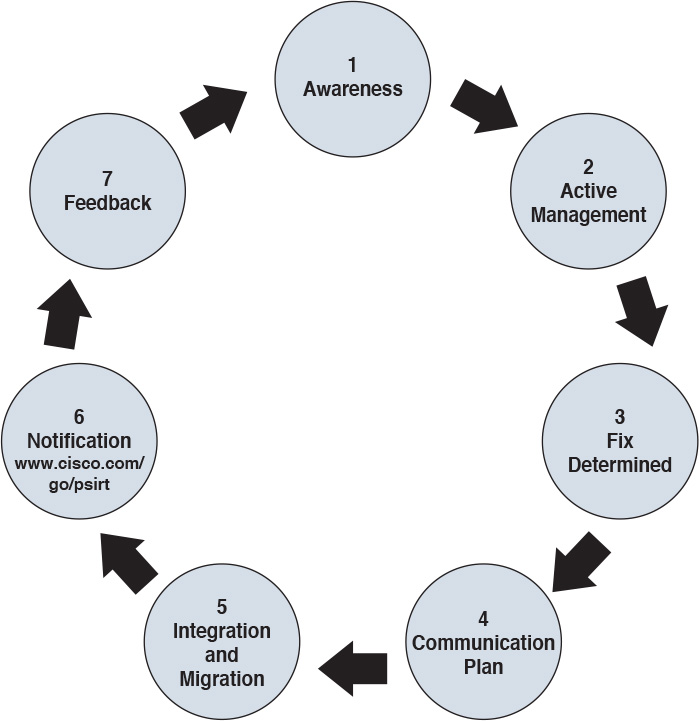
Responsible Disclosure versus Full Disclosure
The disclosure of vulnerability information is one of the most critical tasks of a PSIRT. There are two approaches to vulnerability disclosure. In a full disclosure approach, all the details about a vulnerability are disclosed. While that could help the incident response team to evaluate the vulnerability better and may provide more information for temporary remediation (for example, via network-based mitigation), it usually includes enough details for anyone with the right skill to build exploits. This increases the risk and urgency to implement patches.
In a responsible disclosure approach, relevant information about the vulnerability is disclosed; however, information that could help an attacker to build an exploit is omitted. This provides a good compromise between giving out too much information and allowing a correct analysis from incident response teams and security departments within an organization. Most of the vendors, including Cisco, and national CERTs use a responsible disclosure approach.
Security Content Automation Protocol
Security Content Automation Protocol (SCAP) was created to provide a standardized solution for security automation. The SCAP mission is to maintain system security by ensuring security configuration best practices are implemented in the enterprise network, verifying the presence of patches, and maintaining complete visibility of the security posture of systems and the organization at all times.
The current SCAP specifications include the following:
![]() Languages:
Languages:
![]() Open Vulnerability and Assessment Language (OVAL): OVAL is an international community standard to promote open and publicly available security content and to standardize the transfer of this information in security tools and services. More information about OVAL is available at http://oval.mitre.org.
Open Vulnerability and Assessment Language (OVAL): OVAL is an international community standard to promote open and publicly available security content and to standardize the transfer of this information in security tools and services. More information about OVAL is available at http://oval.mitre.org.
![]() Extensible Configuration Checklist Description Format (XCCDF): XCCDF is a specification for a structured collection of security checklists and benchmarks. More information about XCCDF is available at http://scap.nist.gov/specifications/xccdf.
Extensible Configuration Checklist Description Format (XCCDF): XCCDF is a specification for a structured collection of security checklists and benchmarks. More information about XCCDF is available at http://scap.nist.gov/specifications/xccdf.
![]() Open Checklist Interactive Language (OCIL): OCIL is a framework for collecting and interpreting responses from questions offered to users. More information about OCIL is available at http://scap.nist.gov/specifications/ocil.
Open Checklist Interactive Language (OCIL): OCIL is a framework for collecting and interpreting responses from questions offered to users. More information about OCIL is available at http://scap.nist.gov/specifications/ocil.
![]() Asset Identification (AI): AI is a specification designed to quickly correlate different sets of information about enterprise computing assets. More information about AI is available at http://scap.nist.gov/specifications/ai.
Asset Identification (AI): AI is a specification designed to quickly correlate different sets of information about enterprise computing assets. More information about AI is available at http://scap.nist.gov/specifications/ai.
![]() Asset Reporting Format (ARF): ARF is a specification that defines the transport format of information about enterprise assets and provides a standardized data model to streamline the reporting of such information. More information about ARF is available at http://scap.nist.gov/specifications/arf.
Asset Reporting Format (ARF): ARF is a specification that defines the transport format of information about enterprise assets and provides a standardized data model to streamline the reporting of such information. More information about ARF is available at http://scap.nist.gov/specifications/arf.
Two emerging languages are Asset Summary Reporting (ASR) and the Open Checklist Reporting Language (OCRL). More information about ASR is available at http://scap.nist.gov/specifications/asr/, and more information about OCRL is available at http://ocrl.mitre.org/.
![]() Enumerations:
Enumerations:
![]() Common Vulnerabilities and Exposures (CVE): CVE assigns identifiers to publicly known system vulnerabilities. Cisco assigns CVE identifiers to security vulnerabilities according to the Cisco public vulnerability policy at http://www.cisco.com/web/about/security/psirt/security_vulnerability_policy.html.
Common Vulnerabilities and Exposures (CVE): CVE assigns identifiers to publicly known system vulnerabilities. Cisco assigns CVE identifiers to security vulnerabilities according to the Cisco public vulnerability policy at http://www.cisco.com/web/about/security/psirt/security_vulnerability_policy.html.
More information about CVE is available at http://cve.mitre.org.
![]() Common Platform Enumeration (CPE): CPE is a standardized method of naming and identifying classes of applications, operating systems, and hardware devices. More information about CPE is available at http://nvd.nist.gov/cpe.cfm.
Common Platform Enumeration (CPE): CPE is a standardized method of naming and identifying classes of applications, operating systems, and hardware devices. More information about CPE is available at http://nvd.nist.gov/cpe.cfm.
![]() Common Configuration Enumeration (CCE): CCE provides unique identifiers for configuration guidance documents and best practices. The main goal of CCE is to enable organizations to perform fast and accurate correlation of configuration issues in enterprise systems. More information about CCE is available at http://nvd.nist.gov/cce/index.cfm.
Common Configuration Enumeration (CCE): CCE provides unique identifiers for configuration guidance documents and best practices. The main goal of CCE is to enable organizations to perform fast and accurate correlation of configuration issues in enterprise systems. More information about CCE is available at http://nvd.nist.gov/cce/index.cfm.
NOTE
Other community-developed enumerators, such as the Common Weakness Enumeration (CWE), are currently being expanded and further developed. CWE is a dictionary of common software architecture, design, code, or implementation weaknesses that could lead to security vulnerabilities. More information about CWE is available from http://cwe.mitre.org. Another emerging enumerator is the Common Remediation Enumeration (CRE). More information about CRE is available at http://scap.nist.gov/specifications/cre.
![]() Metrics:
Metrics:
![]() Common Vulnerability Scoring System (CVSS): CVSS is a standards-based scoring method that conveys vulnerability severity and helps determine the urgency and priority of response.
Common Vulnerability Scoring System (CVSS): CVSS is a standards-based scoring method that conveys vulnerability severity and helps determine the urgency and priority of response.
![]() Common Configuration Scoring System (CCSS): More information about CCSS is available in the following PDF document: http://csrc.nist.gov/publications/nistir/ir7502/nistir-7502_CCSS.pdf.
Common Configuration Scoring System (CCSS): More information about CCSS is available in the following PDF document: http://csrc.nist.gov/publications/nistir/ir7502/nistir-7502_CCSS.pdf.
NOTE
Two emerging metrics specifications are the Common Weakness Scoring System (CWSS) and the Common Misuse Scoring System (CMSS). CWSS is a methodology for scoring software weaknesses. CWSS is part of CWE. More information about CWSS is available at http://cwe.mitre.org/cwss. CMSS is a standardized way to measure software feature misuse vulnerabilities. More information about CMSS is available at http://scap.nist.gov/emerging-specs/listing.html#cmss.
![]() Integrity: Provided by the Trust Model for Security Automation Data (TMSAD), which is a trust model for maintaining integrity, authentication, and traceability of security automation data. More information about TMSAD is available in the following PDF document: http://csrc.nist.gov/publications/nistir/ir7802/NISTIR-7802.pdf.
Integrity: Provided by the Trust Model for Security Automation Data (TMSAD), which is a trust model for maintaining integrity, authentication, and traceability of security automation data. More information about TMSAD is available in the following PDF document: http://csrc.nist.gov/publications/nistir/ir7802/NISTIR-7802.pdf.
Figure 5-19 summarizes the SCAP components.

Vulnerability Analysis and Prioritization
Once vulnerabilities are identified on a system, the organization needs to perform an analysis and assign a priority based on the impact on the business. The analysis of a reported vulnerability is aimed at confirming that the system is vulnerable and trying to better understand the characteristics of the vulnerability (for example, the technical details around the trigger and the impact).
Vulnerability analysis typically includes the following tasks:
![]() Determining whether the vulnerability applies to the system based on the actual configuration
Determining whether the vulnerability applies to the system based on the actual configuration
![]() Removing any false positives
Removing any false positives
![]() Contacting the product vendor for additional information
Contacting the product vendor for additional information
![]() Reproducing the vulnerability in-house
Reproducing the vulnerability in-house
If the vulnerability is confirmed, a vulnerability risk assessment should be done so that remediation actions can be properly prioritized. The risk assessment is done based on the severity of the vulnerability and the criticality of the vulnerable system. For example, a medium severity vulnerability on a mission-critical server may receive the same prioritization as a severe vulnerability on a non-mission-critical system.
How organizations determine the severity of a vulnerability and criticality of a system depends on the organization security policy and asset classification. For example, a typical classification for vulnerability severity is Critical, High, Medium, Low, and it is based on the impact the exploitation of the vulnerability can cause on the confidentiality, integrity, and availability of the system.
Common Vulnerability Scoring System (CVSS) is an industry standard used to convey information about the severity of vulnerabilities. In CVSS, a vulnerability is evaluated under three aspects, and a score is assigned to each of them.
![]() The base group represents the intrinsic characteristics of a vulnerability that are constant over time and do not depend on a user-specific environment. This is the most important information and the only mandatory information to obtain for a vulnerability score.
The base group represents the intrinsic characteristics of a vulnerability that are constant over time and do not depend on a user-specific environment. This is the most important information and the only mandatory information to obtain for a vulnerability score.
![]() The temporal group assesses the vulnerability as it changes over time.
The temporal group assesses the vulnerability as it changes over time.
![]() The environmental group represents the characteristic of a vulnerability taking into account the organization’s environment.
The environmental group represents the characteristic of a vulnerability taking into account the organization’s environment.
The CVSS score is obtained by taking into account the base, temporal, and environmental group information.
The score for the base group is between 0 and 10, where 0 is the least severe and 10 is assigned to highly critical vulnerabilities (for example, for vulnerabilities that could allow an attacker to remotely compromise a system and get full control). Additionally, the score comes in the form of a vector string that identifies each of the components used to make up the score. The formula used to obtain the score takes into account various characteristics of the vulnerability and how the attacker is able to leverage these characteristics. At press time, the latest version of the CVSS framework is version 3 (CVSSv3). CVSSv3 defines several characteristics for the base, temporal, and environmental groups.
The base group defines exploitability metrics that measure how the vulnerability can be exploited, and impact metrics that measure the impact on confidentiality, integrity, and availability. In addition to these two, a metric called scope change (S) is used to convey the impact on systems that are affected by the vulnerability but do not contain vulnerable code.
Exploitability metrics include the following:
![]() Attack Vector (AV): Represents the level of access an attacker needs to have to exploit a vulnerability. It can assume four values:
Attack Vector (AV): Represents the level of access an attacker needs to have to exploit a vulnerability. It can assume four values:
![]() Network (N)
Network (N)
![]() Adjacent (A)
Adjacent (A)
![]() Physical (P)
Physical (P)
![]() Attack Complexity (AC): Represents the conditions beyond the attacker’s control that must exist in order to exploit the vulnerability. The values can be one of the following:
Attack Complexity (AC): Represents the conditions beyond the attacker’s control that must exist in order to exploit the vulnerability. The values can be one of the following:
![]() Low (L)
Low (L)
![]() High (H)
High (H)
![]() Privileges Required (PR): Represents the level of privileges an attacker must have to exploit the vulnerability. The values are as follows:
Privileges Required (PR): Represents the level of privileges an attacker must have to exploit the vulnerability. The values are as follows:
![]() None (N)
None (N)
![]() Low (L)
Low (L)
![]() High (H)
High (H)
![]() User Interaction (UI): Captures whether user interaction is needed to perform an attack. The values are as follows:
User Interaction (UI): Captures whether user interaction is needed to perform an attack. The values are as follows:
![]() None (N)
None (N)
![]() Required (R)
Required (R)
![]() Scope (S): Captures the impact on other systems other than the system being scored. The values are as follows:
Scope (S): Captures the impact on other systems other than the system being scored. The values are as follows:
![]() Unchanged (U)
Unchanged (U)
![]() Changed (C)
Changed (C)
The Impact metrics include the following:
![]() Confidentiality Impact (C): Measures the degree of impact to the confidentiality of the system. It can assume the following values:
Confidentiality Impact (C): Measures the degree of impact to the confidentiality of the system. It can assume the following values:
![]() Low (L)
Low (L)
![]() Medium (M)
Medium (M)
![]() High (H)
High (H)
![]() Integrity Impact (I): Measures the degree of impact to the integrity of the system. It can assume the following values:
Integrity Impact (I): Measures the degree of impact to the integrity of the system. It can assume the following values:
![]() Low (L)
Low (L)
![]() Medium (M)
Medium (M)
![]() High (H)
High (H)
![]() Availability Impact (A): Measures the degree of impact to the availability of the system. It can assume the following values:
Availability Impact (A): Measures the degree of impact to the availability of the system. It can assume the following values:
![]() Low (L)
Low (L)
![]() Medium (M)
Medium (M)
![]() High (H)
High (H)
The temporal group includes three metrics:
![]() Exploit code maturity (E): Measures whether or not public exploits are available.
Exploit code maturity (E): Measures whether or not public exploits are available.
![]() Remediation Level (RL): Indicates whether a fix or workaround is available.
Remediation Level (RL): Indicates whether a fix or workaround is available.
![]() Report Confidence (RC): Indicates the degree of confidence in the existence of the vulnerability.
Report Confidence (RC): Indicates the degree of confidence in the existence of the vulnerability.
The environmental group includes two main metrics:
![]() Security Requirements (CR, IR, AR): Indicate the importance of confidentiality, integrity, and availability requirements for the system.
Security Requirements (CR, IR, AR): Indicate the importance of confidentiality, integrity, and availability requirements for the system.
![]() Modified Base Metrics (MAV, MAC, MAPR, MUI, MS, MC, MI, MA): Allow the organization to tweak the base metrics based on specific characteristics of the environment.
Modified Base Metrics (MAV, MAC, MAPR, MUI, MS, MC, MI, MA): Allow the organization to tweak the base metrics based on specific characteristics of the environment.
For example, a vulnerability that could allow a remote attacker to crash the system by sending crafted IP packets would have the following values for the base metrics:
![]() Access Vector (AV) would be Network because the attacker can be anywhere and can send packets remotely.
Access Vector (AV) would be Network because the attacker can be anywhere and can send packets remotely.
![]() Attack Complexity (AC) would be Low because it is trivial to generate malformed IP packets (for example, via the Scapy tool).
Attack Complexity (AC) would be Low because it is trivial to generate malformed IP packets (for example, via the Scapy tool).
![]() Privilege Required (PR) would be None because no privileges are required by the attacker on the target system.
Privilege Required (PR) would be None because no privileges are required by the attacker on the target system.
![]() User Interaction (UI) would also be None because the attacker does not need to interact with any user of the system in order to carry out the attack.
User Interaction (UI) would also be None because the attacker does not need to interact with any user of the system in order to carry out the attack.
![]() Scope (S) would be Unchanged if the attack does not cause other systems to fail.
Scope (S) would be Unchanged if the attack does not cause other systems to fail.
![]() Confidentiality Impact (C) would be None because the primary impact is on the availability of the system.
Confidentiality Impact (C) would be None because the primary impact is on the availability of the system.
![]() Integrity Impact (I) would be None because the primary impact is on the availability of the system.
Integrity Impact (I) would be None because the primary impact is on the availability of the system.
![]() Availability Impact (A) would be High because the device becomes completely unavailable while crashing and reloading.
Availability Impact (A) would be High because the device becomes completely unavailable while crashing and reloading.
The base score vector for this vulnerability is AV:N/AC:L/PR:N/UI:N/S:U/C:N/I:N/A:H, which results in a quantitative score of 7.5. Additional examples of CVSSv3 scoring are available at the FIRST website https://www.first.org/cvss.
Figure 5-20 summarizes the CVSS base, temporal, and environmental metrics.

CVSSv3 also defines a mapping between a CVSSv3 Base Score quantitative value and a qualitative score. Table 5-8 provides the qualitative-to-quantitative score mapping.
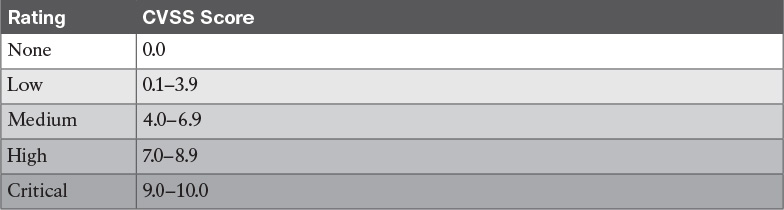
Organizations can use the CVSS score as input to their own risk management processes in order to evaluate the risk related to a vulnerability and then prioritize the vulnerability remediation. Risk management and risk evaluation methods are discussed in Chapter 3.
Vulnerability Remediation
The third phase of vulnerability management is to remediate a vulnerability. The most common way to remediate a vulnerability is by applying a patch or system update that includes the fix for the flaw that caused the vulnerability. Applying a patch or a system update may require extensive testing, organizing the maintenance window, and getting approval for deployment. The process that governs patch and system update deployment is defined within “Patch Management” later in this chapter.
Patching a system may take some time (for example, due to the extensive testing the patch needs to undertake in order to be qualified for production deployment). The risk management board needs to find a compromise between leaving the system unprotected and performing a complete test of the patch. Workarounds and vulnerability mitigations might be used, when available, to temporarily reduce the likelihood or the impact of a vulnerability while the patch goes through the formal patch management process.
A vulnerability workaround is a technical solution that can avoid an exploit of a vulnerability without affecting the service or feature that is affected by the vulnerability itself. For example, creating an access list on a device and dropping a specific malicious packet that triggers the vulnerability is considered a workaround.
Mitigations are technical solutions that limit the exposure or the impact of a vulnerability. Limiting the number of hosts that can send the affected packet via an access control list is an example of a mitigation. It does not eliminate the risk of exploiting a vulnerability, but constrains the attacker’s implementation of the exploit. In this example, the attacker would need to be able to spoof one of the allowed hosts’ IP addresses.
Both workaround and mitigation can be applied on the vulnerable device itself and/or on other systems (for example, on the network infrastructure that provides connectivity to the affected device).
Examples of workarounds and network-based mitigations include the following:
![]() Infrastructure access control lists (iACLs)
Infrastructure access control lists (iACLs)
![]() Transit access control lists (tACLs)
Transit access control lists (tACLs)
![]() Unicast Reverse Path Forwarding (uRPF)
Unicast Reverse Path Forwarding (uRPF)
![]() Layer 2 security (IP Source Guard, Port Security)
Layer 2 security (IP Source Guard, Port Security)
![]() NetFlow
NetFlow
![]() Firewalls (for example, Cisco ASA and Cisco IOS Zone-Based Firewall)
Firewalls (for example, Cisco ASA and Cisco IOS Zone-Based Firewall)
![]() Intrusion prevention systems (for example, FirePower)
Intrusion prevention systems (for example, FirePower)
This list is not exhaustive, and the mitigation largely depends on the vulnerability analysis performed in the previous phase.
Patch Management
Patch management is defined in NIST SP 800-40r3 as the process of identifying, acquiring, installing, and verifying patches for products and systems. In the context security operations management, patch management typically comes as a result of the vulnerabilities remediation phase. As such, patch management sometimes is described as part of vulnerability management. However, the need to install a patch or a system update may span beyond vulnerability remediation (for example, the patch may need to be applied to resolve an operational bug in the software).
Regardless of the reason why a patch needs to be installed, patch management takes care of establishing a process around it. The operational part of the patch process can be considered a case of change management—that is, a request for change (RFC) is raised to request for a system to be patched.
A patch usually fixes a specific software bug or vulnerability, and it is usually applied on top of a software release. A system update refers to a full software package that is installed instead of the existing software release. A system update includes all the patches that have been issued before the update package is created. In some cases, is not possible to provide a point patch; rather, the code needs to be rebuilt with the fix for a specific issue. In that case, the patch will be released with a system upgrade.
Several compliance frameworks require patch management (for example, PCI DSS sets requirements not only about the patch itself but also about the timeframe for installing the patch for vulnerability mitigation).
The patching process includes several steps:
Step 1. Identify the systems. This is where the patch should be installed. A patch may need to be installed, for example, because of a vendor announcement of a new vulnerability, as a result of a vulnerability assessment. Asset inventory and configuration record databases are important to correctly identifying systems that run a version of software that needs to be patched. Other methods for identifying systems are discussed later in this section.
Step 2. Prioritize the systems that need to be patched. Installing a patch or a system update is not a trivial task and requires several resources within the organization. When a new patch is released, it may apply to several systems; however, not all systems may need to be patched immediately. For example, some systems need to be patched immediately because they are mission critical or because they are highly exposed to the vulnerability covered by that patch. Other systems might need to be patched, but there is no immediate danger.
Step 3. Evaluate countermeasures. In some cases, additional compensative controls can be deployed while the patch request goes through the change management process (for example, while the patch is being qualified in the test environment). At the discretion of the system owner and risk profile, a workaround could be deployed instead of a patch, when available.
Step 4. Start the change process. Filing a request for change formally starts the change process to request the installation of a patch. After this point, the process will follow the steps described in the change management process, which includes the following:
![]() Review the RFC.
Review the RFC.
![]() Assess whether the patch deployment needs to follow the formal process.
Assess whether the patch deployment needs to follow the formal process.
![]() Test the patch.
Test the patch.
![]() Perform security impact analysis.
Perform security impact analysis.
![]() Authorize and deploy the patch.
Authorize and deploy the patch.
![]() Verify that the system works correctly.
Verify that the system works correctly.
Testing the patch prior to deployment is one of the most sensitive tasks in the patch management process. Installing a patch could potentially disrupt normal business operation (for example, because of new bugs introduced by the patch). It is very important that the patch is tested in an environment that represents a real business environment. A rollback strategy should also be implemented in case the patch deployment is not done successfully.
Step 5. Update configuration records. Once the patch has been deployed and successfully verified, the configuration record database needs to be updated with the information about the new patch installed and related documentation (such as the time and date for completion, Service Level Agreement [SLA] milestones, issues found during the deployment, and so on).
NOTE
In most of cases, steps 1, 2, and 3 may have already been performed during the vulnerability management process.
Identifying the systems that need to be patched is a complex task; however, it can be greatly simplified by maintaining accurate information in the configuration record database and asset inventory. Enterprise patch management can also help with this task. According to NIST SP 800-40r3, there are three typical deployment models that an enterprise patch management can use:
![]() Agent based: This model uses an agent, which is software installed on the system that communicates with a patch management server. The agent constantly communicates with the server to check whether a new patch is available, and it would retrieve the patch and install it in automatic fashion. The server acts as the patch repository and process orchestrator.
Agent based: This model uses an agent, which is software installed on the system that communicates with a patch management server. The agent constantly communicates with the server to check whether a new patch is available, and it would retrieve the patch and install it in automatic fashion. The server acts as the patch repository and process orchestrator.
This solution offers better protection compared to the other methods; however, because it requires installation of specific software, it might not be suitable for some deployment or appliances.
![]() Agentless: This model includes one device that constantly scans the infrastructure and determines which host to patch. It usually requires administrative access to the target host to be able to perform the scanning. This is a lighter approach compared to the agent-based model; however, it might not work in situations where the host is not always present in the network (for example, mobile devices and laptops).
Agentless: This model includes one device that constantly scans the infrastructure and determines which host to patch. It usually requires administrative access to the target host to be able to perform the scanning. This is a lighter approach compared to the agent-based model; however, it might not work in situations where the host is not always present in the network (for example, mobile devices and laptops).
![]() Passive network monitoring: This model uses network traffic monitoring to determine which version of operating system a host is running. This is the least intrusive method but it’s the least reliable as well. Because it does not require any privileges on the system, it is generally used to check systems that are not under control of the organization (for example, visitor systems).
Passive network monitoring: This model uses network traffic monitoring to determine which version of operating system a host is running. This is the least intrusive method but it’s the least reliable as well. Because it does not require any privileges on the system, it is generally used to check systems that are not under control of the organization (for example, visitor systems).
Prioritization is also a critical step due to the finite resource an organization can assign to the patch management process. The prioritization task is strictly bound to the security risk assessment that needs to be done every time a new vulnerability is announced.
The Cisco Risk Vulnerability Response Model provides a step-by-step approach on how to prioritize the patch and system update deployment whenever information about new vulnerabilities are released by Cisco.
Figure 5-21 illustrates the Cisco recommended approach to patch deployment prioritization.

A patch deployment can be done with various approaches:
![]() Update all or phased deployment: The patch can be deployed at once to all systems that require it, or a phased approach can be used based on prioritization and risk assessment.
Update all or phased deployment: The patch can be deployed at once to all systems that require it, or a phased approach can be used based on prioritization and risk assessment.
![]() Pull or push deployment: The patch can be pushed to the system (for example, in enterprise patch management using an agent-based method), or the user can be asked to install a patch.
Pull or push deployment: The patch can be pushed to the system (for example, in enterprise patch management using an agent-based method), or the user can be asked to install a patch.
![]() Manual or automatic deployment: The patch can be pushed and installed automatically, or the user may be asked to choose to install the patch manually or semi-manually (for example, by requesting the user click an Install button).
Manual or automatic deployment: The patch can be pushed and installed automatically, or the user may be asked to choose to install the patch manually or semi-manually (for example, by requesting the user click an Install button).
References and Additional Readings
ITU-T X.500: Information Technology – Open Systems Interconnection – The Directory: Overview of concepts, models and services
ITU-T X.519: Information Technology – Open Systems Interconnection – The Directory: Protocol specifications
NIST Special Publication 800-128: Guide for Security-Focused Configuration Management of Information Systems, http://nvlpubs.nist.gov/nistpubs/Legacy/SP/nistspecialpublication800-128.pdf
NIST Special Publication 800-53 Revision 4: Security and Privacy Controls for Federal Information Systems and Organizations, http://nvlpubs.nist.gov/nistpubs/SpecialPublications/NIST.SP.800-53r4.pdf
NIST Framework for Improving Critical Infrastructure Cybersecurity, http://www.nist.gov/cyberframework/upload/cybersecurity-framework-021214.pdf
Kerberos Protocol Tutorial, http://www.kerberos.org/software/tutorial.html
The Kerberos Network Authentication Service (V5), https://tools.ietf.org/html/rfc4120
OASIS – Assertions and Protocols for the OASIS Security Assertion Markup Language (SAML) V2.0, http://docs.oasis-open.org/security/saml/v2.0/saml-core-2.0-os.pdf
OASIS – Glossary for the OASIS Security Assertion Markup Language (SAML) V2.0, http://docs.oasis-open.org/security/saml/v2.0/saml-glossary-2.0-os.pdf
OASIS – Security Assertion Markup Language (SAML) V2.0 Technical Overview, http://docs.oasis-open.org/security/saml/Post2.0/sstc-saml-tech-overview-2.0.html
An Introduction to OAuth 2, https://www.digitalocean.com/community/tutorials/an-introduction-to-oauth-2
OpenID Connect Explained, http://connect2id.com/learn/openid-connect
The OAuth 2.0 Authorization Framework, https://tools.ietf.org/html/rfc6749
OpenID Connect Core 1.0 incorporating errata set 1, http://openid.net/specs/openid-connect-core-1_0.html
OpenID Connect, http://openid.net/connect/
OpenID Authentication 2.0 – Final, https://openid.net/specs/openid-authentication-2_0.html
Federated Identities: OpenID vs SAML vs OAuth, https://softwaresecured.com/federated-identities-openid-vs-saml-vs-oauth/
INTERNATIONAL STANDARD ISO/IEC 27001 – Information technology – Security techniques – Information security management systems – Requirements
Gupta, Das Smith, and Sharman, Digital Identity and Access Management, IGI Global (2011)
Cisco Security Information Event Management Deployment Guide, http://www.cisco.com/c/dam/en/us/solutions/collateral/enterprise/design-zone-security-technology-partners/bn_cisco_siem.pdf
NIST SPECIAL PUBLICATION 1800-5b – IT ASSET MANAGEMENT – Approach, Architecture, and Security Characteristics, https://nccoe.nist.gov/sites/default/files/library/sp1800/fs-itam-nist-sp1800-5b-draft.pdf
INTERNATIONAL STANDARD ISO/IEC 27002 – Information technology – Security techniques – Code of practice for information security controls
INTERNATIONAL STANDARD ISO/IEC 27005 Information technology – Security techniques – Information security risk management
Rance, Key Element Guide ITIL Service Transition, Stationery Office (2012)
Risk Triage for Security Vulnerability Announcements, http://www.cisco.com/c/en/us/about/security-center/vulnerability-risk-triage.html
NIST Special Publication 800-40 Revision 3 – Guide to Enterprise Patch Management Technologies, http://nvlpubs.nist.gov/nistpubs/SpecialPublications/NIST.SP.800-40r3.pdf
SANS Institute, “Three Different Shades of Ethical Hacking: Black, White and Gray,” https://www.sans.org/reading-room/whitepapers/hackers/shades-ethical-hacking-black-white-gray-1390
Gatford, Gold, and Manzuik, Network Security Assessment: From Vulnerability to Patch, Singress (2006)
What is the Open Vulnerability and Assessment Language (OVAL)?, https://communities.cisco.com/docs/DOC-63158
I Can’t Keep Up with All These Cisco Security Advisories: Do I Have to Upgrade?, http://blogs.cisco.com/security/i-cant-keep-up-with-all-these-cisco-security-advisories-do-i-have-to-upgrade
Common Vulnerability Scoring System v3.0: User Guide, https://www.first.org/cvss/cvss-v30-user_guide_v1.1.pdf
Cisco Security Vulnerability Policy, http://www.cisco.com/c/en/us/about/security-center/security-vulnerability-policy.html
Introducing the Cisco PSIRT openVuln API, http://blogs.cisco.com/security/psirt-openvuln-api
Help! I Need to Respond to All These Cisco IOS Software Vulnerabilities and I Cannot Scale!!!, http://blogs.cisco.com/security/help-i-need-to-respond-to-all-these-cisco-ios-software-vulnerabilities-and-i-cannot-scale
Cisco Unified Access (UA) and Bring Your Own Device (BYOD) CVD, http://www.cisco.com/c/en/us/td/docs/solutions/Enterprise/Borderless_Networks/Unified_Access/BYOD_Design_Guide/BYOD_MDMs.html
Stuppi and Santos, CCNA Security 210-260 Official Cert Guide, Cisco Press (2015)
NIST Special Publication 800-124 Revision 1, http://nvlpubs.nist.gov/nistpubs/SpecialPublications/NIST.SP.800-124r1.pdf
Enterprise Deployment Guide and Best Practices, https://documentation.meraki.com/SM/Deployment_Guides/Enterprise_Deployment_Guide_and_Best_Practices
Solutions: Mobile device management, https://meraki.cisco.com/solutions/mobile-device-management
Cisco Identity Services Engine Administrator Guide, Release 2.0, http://www.cisco.com/c/en/us/td/docs/security/ise/2-0/admin_guide/b_ise_admin_guide_20/b_ise_admin_guide_20_chapter_01000.html#ID397
NIST Special Publication 800-92 – Guide to Computer Security Log Management, http://csrc.nist.gov/publications/nistpubs/800-92/SP800-92.pdf
The Syslog Protocol, https://tools.ietf.org/html/rfc5424
NIST Special Publication 800-61 Revision 2, http://nvlpubs.nist.gov/nistpubs/SpecialPublications/NIST.SP.800-61r2.pdf
Vulnerability Management: Tools, Challenges and Best Practices - SANS Institute Infosec Reading Room - https://www.sans.org/reading-room/whitepapers/threats/vulnerability-management-tools-challenges-practices-1267
Exam Preparation Tasks
Review All Key Topics
Review the most important topics in the chapter, noted with the Key Topic icon in the outer margin of the page. Table 5-9 lists these key topics and the page numbers on which each is found.
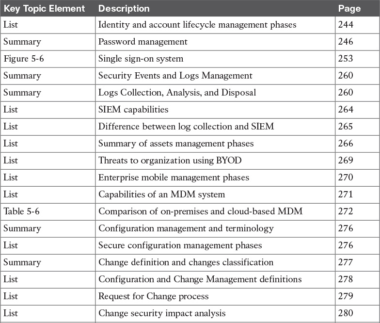

Complete Tables and Lists from Memory
Print a copy of Appendix B, “Memory Tables,” (found on the book website), or at least the section for this chapter, and complete the tables and lists from memory. Appendix C, “Memory Tables Answer Key,” also on the website, includes completed tables and lists to check your work.
Define Key Terms
Define the following key terms from this chapter, and check your answers in the glossary:
identity and access management (IAM)
password management
one-time password
directory
single sign-on (SSO)
Security Information and Event Manager (SIEM)
asset
asset inventory
asset ownership
asset classification
asset handling
enterprise mobile management
mobile device management (MDM)
configuration management
configuration record
configuration management database
security baseline configuration
change management
Common Vulnerabilities and Exposures (CVE)
vulnerability scanner
penetration assessment
Common Vulnerability Scoring System (CVSS)
patch management
Q&A
The answers to these questions appear in Appendix A, “Answers to the ‘Do I Know This Already?’ Quizzes and Q&A Questions.” For more practice with exam format questions, use the exam engine on the website.
1. Which of the following are properties of a secure digital identity? (Select all that apply.)
a. Unique
b. Nondescriptive
c. Encrypted
d. Nominative
2. Why is a periodic access rights and privileges review important?
a. To avoid privilege creep
b. To verify a user’s security clearance
c. To ensure credentials are encrypted
d. To assign a security label
3. In which cases can access be revoked? (Select all that apply.)
a. After job termination
b. When a user moves to another job
c. When creating an administrative user
d. Due to a security violation
4. Which of the following are responsibilities of an asset owner? (Mark all that apply)
a. Implementation of security controls
b. Asset security classification
c. Asset disposal
d. Analysis of the access logs
5. What is the relative distinguished name at the organizational unit level of the following entity? C=US, O=Cisco, OU=CCNA Learning, CN=Jones?
a. OU=CCNA Learning
b. C=US, O=Cisco, OU=CCNA Learning
c. CN=Jones
d. OU=CCNA Learning, CN=Jones
6. In which case should an employee return his laptop to the organization?
a. When moving to a different role
b. Upon termination of the employment
c. As described in the asset return policy
d. When the laptop is end of lease
7. Where are configuration records stored?
a. In a CMDB
b. In a MySQL DB
c. In a XLS file
d. There is no need to store them
8. Which type of vulnerability scanner probes the target system to get information?
a. Intrusive
b. Direct
c. Passive
d. Active
9. In which enterprise patch management model can the system can install a patch automatically?
a. Agentless
b. Passive
c. Agent based
d. Install based
10. What is the syslog priority (PRI) of a message from facility 20 with a severity of 4?
a. 164
b. 160
c. 24
d. 52
11. What is the log normalization functionality used for?
a. It provides a way to archive logs.
b. It aggregates information based on common information and reduces duplicates.
c. It provides reporting capabilities.
d. It extracts relevant attributes from logs received in different formats and stores them in a common data model or template.
12. Which of the following functions are typically provided by an SIEM? (Select all that apply.)
a. Log correlation
b. Log archiving
c. Log normalization
d. Log correction
13. Which elements are found in a typical Cisco BYOD architecture? (Select all that apply.)
a. Mobile device management (MDM) server
b. Cisco ISE
c. Cisco MARS
d. Cisco ASR5000
14. At which step of the change process is the configuration database updated?
a. In the review and close change record
b. When the request for change is created
c. During the change implementation
d. During the request for change review
15. Which of the following are true statements regarding vulnerability scanners and penetration assessments? (Select all that apply.)
a. Vulnerability scanners can crash a device; penetration assessments do not.
b. Vulnerability scanners usually work with known vulnerabilities.
c. Penetration assessment is typically fully automated.
d. Vulnerability scanners can work in active mode and passive mode.
16. What is an OVAL definition?
a. An XML file that contains information about how to check a system for the presence of vulnerabilities.
b. It is synonymous with the OVAL language.
c. An XML file used to represent reporting on the vulnerability assessment.