
Chapter 2. Network Security Devices and Cloud Services
This chapter covers the following topics:
![]() The different network security systems used in today’s environments
The different network security systems used in today’s environments
![]() What the benefits of security cloud-based solutions are and how they work
What the benefits of security cloud-based solutions are and how they work
![]() Details about Cisco NetFlow and how it plays a great role in cyber security
Details about Cisco NetFlow and how it plays a great role in cyber security
![]() Data loss prevention systems and solutions
Data loss prevention systems and solutions
Welcome to the second chapter! In this chapter, you will learn the different types of network security devices and cloud services in the industry. This chapter compares traditional and Next-Generation Firewalls, as well as traditional and Next-Generation Intrusion Prevention Systems (IPS). You will learn details about the Cisco Web Security and Cisco Email Security solutions, as well as what is Advanced Malware Protection (AMP), what are identity management systems, Cisco NetFlow, and details about data loss prevention (DLP).
“Do I Know This Already?” Quiz
The “Do I Know This Already?” quiz helps you identify your strengths and deficiencies in this chapter’s topics. The ten-question quiz, derived from the major sections in the “Foundation Topics” portion of the chapter, helps you determine how to spend your limited study time. You can find the answers in Appendix A Answers to the “Do I Know This Already?” Quizzes and Q&A Questions.
Table 2-1 outlines the major topics discussed in this chapter and the “Do I Know This Already?” quiz questions that correspond to those topics.

1. Which of the following are examples of network security devices that have been invented throughout the years to enforce policy and maintain network visibility?
a. Routers
b. Firewalls
c. Traditional and next-generation intrusion prevention systems (IPSs)
d. Anomaly detection systems
e. Cisco Prime Infrastructure
2. Access control entries (ACE), which are part of an access control list (ACL), can classify packets by inspecting Layer 2 through Layer 4 headers for a number of parameters, including which of the following items?
a. Layer 2 protocol information such as EtherTypes
b. The number of bytes within a packet payload
c. Layer 3 protocol information such as ICMP, TCP, or UDP
d. The size of a packet traversing the network infrastructure device
e. Layer 3 header information such as source and destination IP addresses
f. Layer 4 header information such as source and destination TCP or UDP ports
3. Which of the following statements are true about application proxies?
a. Application proxies, or proxy servers, are devices that operate as intermediary agents on behalf of clients that are on a private or protected network.
b. Clients on the protected network send connection requests to the application proxy to transfer data to the unprotected network or the Internet.
c. Application proxies can be classified as next-generation firewalls.
d. Application proxies always perform network address translation (NAT).
4. Which of the following statements are true when referring to network address translation (NAT)?
a. NAT can only be used in firewalls.
b. Static NAT does not allow connections to be initiated bidirectionally.
c. Static NAT allows connections to be initiated bidirectionally.
d. NAT is often used by firewalls; however, other devices such as routers and wireless access points provide support for NAT.
5. Which of the following are examples of next-generation firewalls?
a. Cisco WSA
b. Cisco ASA 5500-X
c. Cisco ESA
d. Cisco Firepower 4100 Series
6. Which of the following are examples of cloud-based security solutions?
a. Cisco Cloud Threat Security (CTS)
b. Cisco Cloud Email Security (CES)
c. Cisco AMP Threat Grid
d. Cisco Threat Awareness Service (CTAS)
e. OpenDNS
f. CloudLock
7. The Cisco CWS service uses web proxies in the Cisco cloud environment that scan traffic for malware and policy enforcement. Cisco customers can connect to the Cisco CWS service directly by using a proxy auto-configuration (PAC) file in the user endpoint or through connectors integrated into which of the following Cisco products?
a. Cisco ISR G2 routers
b. Cisco Prime LMS
c. Cisco ASA
d. Cisco WSA
e. Cisco AnyConnect Secure Mobility Client
8. Depending on the version of NetFlow, a network infrastructure device can gather different types of information, including which of the following?
a. Common vulnerability enumerators (CVEs)
b. Differentiated services code point (DSCP)
c. The device’s input interface
d. TCP flags
e. Type of service (ToS) byte
9. There are several differences between NetFlow and full-packet capture. Which of the following statements are true?
a. Full-packet capture provides the same information as NetFlow.
b. Full-packet capture is faster.
c. One of the major differences and disadvantages of full-packet capture is cost and the amount of data to be analyzed.
d. In many scenarios, full-packet captures are easier to collect and require pretty much the same analysis ecosystem as NetFlow.
10. Which of the following is an example of a data loss prevention solution?
a. Cisco Advanced DLP
b. Cisco CloudLock
c. Cisco Advanced Malware Protection (AMP)
d. Cisco Firepower 4100 appliances
Foundation Topics
Network Security Systems
Many network security devices have been invented throughout the years to enforce policy and maintain visibility of everything that is happening in the network. These network security devices include the following:
![]() Traditional and next-generation firewalls
Traditional and next-generation firewalls
![]() Personal firewalls
Personal firewalls
![]() Intrusion detection systems (IDSs)
Intrusion detection systems (IDSs)
![]() Traditional and next-generation intrusion prevention systems (IPSs)
Traditional and next-generation intrusion prevention systems (IPSs)
![]() Anomaly detection systems
Anomaly detection systems
![]() Advanced malware protection (AMP)
Advanced malware protection (AMP)
![]() Web security appliances
Web security appliances
![]() Email security appliances
Email security appliances
![]() Identity management systems
Identity management systems
In the following sections, you will learn details about each of the aforementioned network security systems.
Traditional Firewalls
Typically, firewalls are devices that are placed between a trusted and an untrusted network, as illustrated in Figure 2-1.

In Figure 2-1, a firewall is deployed between two networks: a trusted network and an untrusted network. The trusted network is labeled as the “inside” network, and the untrusted network is labeled as the “outside” network. The untrusted network in this case is connected to the Internet. This is the typical nomenclature you’ll often see in Cisco and non-Cisco documentation. When firewalls are connected to the Internet, they are often referred to as Internet edge firewalls. A detailed understanding of how firewalls and their related technologies work is extremely important for all network security professionals. This knowledge not only helps you to configure and manage the security of your networks accurately and effectively, but also allows you to gain an understanding of how to enforce policies and achieve network segmentation suitable for your environment.
Several firewall solutions offer user and application policy enforcement in order to supply protection for different types of security threats. These solutions often provide logging capabilities that enable the security administrators to identify, investigate, validate, and mitigate such threats.
Additionally, several software applications can run on a system to protect only that host. These types of applications are known as personal firewalls. This section includes an overview of network firewalls and their related technologies. Later in this chapter, you will learn the details about personal firewalls.
Network-based firewalls provide key features that are used for perimeter security, such as network address translation (NAT), access control lists (ACLs), and application inspection. The primary task of a network firewall is to deny or permit traffic that attempts to enter or leave the network based on explicit preconfigured policies and rules. Firewalls are often deployed in several other parts of the network to provide network segmentation within the corporate infrastructure and also in data centers. The processes used to allow or block traffic may include the following:
![]() Simple packet-filtering techniques
Simple packet-filtering techniques
![]() Application proxies
Application proxies
![]() Network address translation
Network address translation
![]() Stateful inspection firewalls
Stateful inspection firewalls
![]() Next-generation context-aware firewalls
Next-generation context-aware firewalls
Packet-Filtering Techniques
The purpose of packet filters is simply to control access to specific network segments by defining which traffic can pass through them. They usually inspect incoming traffic at the transport layer of the Open System Interconnection (OSI) model. For example, packet filters can analyze Transmission Control Protocol (TCP) or User Datagram Protocol (UDP) packets and compare them against a set of predetermined rules called access control lists (ACLs). They inspect the following elements within a packet:
![]() Source address
Source address
![]() Destination address
Destination address
![]() Source port
Source port
![]() Destination port
Destination port
![]() Protocol
Protocol
ACLs are typically configured in firewalls, but they also can be configured in network infrastructure devices such as routers, switches, wireless access controllers (WLCs), and others.
Each entry of an ACL is referred to as an access control entry (ACE). These ACEs can classify packets by inspecting Layer 2 through Layer 4 headers for a number of parameters, including the following:
![]() Layer 2 protocol information such as EtherTypes
Layer 2 protocol information such as EtherTypes
![]() Layer 3 protocol information such as ICMP, TCP, or UDP
Layer 3 protocol information such as ICMP, TCP, or UDP
![]() Layer 3 header information such as source and destination IP addresses
Layer 3 header information such as source and destination IP addresses
![]() Layer 4 header information such as source and destination TCP or UDP ports
Layer 4 header information such as source and destination TCP or UDP ports
After an ACL has been properly configured, you can apply it to an interface to filter traffic. The firewall or networking device can filter packets in both the inbound and outbound direction on an interface. When an inbound ACL is applied to an interface, the security appliance analyzes packets against the ACEs after receiving them. If a packet is permitted by the ACL, the firewall continues to process the packet and eventually passes the packet out the egress interface.
The big difference between a router ACL and a Cisco ASA (a stateful firewall) ACL is that only the first packet of a flow is subjected by an ACL in the security appliance. After that, the connection is built, and subsequent packets matching that connection are not checked by the ACL. If a packet is denied by the ACL, the security appliance discards the packet and generates a syslog message indicating that such an event has occurred.
If an outbound ACL is applied on an interface, the firewall processes the packets by sending them through the different processes (NAT, QoS, and VPN) and then applies the configured ACEs before transmitting the packets out on the wire. The firewall transmits the packets only if they are allowed to go out by the outbound ACL on that interface. If the packets are denied by any one of the ACEs, the security appliance discards the packets and generates a syslog message indicating that such an event has occurred.
Following are some of the important characteristics of an ACL configured on a Cisco ASA or on a Cisco IOS zone-based firewall:
![]() When a new ACE is added to an existing ACL, it is appended to the end of the ACL.
When a new ACE is added to an existing ACL, it is appended to the end of the ACL.
![]() When a packet enters the firewall, the ACEs are evaluated in sequential order. Hence, the order of an ACE is critical. For example, if you have an ACE that allows all IP traffic to pass through, and then you create another ACE to block all IP traffic, the packets will never be evaluated against the second ACE because all packets will match the first ACE entry.
When a packet enters the firewall, the ACEs are evaluated in sequential order. Hence, the order of an ACE is critical. For example, if you have an ACE that allows all IP traffic to pass through, and then you create another ACE to block all IP traffic, the packets will never be evaluated against the second ACE because all packets will match the first ACE entry.
![]() There is an implicit deny at the end of all ACLs. If a packet is not matched against a configured ACE, it is dropped and a syslog is generated.
There is an implicit deny at the end of all ACLs. If a packet is not matched against a configured ACE, it is dropped and a syslog is generated.
![]() Each interface is assigned a security level. The higher the security level, the more secure. In traditional Cisco ASA firewalls, the security levels go from 0 (less secure) to 100 (more secure). By default, the outside interface is assigned a security level of 0 and the inside interface is assigned a security level of 100. In the Cisco ASA, by default, you do not need to define an ACE to permit traffic from a high-security-level interface to a low-security-level interface. However, if you want to restrict traffic flows from a high-security-level interface to a low-security-level interface, you can define an ACL. If you configure an ACL to a high-security-level interface to a low-security-level interface, it disables the implicit permit from that interface. All traffic is now subject to the entries defined in that ACL.
Each interface is assigned a security level. The higher the security level, the more secure. In traditional Cisco ASA firewalls, the security levels go from 0 (less secure) to 100 (more secure). By default, the outside interface is assigned a security level of 0 and the inside interface is assigned a security level of 100. In the Cisco ASA, by default, you do not need to define an ACE to permit traffic from a high-security-level interface to a low-security-level interface. However, if you want to restrict traffic flows from a high-security-level interface to a low-security-level interface, you can define an ACL. If you configure an ACL to a high-security-level interface to a low-security-level interface, it disables the implicit permit from that interface. All traffic is now subject to the entries defined in that ACL.
![]() Also in the Cisco ASA, an ACL must explicitly permit traffic traversing the security appliance from a lower- to a higher-security-level interface of the firewall. The ACL must be applied to the lower-security-level interface.
Also in the Cisco ASA, an ACL must explicitly permit traffic traversing the security appliance from a lower- to a higher-security-level interface of the firewall. The ACL must be applied to the lower-security-level interface.
![]() The ACLs (Extended or IPv6) must be applied to an interface to filter traffic that is passing through the security appliance.
The ACLs (Extended or IPv6) must be applied to an interface to filter traffic that is passing through the security appliance.
![]() You can bind one extended and one EtherType ACL in each direction of an interface at the same time.
You can bind one extended and one EtherType ACL in each direction of an interface at the same time.
![]() You can apply the same ACL to multiple interfaces. However, this is not considered to be a good security practice because overlapping and redundant security policies can be applied.
You can apply the same ACL to multiple interfaces. However, this is not considered to be a good security practice because overlapping and redundant security policies can be applied.
![]() You can use ACLs to control traffic through the security appliance, as well as to control traffic to the security appliance. The ACLs controlling traffic to the appliance are applied differently than ACLs filtering traffic through the firewall. The ACLs are applied using access groups. The ACL controlling traffic to the security appliance are called controlled plane ACLs.
You can use ACLs to control traffic through the security appliance, as well as to control traffic to the security appliance. The ACLs controlling traffic to the appliance are applied differently than ACLs filtering traffic through the firewall. The ACLs are applied using access groups. The ACL controlling traffic to the security appliance are called controlled plane ACLs.
![]() When TCP or UDP traffic flows through the security appliance, the return traffic is automatically allowed to pass through because the connections are considered established and bidirectional.
When TCP or UDP traffic flows through the security appliance, the return traffic is automatically allowed to pass through because the connections are considered established and bidirectional.
![]() Other protocols such as ICMP are considered unidirectional connections and therefore you need to allow ACL entries in both directions. There is an exception for the ICMP traffic when you enable the ICMP inspection engine.
Other protocols such as ICMP are considered unidirectional connections and therefore you need to allow ACL entries in both directions. There is an exception for the ICMP traffic when you enable the ICMP inspection engine.
The Cisco ASA supports five different types of ACLs to provide a flexible and scalable solution to filter unauthorized packets into the network:
![]() Standard ACLs
Standard ACLs
![]() Extended ACLs
Extended ACLs
![]() IPv6 ACLs
IPv6 ACLs
![]() EtherType ACLs
EtherType ACLs
![]() Webtype ACLs
Webtype ACLs
Standard ACLs
Standard ACLs are used to identify packets based on their destination IP addresses. These ACLs can be used in scenarios such as split tunneling for the remote-access VPN tunnels and route redistribution within route maps for dynamic routing deployments (OSPF, BGP, and so on). These ACLs, however, cannot be applied to an interface for filtering traffic. A standard ACL can be used only if the security appliance is running in routed mode. In routed mode, the Cisco ASA routes packets from one subnet to another subnet by acting as an extra Layer 3 hop in the network.
Extended ACLs
Extended ACLs, the most commonly deployed ACLs, can classify packets based on the following attributes:
![]() Source and destination IP addresses
Source and destination IP addresses
![]() Layer 3 protocols
Layer 3 protocols
![]() Source and/or destination TCP and UDP ports
Source and/or destination TCP and UDP ports
![]() Destination ICMP type for ICMP packets
Destination ICMP type for ICMP packets
An extended ACL can be used for interface packet filtering, QoS packet classification, packet identification for NAT and VPN encryption, and a number of other features. These ACLs can be set up on the Cisco ASA in the routed and the transparent mode.
EtherType ACLs
EtherType ACLs can be used to filter IP and non-IP-based traffic by checking the Ethernet type code field in the Layer 2 header. IP-based traffic uses an Ethernet type code value of 0x800, whereas Novell IPX uses 0x8137 or 0x8138, depending on the Netware version.
An EtherType ACL can be configured only if the security appliance is running in transparent mode. Just like any other ACL, the EtherType ACL has an implicit deny at the end of it. However, this implicit deny does not affect the IP traffic passing through the security appliance. As a result, you can apply both EtherType and extended ACLs to each direction of an interface. If you configure an explicit deny at the end of an EtherType ACL, it blocks IP traffic even if an extended ACL is defined to pass those packets.
Webtype ACLs
A Webtype ACL allows security appliance administrators to restrict traffic coming through the SSL VPN tunnels. In cases where a Webtype ACL is defined but there is no match for a packet, the default behavior is to drop the packet because of the implicit deny. On the other hand, if no ACL is defined, the security appliance allows traffic to pass through it.
An ACL Example
Example 2-1 shows the command-line interface (CLI) configuration of an extended ACL. The ACL is called outside_acl_in, and it is composed of four ACEs. The first two ACEs allow HTTP traffic destined for 10.10.20.111 from the two client machines, whereas the last two ACEs allow SMTP access to 10.10.20.112 from both machines. Adding remarks to an ACL is recommended because it helps others to recognize its function. In Example 2-1 the system administrator has added the ACL remark: “ACL to block inbound traffic except HTTP and SMTP.”
Example 2-1 Configuration Example of an Extended ACL
ASA# configure terminal
ASA(config)# access-list outside_access_in remark ACL to block inbound traffic except
HTTP and SMTP
ASA(config)# access-list outside_access_in extended permit tcp host 10.10.10.1 host
10.10.202.131 eq http
ASA(config)# access-list outside_access_in extended permit tcp host 10.10.10.2 host
209.165.202.131 eq http
ASA(config)# access-list outside_access_in extended permit tcp host 10.10.10.1 host
10.10.20.112 eq smtp
ASA(config)# access-list outside_access_in extended permit tcp host 10.10.10.2 host
10.10.20.112 eq smtp
Always remember that there is an implicit deny at the end of any ACL.
Packet filters do not commonly inspect additional Layer 3 and Layer 4 fields such as sequence numbers, TCP control flags, and TCP acknowledgment (ACK) fields. The firewalls that inspect such fields and flags are referred to as stateful firewalls. You will learn how stateful firewalls operate later in this chapter in the “Stateful Inspection Firewalls” section.
Various packet-filtering firewalls can also inspect packet header information to find out whether the packet is from a new or an existing connection. Simple packet-filtering firewalls have several limitations and weaknesses:
![]() Their ACLs or rules can be relatively large and difficult to manage.
Their ACLs or rules can be relatively large and difficult to manage.
![]() They can be deceived into permitting unauthorized access of spoofed packets. Attackers can orchestrate a packet with an IP address that is authorized by the ACL.
They can be deceived into permitting unauthorized access of spoofed packets. Attackers can orchestrate a packet with an IP address that is authorized by the ACL.
![]() Numerous applications can build multiple connections on arbitrarily negotiated ports. This makes it difficult to determine which ports are selected and used until after the connection is completed. Examples of this type of application are multimedia applications such as streaming audio and video applications. Packet filters do not understand the underlying upper-layer protocols used by this type of application, and providing support for this type of application is difficult because the ACLs need to be manually configured in packet-filtering firewalls.
Numerous applications can build multiple connections on arbitrarily negotiated ports. This makes it difficult to determine which ports are selected and used until after the connection is completed. Examples of this type of application are multimedia applications such as streaming audio and video applications. Packet filters do not understand the underlying upper-layer protocols used by this type of application, and providing support for this type of application is difficult because the ACLs need to be manually configured in packet-filtering firewalls.
Application Proxies
Application proxies, or proxy servers, are devices that operate as intermediary agents on behalf of clients that are on a private or protected network. Clients on the protected network send connection requests to the application proxy to transfer data to the unprotected network or the Internet. Consequently, the application proxy (sometimes referred to as a web proxy) sends the request on behalf of the internal client. The majority of proxy firewalls work at the application layer of the OSI model. Most proxy firewalls can cache information to accelerate their transactions. This is a great tool for networks that have numerous servers that experience high usage. Additionally, proxy firewalls can protect against some web-server-specific attacks; however, in most cases, they do not provide any protection against the web application itself.
Network Address Translation
Several Layer 3 devices can supply network address translation (NAT) services. The Layer 3 device translates the internal host’s private (or real) IP addresses to a publicly routable (or mapped) address.
Cisco uses the terminology of “real” and “mapped” IP addresses when describing NAT. The real IP address is the address that is configured on the host, before it is translated. The mapped IP address is the address to which the real address is translated.
TIP
Static NAT allows connections to be initiated bidirectionally, meaning both to the host and from the host.
Figure 2-2 demonstrates how a host on the inside of a firewall with the private address of 10.10.10.123 is translated to the public address 209.165.200.227.
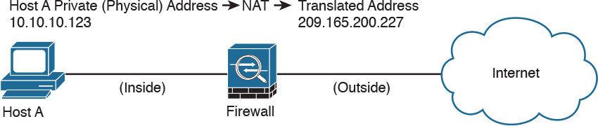
NAT is often used by firewalls; however, other devices such as routers and wireless access points provide support for NAT. By using NAT, the firewall hides the internal private addresses from the unprotected network and exposes only its own address or public range. This enables a network professional to use any IP address space as the internal network. A best practice is to use the address spaces that are reserved for private use (see RFC 1918, “Address Allocation for Private Internets”). Table 1-1 lists the private address ranges specified in RFC 1918.

It is important to think about the different private address spaces when you plan your network (for example, the number of hosts and subnets that can be configured). Careful planning and preparation lead to substantial time savings if changes are encountered down the road.
TIP
The whitepaper titled “A Security-Oriented Approach to IP Addressing” provides numerous tips on planning and preparing your network IP address scheme. You can find this whitepaper here: http://www.cisco.com/web/about/security/intelligence/security-for-ip-addr.html.
Port Address Translation
Typically, firewalls perform a technique called port address translation (PAT). This feature, which is a subset of the NAT feature, allows many devices on the internal protected network to share one IP address by inspecting the Layer 4 information on the packet. This shared address is usually the firewall’s public address; however, it can be configured to any other available public IP address. Figure 2-3 shows how PAT works.

As illustrated in Figure 2-3, several hosts on a trusted network labeled “inside” are configured with an address from the network 10.10.10.0 with a 24-bit subnet mask. The ASA is performing PAT for the internal hosts and translating the 10.10.10.x addresses into its own address (209.165.200.228). In this example, Host A sends a TCP port 80 packet to the web server located in the “outside” unprotected network. The ASA translates the request from the original 10.10.10.8 IP address of Host A to its own address. It does this by randomly selecting a different Layer 4 source port when forwarding the request to the web server. The TCP source port is modified from 1024 to 1188 in this example.
Static Translation
A different methodology is used when hosts in the unprotected network need to initiate a new connection to specific hosts behind the NAT device. You configure the firewall to allow such connections by creating a static one-to-one mapping of the public (mapped) IP address to the address of the internal (real) protected device. For example, static NAT can be configured when a web server resides on the internal network and has a private IP address but needs to be contacted by hosts located in the unprotected network or the Internet. Figure 2-2 demonstrated how static translation works. The host address (10.10.10.123) is statically translated to an address in the outside network (209.165.200.227, in this case). This allows the outside host to initiate a connection to the web server by directing the traffic to 209.165.200.227. The device performing NAT then translates and sends the request to the web server on the inside network.
Firewalls like the Cisco ASA, Firepower Threat Defense (FTD), Cisco IOS zone-based firewalls and others can perform all these NAT operations. On the other hand, address translation is not limited to firewalls. Nowadays, all sorts of lower-end network devices such as simple small office, home office (SOHO) and wireless routers can perform different NAT techniques.
Stateful Inspection Firewalls
Stateful inspection firewalls provide enhanced benefits when compared to simple packet-filtering firewalls. They track every packet passing through their interfaces by ensuring that they are valid, established connections. They examine not only the packet header contents but also the application layer information within the payload. Subsequently, different rules can be created on the firewall to permit or deny traffic based on specific payload patterns. A stateful firewall monitors the state of the connection and maintains a database with this information, usually called the state table. The state of the connection details whether such a connection has been established, closed, reset, or is being negotiated. These mechanisms offer protection for different types of network attacks.
Demilitarized Zones
Firewalls can be configured to separate multiple network segments (or zones), usually called demilitarized zones (DMZs). These zones provide security to the systems that reside within them with different security levels and policies between them. DMZs can have several purposes; for example, they can serve as segments on which a web server farm resides or as extranet connections to a business partner. Figure 2-4 shows a Cisco ASA with a DMZ.
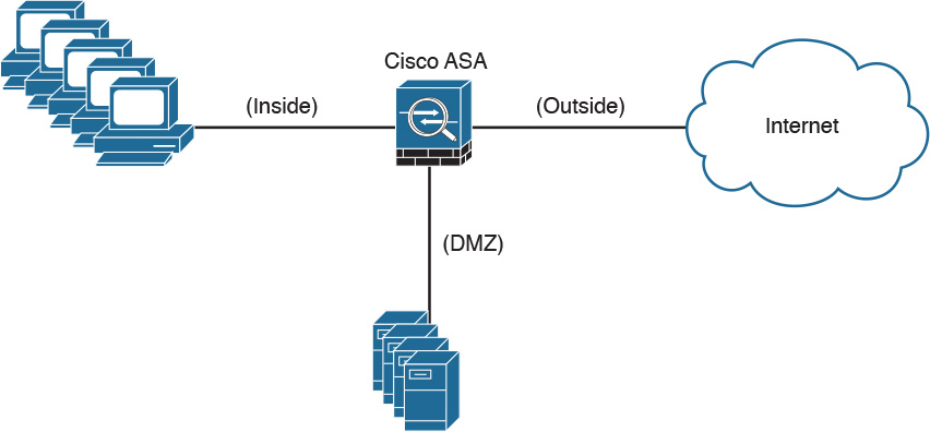
DMZs minimize the exposure of devices and clients on your internal network by allowing only recognized and managed services on those hosts to be accessible from the Internet. In Figure 2-4, the DMZ hosts web servers that are accessible by internal and Internet hosts. In large organizations, you can find multiple firewalls in different segments and DMZs.
Firewalls Provide Network Segmentation
Firewalls can provide network segmentation while enforcing policies between those segments. In Figure 2-5, a firewall is segmenting and enforcing policies between three networks in the overall corporate network. The first network is the finance department, the second is the engineering department, and the third is the sales department.

High Availability
Firewalls such as the Cisco ASA provide high availability features such as the following:
![]() Active-standby failover
Active-standby failover
![]() Active-active failover
Active-active failover
![]() Clustering
Clustering
Active-Standby Failover
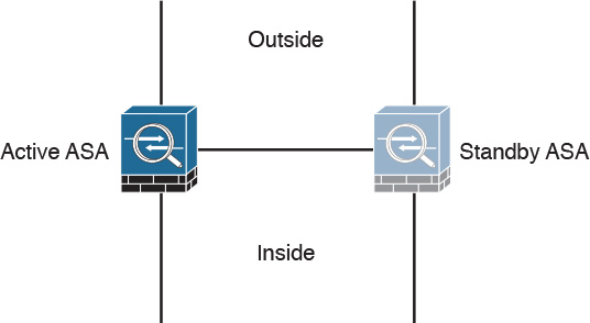
In an active-standby failover configuration, the primary firewall is always active and the secondary is in standby mode. When the primary firewall fails, the secondary firewall takes over. Figure 2-6 shows a pair of Cisco ASA firewalls in an active-standby failover configuration.
The configuration and stateful network information is synchronized from the primary firewall to the secondary.
In an active-active failover configuration, both of the firewalls are active. If one fails, the other will continue to pass traffic in the network. Figure 2-7 shows a pair of Cisco ASA firewalls in an active-active failover configuration.

Clustering Firewalls
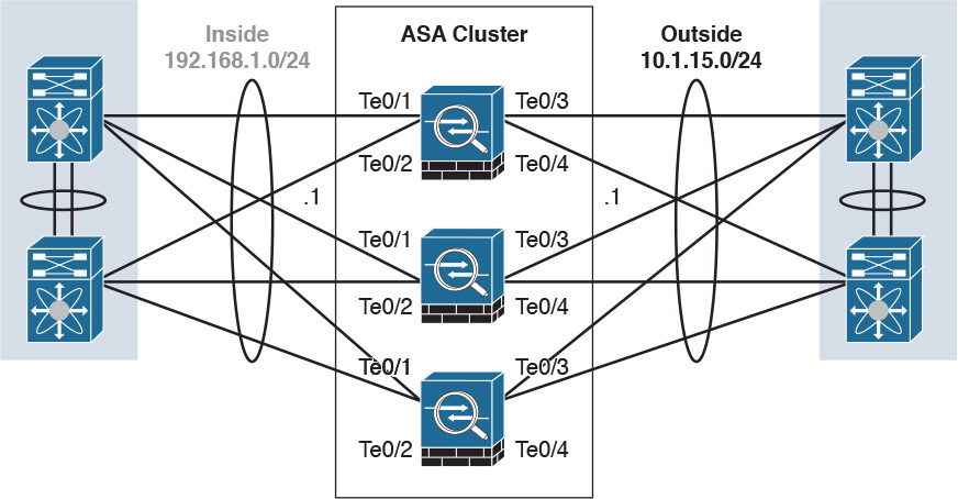
Firewalls such as the Cisco ASA can also be clustered to provide next-generation firewall protection in large and highly scalable environments. For example, the Cisco ASA firewalls can be part of a cluster of up to 16 firewalls. Figure 2-8 shows a cluster of three Cisco ASAs. One of the main reasons to cluster firewalls is to increase packet throughput and to scale in a more efficient way.
In Figure 2-8, the Cisco ASAs have 10 Gigabit Ethernet interfaces in an Etherchannel configuration to switches in both inside and outside networks. An Etherchannel involves bundling together two or more interfaces in order to scale and achieve bigger bandwidth.
Firewalls in the Data Center
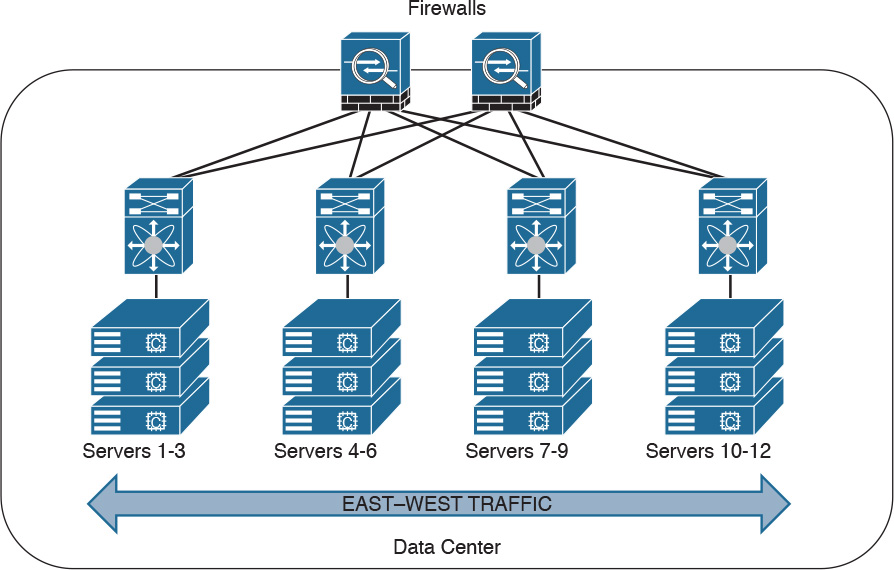
Firewalls can also be deployed in the data center. The placement of firewalls in the data center will depend on many factors, such as how much latency the firewalls will introduce, what type of traffic you want to block and allow, and in what direction the traffic will flow (either north to south or east to west).
In the data center, traffic going from one network segment or application of the data center to another network segment or application within the data center is often referred to as east-to-west (or west-to-east) traffic. This is also known as lateral traffic. Figure 2-9 demonstrates east-west traffic.
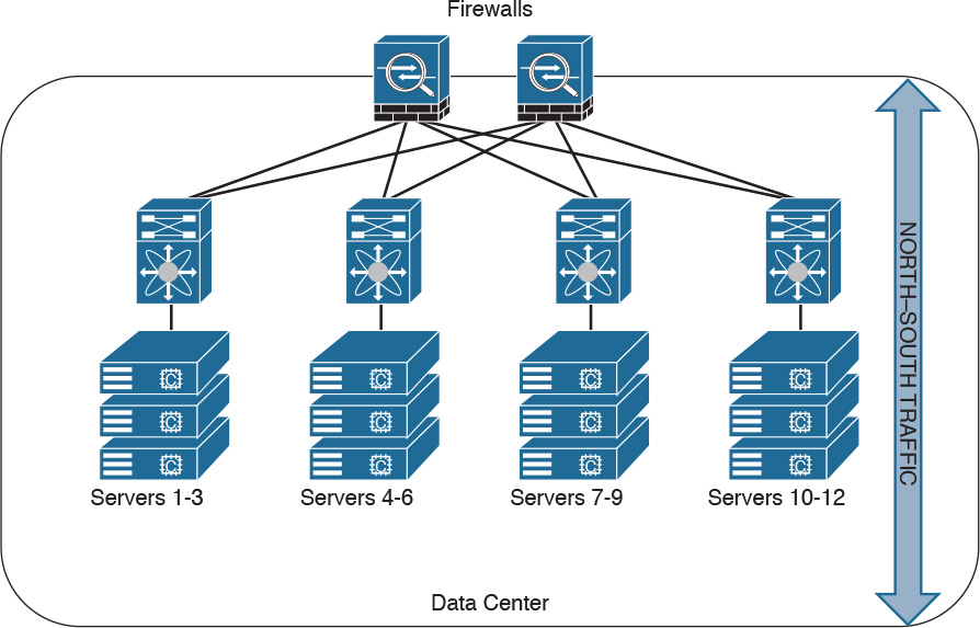
Similarly, traffic going to and from the data center and the rest of the corporate network is often referred to as north-to-south (or south-to-north) traffic. Figure 2-10 demonstrates north-south traffic.
Another example of advanced segmentation and micro-segmentation in the data center is the security capabilities of the Cisco Application Centric Infrastructure (ACI). Cisco ACI is a software-defined networking (SDN) solution that has a very robust policy model across data center networks, servers, storage, security, and services. This policy-based automation helps network administrators to achieve micro-segmentation through the integration of physical and virtual environments under one policy model for networks, servers, storage, services, and security. Even if servers and applications are “network adjacent” (that is, on the same network segment), they will not communicate with each other until a policy is configured and provisioned. This is why Cisco ACI is very attractive to many security-minded network administrators. Another major benefit of Cisco ACI is automation. With such automation, you can reduce application deployment times from weeks to minutes. Cisco ACI policies are enforced and deployed by the Cisco Application Policy Infrastructure Controller (APIC).
Virtual Firewalls
Firewalls can also be deployed as virtual machines (VMs). An example of a virtual firewall is the Cisco ASAv. These virtual firewalls are often deployed in the data center to provide segmentation and network protection to virtual environments. They are typically used because traffic between VMs often does not leave the physical server and cannot be inspected or enforced with physical firewalls.
The Cisco ASA also has a featured called virtual contexts. This is not the same as the virtual firewalls described previously. In the Cisco ASA security context feature, one physical appliance can be “virtualized” into separate contexts (or virtual firewalls). Virtual firewalls such as the Cisco ASAv run on top of VMware or KVM on a physical server such as the Cisco UCS.
Figure 2-11 shows two virtual firewalls providing network segmentation between several VMs deployed in a physical server.

Deep Packet Inspection
Several applications require special handling of data packets when they pass through firewalls. These include applications and protocols that embed IP addressing information in the data payload of the packet or open secondary channels on dynamically assigned ports. Sophisticated firewalls and security appliances such as the Cisco ASA and Cisco IOS Firewall offer application inspection mechanisms to handle the embedded addressing information to allow the previously mentioned applications and protocols to work. Using application inspection, these security appliances can identify the dynamic port assignments and allow data exchange on these ports during a specific connection.
With deep packet inspection, firewalls can look at specific Layer 7 payloads to protect against security threats. For example, you can configure a Cisco ASA running version 7.0 or later to not allow peer-to-peer (P2P) applications to be transferred over the HTTP protocol. You can also configure these devices to deny specific FTP commands, HTTP content types, and other application protocols.
TIP
The Cisco ASA provides a Modular Policy Framework (MPF) that offers a consistent and flexible way to configure application inspection and other features to specific traffic flows in a manner similar to the Cisco IOS Software modular quality-of-service (QoS) command-line interface (CLI).
Next-Generation Firewalls
The proliferation of mobile devices and the need to connect from any place are radically changing the enterprise security landscape. Social networking sites such as Facebook and Twitter long ago moved beyond mere novelty sites for teens and geeks and have become vital channels for communicating with groups and promoting brands.
Security concerns and fear of data loss are leading reasons why some businesses don’t embrace social media, but many others are adopting social media as a vital resource within the organization. Some of the risks associated with social media can be mitigated through the application of technology and user controls. However, there’s no doubt that criminals have used social media networks to lure victims into downloading malware and handing over login passwords.
Before today’s firewalls grant network access, they need to be aware of not only the applications and users accessing the infrastructure but also the device in use, the location of the user, and the time of day. Such context-aware security requires a rethinking of the firewall architecture. Context-aware firewalls extend beyond the next-generation firewalls on the market today. They provide granular control of applications, comprehensive user identification, and location-based control. The Cisco ASA 5500-X Series next-generation firewalls are examples of context-based firewall solutions.
The Cisco ASA family provides a very comprehensive set of features and next-generation security capabilities. For example, it provides capabilities such as simple packet filtering (normally configured with access control lists, or ACLs) and stateful inspection. The Cisco ASA also provides support for application inspection/awareness. It can listen in on conversations between devices on one side and devices on the other side of the firewall. The benefit of listening in is so that the firewall can pay attention to application layer information.
The Cisco ASA also supports network address translation (NAT), the capability to act as a Dynamic Host Configuration Protocol (DHCP) server or client, or both. The Cisco ASA supports most of the interior gateway routing protocols, including Routing Information Protocol (RIP), Enhanced Interior Gateway Routing Protocol (EIGRP), and Open Shortest Path First (OSPF). It also supports static routing. The Cisco ASA also can be implemented as a traditional Layer 3 firewall, which has IP addresses assigned to each of its routable interfaces. The other option is to implement a firewall as a transparent (Layer 2) firewall, in which the actual physical interfaces receive individual IP addresses, but a pair of interfaces operate like a bridge. Traffic that is going across this two-port bridge is still subject to the rules and inspection that can be implemented by the ASA. Additionally, the Cisco ASA is often used as a head-end or remote-end device for VPN tunnels for both remote-access VPN users and site-to-site VPN tunnels. It supports IPsec and SSL-based remote access VPNs. The SSL VPN capabilities include support for clientless SSL VPN and the full AnyConnect SSL VPN tunnels.
Cisco Firepower Threat Defense
The Cisco Firepower Threat Defense (FTD) is unified software that includes Cisco ASA features, legacy FirePOWER Services, and new features. FTD can be deployed on Cisco Firepower 4100 and 9300 appliances to provide next-generation firewall (NGFW) services. In addition to being able to run on the Cisco Firepower 4100 Series and the Firepower 9300 appliances, FTD can also run natively on the ASA 5506-X, ASA 5506H-X, ASA 5506W-X, ASA 5508-X, ASA 5512-X, ASA 5515-X, ASA 5516-X, ASA 5525-X, ASA 5545-X, and ASA 5555-X. It is not supported in the ASA 5505 or the 5585-X. FTD can also run as a virtual machine (Cisco Firepower Threat Defense Virtual, or FTDv).
NOTE
Cisco spells the word FirePOWER (uppercase “POWER”) when referring to the Cisco ASA FirePOWER Services module. The word Firepower (lowercase “power”) is used when referring to all other software, such as FTD, Firepower Management Center (FMC), and Firepower appliances.
Cisco Firepower 4100 Series
The Cisco Firepower 4100 Series appliances are next-generation firewalls that run the Cisco FTD software and features. There are four models:
![]() Cisco Firepower 4110, which supports up to 20 Gbps of firewall throughput
Cisco Firepower 4110, which supports up to 20 Gbps of firewall throughput
![]() Cisco Firepower 4120, which supports up to 40 Gbps of firewall throughput
Cisco Firepower 4120, which supports up to 40 Gbps of firewall throughput
![]() Cisco Firepower 4140, which supports up to 60 Gbps of firewall throughput
Cisco Firepower 4140, which supports up to 60 Gbps of firewall throughput
![]() Cisco Firepower 4150, which supports over 60 Gbps of firewall throughput
Cisco Firepower 4150, which supports over 60 Gbps of firewall throughput
All of the Cisco Firepower 4100 Series models are one rack-unit (1 RU) appliances and are managed by the Cisco Firepower Management Center.
Cisco Firepower 9300 Series
The Cisco Firepower 9300 appliances are designed for very large enterprises or service providers. They can scale beyond 1 Tbps and are designed in a modular way, supporting Cisco ASA software, Cisco FTD software, and Radware DefensePro DDoS mitigation software. Radware DefensePro DDoS mitigation software is provided by Radware, a Cisco partner.
NOTE
The Radware DefensePro DDoS mitigation software is available and supported directly from Cisco on Cisco Firepower 4150 and Cisco Firepower 9300 appliances.
Radware’s DefensePro DDoS mitigation software provides real-time analysis to protect the enterprise or service provider infrastructure against network and application downtime due to distributed denial of service (DDoS) attacks.
Cisco FTD for Cisco Integrated Services Routers (ISRs)
The Cisco FTD can run on Cisco Unified Computing System (UCS) E-Series blades installed on Cisco ISR routers. Both the FMC and FTD are deployed as virtual machines. There are two internal interfaces that connect a router to a UCS E-Series blade. On ISR G2, Slot0 is a Peripheral Component Interconnect Express (PCIe) internal interface, and UCS E-Series Slot1 is a switched interface connected to the backplane Multi Gigabit Fabric (MGF). In Cisco ISR 4000 Series routers, both internal interfaces are connected to the MGF.
A hypervisor is installed on the UCS E-Series blade, and the Cisco FTD software runs as a virtual machine on it. FTD for ISRs is supported on the following platforms:
![]() Cisco ISR G2 Series: 2911, 2921, 2951, 3925, 3945, 3925E, and 3945E
Cisco ISR G2 Series: 2911, 2921, 2951, 3925, 3945, 3925E, and 3945E
![]() Cisco ISR 4000 Series: 4331, 4351, 4451, 4321, and 4431
Cisco ISR 4000 Series: 4331, 4351, 4451, 4321, and 4431
Personal Firewalls
Personal firewalls are popular software applications that you can install on end-user machines or servers to protect them from external security threats and intrusions. The term personal firewall typically applies to basic software that controls Layer 3 and Layer 4 access to client machines. Today, sophisticated software is available that not only supplies basic personal firewall features but also protects the system based on the behavior of the applications installed on such systems.
Intrusion Detection Systems and Intrusion Prevention Systems
Intrusion detection systems (IDSs) are devices that detect (in promiscuous mode) attempts from an attacker to gain unauthorized access to a network or a host, to create performance degradation, or to steal information. They also detect distributed denial-of-service (DDoS) attacks, worms, and virus outbreaks. Figure 2-12 shows how an IDS device is configured to promiscuously detect security threats.

In Figure 2-12, a compromised host sends a malicious packet to a series of hosts in the 10.10.20.0/24 network. The IDS device analyzes the packet and sends an alert to a monitoring system. The malicious packet still successfully arrives at the 10.10.20.0/24 network.
Intrusion prevention system (IPS) devices, on the other hand, are capable of not only detecting all these security threats, but also dropping malicious packets inline. IPS devices may be initially configured in promiscuous mode (monitoring mode) when you are first deploying them in the network. This is done to analyze the impact to the network infrastructure. Then they are deployed in inline mode to be able to block any malicious traffic in your network.
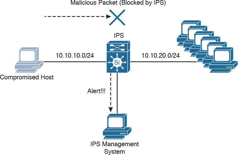
Figure 2-13 shows how an IPS device is placed inline and drops the noncompliant packet while sending an alert to the monitoring system.
A few different types of IPSs exist:
![]() Traditional network-based IPSs (NIPSs)
Traditional network-based IPSs (NIPSs)
![]() Next-generation IPS systems (NGIPSs)
Next-generation IPS systems (NGIPSs)
![]() Host-based IPSs (HIPSs)
Host-based IPSs (HIPSs)
Examples of traditional NIPSs are the Cisco IPS 4200 sensors and the Catalyst 6500 IPS module. These devices have been in the end-of-life (EoL) stage for quite some time. Examples of NGIPSs are the Cisco Firepower IPS systems.
The Cisco ASA 5500 Series FirePOWER Services provide intrusion prevention, firewall, and VPN services in a single, easy-to-deploy platform. Intrusion prevention services enhance firewall protection by looking deeper into the flows to provide protection against threats and vulnerabilities. The Cisco Firepower Threat Defense (FTD) provides these capabilities in a combined software package.
Network-based IDSs and IPSs use several detection methodologies, such as the following:
![]() Pattern matching and stateful pattern-matching recognition
Pattern matching and stateful pattern-matching recognition
![]() Protocol analysis
Protocol analysis
![]() Heuristic-based analysis
Heuristic-based analysis
![]() Anomaly-based analysis
Anomaly-based analysis
![]() Global threat correlation capabilities
Global threat correlation capabilities
Pattern Matching and Stateful Pattern-Matching Recognition
Pattern matching is a methodology in which the intrusion detection device searches for a fixed sequence of bytes within the packets traversing the network. Generally, the pattern is aligned with a packet that is related to a specific service or, in particular, associated with a source and destination port. This approach reduces the amount of inspection made on every packet. However, it is limited to services and protocols that are associated with well-defined ports. Protocols that do not use any Layer 4 port information are not categorized. Examples of these protocols are Encapsulated Security Payload (ESP), Authentication Header (AH), and Generic Routing Encapsulation (GRE).
This tactic uses the concept of signatures. A signature is a set of conditions that point out some type of intrusion occurrence. For example, if a specific TCP packet has a destination port of 1234 and its payload contains the string ff11ff22, a signature can be configured to detect that string and generate an alert.
Alternatively, the signature could include an explicit starting point and endpoint for inspection within the specific packet.
Here are some of the benefits of the plain pattern-matching technique:
![]() Direct correlation of an exploit
Direct correlation of an exploit
![]() Trigger alerts on the pattern specified
Trigger alerts on the pattern specified
![]() Can be applied across different services and protocols
Can be applied across different services and protocols
One of the main disadvantages is that pattern matching can lead to a considerably high rate of false positives, which are alerts that do not represent a genuine malicious activity. In contrast, any alterations to the attack can lead to overlooked events of real attacks, which are normally referred as false negatives.
To address some of these limitations, a more refined method was created. This methodology is called stateful pattern-matching recognition. This process dictates that systems performing this type of signature analysis must consider the chronological order of packets in a TCP stream. In particular, they should judge and maintain a stateful inspection of such packets and flows.
Here are some of the advantages of stateful pattern-matching recognition:
![]() The capability to directly correlate a specific exploit within a given pattern
The capability to directly correlate a specific exploit within a given pattern
![]() Supports all non-encrypted IP protocols
Supports all non-encrypted IP protocols
Systems that perform stateful pattern matching keep track of the arrival order of non-encrypted packets and handle matching patterns across packet boundaries.
However, stateful pattern-matching recognition shares some of the same restrictions as the simple pattern-matching methodology, which was discussed previously, including an uncertain rate of false positives and the possibility of some false negatives. Additionally, stateful pattern matching consumes more resources in the IPS device because it requires more memory and CPU processing.
Protocol Analysis
Protocol analysis (or protocol decode-base signatures) is often referred to as an extension to stateful pattern recognition. A network-based intrusion detection system (NIDS) accomplishes protocol analysis by decoding all protocol or client-server conversations. The NIDS identifies the elements of the protocol and analyzes them while looking for an infringement. Some intrusion detection systems look at explicit protocol fields within the inspected packets. Others require more sophisticated techniques, such as examination of the length of a field within the protocol or the number of arguments. For example, in SMTP, the device may examine specific commands and fields such as HELO, MAIL, RCPT, DATA, RSET, NOOP, and QUIT. This technique diminishes the possibility of encountering false positives if the protocol being analyzed is properly defined and enforced. On the other hand, the system can generate numerous false positives if the protocol definition is ambiguous or tolerates flexibility in its implementation.
Heuristic-Based Analysis
A different approach to network intrusion detection is to perform heuristic-based analysis. Heuristic scanning uses algorithmic logic from statistical analysis of the traffic passing through the network. Its tasks are CPU and resource intensive, so it is an important consideration while planning your deployment. Heuristic-based algorithms may require fine tuning to adapt to network traffic and minimize the possibility of false positives. For example, a system signature can generate an alarm if a range of ports is scanned on a particular host or network. The signature can also be orchestrated to restrict itself from specific types of packets (for example, TCP SYN packets). Heuristic-based signatures call for more tuning and modification to better respond to their distinctive network environment.
Anomaly-Based Analysis
A different practice keeps track of network traffic that diverges from “normal” behavioral patterns. This practice is called anomaly-based analysis. The limitation is that what is considered to be normal must be defined. Systems and applications whose behavior can be easily considered as normal could be classified as heuristic-based systems.
However, sometimes it is challenging to classify a specific behavior as normal or abnormal based on different factors, which include the following:
![]() Negotiated protocols and ports
Negotiated protocols and ports
![]() Specific application changes
Specific application changes
![]() Changes in the architecture of the network
Changes in the architecture of the network
A variation of this type of analysis is profile-based detection. This allows systems to orchestrate their alarms on alterations in the way that other systems or end users interrelate on the network.
Another kind of anomaly-based detection is protocol-based detection. This scheme is related to, but not to be confused with, the protocol-decode method. The protocol-based detection technique depends on well-defined protocols, as opposed to the protocol-decode method, which classifies as an anomaly any unpredicted value or configuration within a field in the respective protocol. For example, a buffer overflow can be detected when specific strings are identified within the payload of the inspected IP packets.
TIP
A buffer overflow occurs when a program attempts to stock more data in a temporary storage area within memory (buffer) than it was designed to hold. This might cause the data to incorrectly overflow into an adjacent area of memory. An attacker could thus craft specific data inserted into the adjacent buffer. Subsequently, when the corrupted data is read, the target computer executes new instructions and malicious commands.
Traditional IDS and IPS provide excellent application layer attack-detection capabilities. However, they do have a weakness. For example, they cannot detect DDoS attacks where the attacker uses valid packets. IDS and IPS devices are optimized for signature-based application layer attack detection. Another weakness is that these systems utilize specific signatures to identify malicious patterns. Yet, if a new threat appears on the network before a signature is created to identify the traffic, it could lead to false negatives. An attack for which there is no signature is called a zero-day attack.
Although some IPS devices do offer anomaly-based capabilities, which are required to detect such attacks, they need extensive manual tuning and have a major risk of generating false positives.
You can use more elaborate anomaly-based detection systems to mitigate DDoS attacks and zero-day outbreaks. Typically, an anomaly detection system monitors network traffic and alerts or reacts to any sudden increase in traffic and any other anomalies. Cisco delivers a complete DDoS-protection solution based on the principles of detection, diversion, verification, and forwarding to help ensure total protection. Examples of sophisticated anomaly detection systems are the Cisco CRS Carrier-Grade Services Engine Module DDoS mitigation solution and the Cisco Firepower 9300 appliances with Radware’s software.
You can also use NetFlow as an anomaly detection tool. NetFlow is a Cisco proprietary protocol that provides detailed reporting and monitoring of IP traffic flows through a network device, such as a router, switch, or the Cisco ASA.
Global Threat Correlation Capabilities
Cisco NGIPS devices include global correlation capabilities that utilize real-world data from Cisco Talos. Cisco Talos is a team of security researchers who leverage big-data analytics for cyber security and provide threat intelligence for many Cisco security products and services. Global correlation allows an IPS sensor to filter network traffic using the “reputation” of a packet’s source IP address. The reputation of an IP address is computed by Cisco threat intelligence using the past actions of that IP address. IP reputation has been an effective means of predicting the trustworthiness of current and future behaviors from an IP address.
Next-Generation Intrusion Prevention Systems
As a result of the Sourcefire acquisition, Cisco expanded its NGIPS portfolio with the following products:
![]() Cisco Firepower 8000 Series appliances: These high-performance appliances running Cisco FirePOWER Next-Generation IPS Services support throughput speeds from 2 Gbps up to 60 Gbps.
Cisco Firepower 8000 Series appliances: These high-performance appliances running Cisco FirePOWER Next-Generation IPS Services support throughput speeds from 2 Gbps up to 60 Gbps.
![]() Cisco Firepower 7000 Series appliances: These appliances comprise the base platform for the Cisco FirePOWER NGIPS software. The base platform supports throughput speeds from 50 Mbps up to 1.25 Gbps.
Cisco Firepower 7000 Series appliances: These appliances comprise the base platform for the Cisco FirePOWER NGIPS software. The base platform supports throughput speeds from 50 Mbps up to 1.25 Gbps.
![]() Virtual next-generation IPS (NGIPSv) appliances for VMware: These appliances can be deployed in virtualized environments. By deploying these virtual appliances, security administrators can maintain network visibility that is often lost in virtual environments.
Virtual next-generation IPS (NGIPSv) appliances for VMware: These appliances can be deployed in virtualized environments. By deploying these virtual appliances, security administrators can maintain network visibility that is often lost in virtual environments.
Firepower Management Center
Cisco Firepower Management Center (FMC) provides a centralized management and analysis platform for the Cisco NGIPS appliances, the Cisco ASA with FirePOWER Services, and Cisco FTD. It provides support for role-based policy management and includes a fully customizable dashboard with advanced reports and analytics. The following are the models of the Cisco FMC appliances:
![]() FS750: Supports a maximum of ten managed devices (NGIPS or Cisco ASA appliances) and a total of 20 million IPS events.
FS750: Supports a maximum of ten managed devices (NGIPS or Cisco ASA appliances) and a total of 20 million IPS events.
![]() FS2000: Supports a maximum of 70 managed devices and up to 60 million IPS events.
FS2000: Supports a maximum of 70 managed devices and up to 60 million IPS events.
![]() FS4000: Supports a maximum of 300 managed devices and a total of 300 million IPS events.
FS4000: Supports a maximum of 300 managed devices and a total of 300 million IPS events.
![]() FMC virtual appliance: Allows you to conveniently provision on your existing virtual infrastructure. It supports a maximum of 25 managed devices and up to 10 million IPS events.
FMC virtual appliance: Allows you to conveniently provision on your existing virtual infrastructure. It supports a maximum of 25 managed devices and up to 10 million IPS events.
Advance Malware Protection
Cisco provides advanced malware protection (AMP) capabilities for endpoint and network security devices. In the following sections, you will learn the details about AMP for Endpoints and the integration of AMP in several Cisco security products.
AMP for Endpoints
Numerous antivirus and antimalware solutions on the market are designed to detect, analyze, and protect against both known and emerging endpoint threats. Before diving into these technologies, you should understand viruses and malicious software (malware). The following are the most common types of malicious software:
![]() Computer virus: Malicious software that infects a host file or system area to produce an undesirable outcome such as erasing data, stealing information, or corrupting the integrity of the system. In numerous cases, these viruses multiply again to form new generations of themselves.
Computer virus: Malicious software that infects a host file or system area to produce an undesirable outcome such as erasing data, stealing information, or corrupting the integrity of the system. In numerous cases, these viruses multiply again to form new generations of themselves.
![]() Worm: A virus that replicates itself over the network, infecting numerous vulnerable systems. In most cases, a worm executes malicious instructions on a remote system without user interaction.
Worm: A virus that replicates itself over the network, infecting numerous vulnerable systems. In most cases, a worm executes malicious instructions on a remote system without user interaction.
![]() Mailer or mass-mailer worm: A type of worm that sends itself in an email message. Examples of mass-mailer worms are Loveletter.A@mm and W32/SKA.A@m (a.k.a. the Happy99 worm), which sends a copy of itself every time the user sends a new message.
Mailer or mass-mailer worm: A type of worm that sends itself in an email message. Examples of mass-mailer worms are Loveletter.A@mm and W32/SKA.A@m (a.k.a. the Happy99 worm), which sends a copy of itself every time the user sends a new message.
![]() Logic bomb: A type of malicious code that is injected into a legitimate application. An attacker can program a logic bomb to delete itself from the disk after it performs the malicious tasks on the system. Examples of these malicious tasks include deleting or corrupting files or databases and executing a specific instruction after certain system conditions are met.
Logic bomb: A type of malicious code that is injected into a legitimate application. An attacker can program a logic bomb to delete itself from the disk after it performs the malicious tasks on the system. Examples of these malicious tasks include deleting or corrupting files or databases and executing a specific instruction after certain system conditions are met.
![]() Trojan horse: A type of malware that executes instructions to delete files, steal data, or otherwise compromise the integrity of the underlying operating system. Trojan horses typically use a form of social engineering to fool victims into installing such software on their computers or mobile devices. Trojans can also act as back doors.
Trojan horse: A type of malware that executes instructions to delete files, steal data, or otherwise compromise the integrity of the underlying operating system. Trojan horses typically use a form of social engineering to fool victims into installing such software on their computers or mobile devices. Trojans can also act as back doors.
![]() Back door: A piece of malware or a configuration change that allows an attacker to control the victim’s system remotely. For example, a back door can open a network port on the affected system so that the attacker can connect to and control the system.
Back door: A piece of malware or a configuration change that allows an attacker to control the victim’s system remotely. For example, a back door can open a network port on the affected system so that the attacker can connect to and control the system.
![]() Exploit: A malicious program designed to exploit, or take advantage of, a single vulnerability or set of vulnerabilities.
Exploit: A malicious program designed to exploit, or take advantage of, a single vulnerability or set of vulnerabilities.
![]() Downloader: A piece of malware that downloads and installs other malicious content from the Internet to perform additional exploitation on an affected system.
Downloader: A piece of malware that downloads and installs other malicious content from the Internet to perform additional exploitation on an affected system.
![]() Spammer: Malware that sends spam, or unsolicited messages sent via email, instant messaging, newsgroups, or any other kind of computer or mobile device communications. Spammers send these unsolicited messages with the primary goal of fooling users into clicking malicious links, replying to emails or other messages with sensitive information, or performing different types of scams. The attacker’s main objective is to make money.
Spammer: Malware that sends spam, or unsolicited messages sent via email, instant messaging, newsgroups, or any other kind of computer or mobile device communications. Spammers send these unsolicited messages with the primary goal of fooling users into clicking malicious links, replying to emails or other messages with sensitive information, or performing different types of scams. The attacker’s main objective is to make money.
![]() Key logger: A piece of malware that captures the user’s keystrokes on a compromised computer or mobile device. A key logger collects sensitive information such as passwords, personal ID numbers (PINs), personally identifiable information (PII), credit card numbers, and more.
Key logger: A piece of malware that captures the user’s keystrokes on a compromised computer or mobile device. A key logger collects sensitive information such as passwords, personal ID numbers (PINs), personally identifiable information (PII), credit card numbers, and more.
![]() Rootkit: A set of tools used by an attacker to elevate his or her privilege to obtain root-level access in order to completely take control of the affected system.
Rootkit: A set of tools used by an attacker to elevate his or her privilege to obtain root-level access in order to completely take control of the affected system.
![]() Ransomware: A type of malware that compromises a system and then demands that the victim pay a ransom to the attacker in order for the malicious activity to cease or for the malware to be removed from the affected system. Two examples of ransomware are Crypto Locker and CryptoWall; they both encrypt the victim’s data and demand that the user pay a ransom in order for the data to be decrypted and accessible again.
Ransomware: A type of malware that compromises a system and then demands that the victim pay a ransom to the attacker in order for the malicious activity to cease or for the malware to be removed from the affected system. Two examples of ransomware are Crypto Locker and CryptoWall; they both encrypt the victim’s data and demand that the user pay a ransom in order for the data to be decrypted and accessible again.
The following are just a few examples of the commercial and free antivirus software options available today:
![]() Avast
Avast
![]() AVG Internet Security Bitdefender Antivirus Free
AVG Internet Security Bitdefender Antivirus Free
![]() ZoneAlarm PRO Antivirus+, ZoneAlarm PRO Firewall, and ZoneAlarm Extreme Security
ZoneAlarm PRO Antivirus+, ZoneAlarm PRO Firewall, and ZoneAlarm Extreme Security
![]() F-Secure Anti-Virus
F-Secure Anti-Virus
![]() Kaspersky Anti-Virus
Kaspersky Anti-Virus
![]() McAfee AntiVirus
McAfee AntiVirus
![]() Panda Antivirus
Panda Antivirus
![]() Sophos Antivirus
Sophos Antivirus
![]() Norton AntiVirus
Norton AntiVirus
![]() ClamAV
ClamAV
![]() Immunet AntiVirus
Immunet AntiVirus
There are numerous other antivirus software companies and products.
NOTE
ClamAV is an open source antivirus engine sponsored and maintained by Cisco and non-Cisco engineers. You can download ClamAV from www.clamav.net. Immunet is a free community-based antivirus software maintained by Cisco Sourcefire. You can download Immunet from www.immunet.com.
Personal firewalls and host intrusion prevention systems (HIPSs) are software applications that you can install on end-user machines or servers to protect them from external security threats and intrusions. The term personal firewall typically applies to basic software that can control Layer 3 and Layer 4 access to client machines. HIPS provides several features that offer more robust security than a traditional personal firewall, such as host intrusion prevention and protection against spyware, viruses, worms, Trojans, and other types of malware.
Today, more sophisticated software makes basic personal firewalls and HIPS obsolete. For example, Cisco Advanced Malware Protection (AMP) for Endpoints provides granular visibility and control to stop advanced threats missed by other security layers. Cisco AMP for Endpoints takes advantage of telemetry from big data, continuous analysis, and advanced analytics provided by Cisco threat intelligence to be able to detect, analyze, and stop advanced malware across endpoints.
Cisco AMP for Endpoints provides advanced malware protection for many operating systems, including Windows, Mac OS X, Android, and Linux.
Attacks are getting very sophisticated and can evade detection of traditional systems and endpoint protection. Today, attackers have the resources, knowledge, and persistence to beat point-in-time detection. Cisco AMP for Endpoints provides mitigation capabilities that go beyond point-in-time detection. It uses threat intelligence from Cisco to perform retrospective analysis and protection. Cisco AMP for Endpoints also provides device and file trajectory capabilities to allow a security administrator to analyze the full spectrum of an attack. Device trajectory and file trajectory support the following file types in the Windows and Mac OS X operating systems:
![]() MSEXE
MSEXE
![]() PDF
PDF
![]() MSOLE2
MSOLE2
![]() ZIP
ZIP
![]() ELF
ELF
![]() MACHO
MACHO
![]() MACHO_UNIBIN
MACHO_UNIBIN
![]() SWF
SWF
![]() JAVA
JAVA
AMP for Networks
Cisco AMP for Networks provides next-generation security services that go beyond point-in-time detection. It provides continuous analysis and tracking of files and also retrospective security alerts so that a security administrator can take action during and after an attack. The file trajectory feature of Cisco AMP for Networks tracks file transmissions across the network, and the file capture feature enables a security administrator to store and retrieve files for further analysis.
The network provides unprecedented visibility into activity at a macro-analytical level. However, to remediate malware, in most cases you need to be on the host. This is why AMP has the following connectors: AMP for Networks, AMP for Endpoints, and AMP for Content Security Appliances.
You can install AMP for Networks on any Cisco Firepower security appliance right alongside the firewall and IPS; however, there are dedicated AMP appliances as well. When it comes down to it, though, AMP appliances and Firepower appliances are actually the same. They can all run all the same services. Are you thoroughly confused? Stated a different way, Cisco AMP for Networks is the AMP service that runs on the appliance examining traffic flowing through a network. It can be installed in a standalone form or as a service on a Firepower IPS or even a Cisco ASA with FirePOWER Services.
AMP for Networks and all the AMP connectors are designed to find malicious files, provide retrospective analysis, illustrate trajectory, and point out how far malicious files may have spread.
The AMP for Networks connector examines, records, tracks, and sends files to the cloud. It creates an SHA-256 hash of the file and compares it to the local file cache. If the hash is not in the local cache, it queries the Firepower Management Center (FMC). The FMC has its own cache of all the hashes it has seen before, and if it hasn’t previously seen this hash, the FMC queries the cloud. Unlike with AMP for Endpoints, when a file is new, it can be analyzed locally and doesn’t have to be sent to the cloud for all analysis. Also, the file is examined and stopped in flight, as it is traversing the appliance.
Figure 2-14 illustrates the many AMP for Networks connectors sending the file hash to the FMC, which in turn sends it to the cloud if the hash is new. The connectors could be running on dedicated AMP appliances, as a service on a Cisco next-generation IPS (NGIPS), on an ASA with FirePOWER Services, or on the next-generation firewall (NGFW) known as Firepower Threat Defense (FTD).
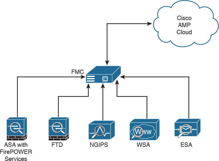
It’s very important to note that only the SHA-256 hash is sent unless you configure the policy to send files for further analysis in Threat Grid.
AMP can also provide retrospective analysis. The AMP for Networks appliance keeps data from what occurred in the past. When a file’s disposition is changed, AMP provides an historical analysis of what happened, tracing the incident/infection. With the help of AMP for Endpoints, retrospection can reach out to that host and remediate the bad file, even though that file was permitted in the past.
Web Security Appliance
For an organization to be able to protect its environment against web-based security threats, security administrators need to deploy tools and mitigation technologies that go far beyond traditional blocking of known bad websites. Today, you can download malware through compromised legitimate websites, including social media sites, advertisements in news and corporate sites, and gaming sites. Cisco has developed several tools and mechanisms to help customers combat these threats, including and Cisco Web Security Appliance (WSA), Cisco Security Management Appliance (SMA), and Cisco Cloud Web Security (CWS). These solutions enable malware detection and blocking, continuous monitoring, and retrospective alerting.
A Cisco WSA uses cloud-based intelligence from Cisco to help protect an organization before, during, and after an attack. This “lifecycle” is referred to as the attack continuum. The cloud-based intelligence includes web (URL) reputation and zero-day threat intelligence from the Talos Cisco security intelligence and research group. This threat intelligence helps security professionals stop threats before they enter the corporate network and also enables file reputation and file sandboxing to identify threats during an attack. Retrospective attack analysis allows security administrators to investigate and provide protection after an attack, when advanced malware might have evaded other layers of defense.
A Cisco WSA can be deployed in explicit proxy mode or as a transparent proxy, using the Web Cache Communication Protocol (WCCP). In explicit proxies, clients are aware of the requests that go through a proxy. On the other hand, in transparent proxies, clients are not aware of a proxy in the network; the source IP address in a request is that of the client. In transparent proxies, configuration is needed on the client. WCCP was originally developed by Cisco, but several other vendors have integrated this protocol into their products to allow clustering and transparent proxy deployments on networks using Cisco infrastructure devices (routers, switches, firewalls, and so on).
Figure 2-15 illustrates a Cisco WSA deployed as an explicit proxy.

The following are the steps illustrated in Figure 2-15:
1. An internal user makes an HTTP request to an external website. The client browser is configured to send the request to the Cisco WSA.
2. The Cisco WSA connects to the website on behalf of the internal user.
3. The firewall (Cisco ASA) is configured to only allow outbound web traffic from the Cisco WSA, and it forwards the traffic to the web server.
Figure 2-16 shows a Cisco WSA deployed as a transparent proxy.
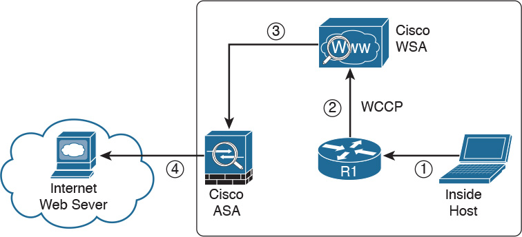
The following are the steps illustrated in Figure 2-16:
1. An internal user makes an HTTP request to an external website.
2. The internal router (R1) redirects the web request to the Cisco WSA, using WCCP.
3. The Cisco WSA connects to the website on behalf of the internal user.
4. The firewall (Cisco ASA) is configured to only allow outbound web traffic from the WSA. The web traffic is sent to the Internet web server.
Figure 2-17 demonstrates how the WCCP registration works. The Cisco WSA is the WCCP client, and the Cisco router is the WCCP server.
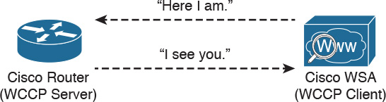
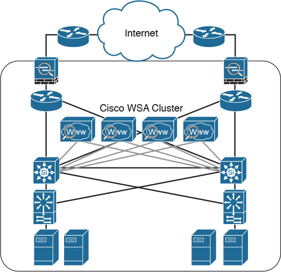
During the WCCP registration process, the WCCP client sends a registration announcement (“Here I am”) every 10 seconds. The WCCP server (the Cisco router, in this example) accepts the registration request and acknowledges it with an “I see you” WCCP message. The WCCP server waits 30 seconds before it declares the client as “inactive” (engine failed). WCCP can be used in large-scale environments. Figure 2-18 shows a cluster of Cisco WSAs, where internal Layer 3 switches redirect web traffic to the cluster.
The Cisco WSA runs the Cisco AsyncOS operating system. Cisco AsyncOS supports numerous features, including the following, that help mitigate web-based threats:
![]() Real-time antimalware adaptive scanning: The Cisco WSA can be configured to dynamically select an antimalware scanning engine based on URL reputation, content type, and scanner effectiveness. Adaptive scanning is a feature designed to increase the “catch rate” of malware embedded in images, JavaScript, text, and Adobe Flash files. Adaptive scanning is an additional layer of security on top of Cisco WSA web reputation filters that include support for Sophos, Webroot, and McAfee.
Real-time antimalware adaptive scanning: The Cisco WSA can be configured to dynamically select an antimalware scanning engine based on URL reputation, content type, and scanner effectiveness. Adaptive scanning is a feature designed to increase the “catch rate” of malware embedded in images, JavaScript, text, and Adobe Flash files. Adaptive scanning is an additional layer of security on top of Cisco WSA web reputation filters that include support for Sophos, Webroot, and McAfee.
![]() Layer 4 traffic monitor: The Cisco WSA is used to detect and block spyware. It dynamically adds IP addresses of known malware domains to databases of sites to block.
Layer 4 traffic monitor: The Cisco WSA is used to detect and block spyware. It dynamically adds IP addresses of known malware domains to databases of sites to block.
![]() Third-party DLP integration: The Cisco WSA redirects all outbound traffic to a third-party DLP appliance, allowing deep content inspection for regulatory compliance and data exfiltration protection. It enables an administrator to inspect web content by title, metadata, and size, and to even prevent users from storing files to cloud services such as Dropbox and Google Drive.
Third-party DLP integration: The Cisco WSA redirects all outbound traffic to a third-party DLP appliance, allowing deep content inspection for regulatory compliance and data exfiltration protection. It enables an administrator to inspect web content by title, metadata, and size, and to even prevent users from storing files to cloud services such as Dropbox and Google Drive.
![]() File reputation: Using threat information from Cisco Talos, this file reputation threat intelligence is updated every 3 to 5 minutes.
File reputation: Using threat information from Cisco Talos, this file reputation threat intelligence is updated every 3 to 5 minutes.
![]() File sandboxing: If malware is detected, the Cisco AMP capabilities can put files in a sandbox to inspect the malware’s behavior and combine the inspection with machine-learning analysis to determine the threat level. Cisco Cognitive Threat Analytics (CTA) uses machine-learning algorithms to adapt over time.
File sandboxing: If malware is detected, the Cisco AMP capabilities can put files in a sandbox to inspect the malware’s behavior and combine the inspection with machine-learning analysis to determine the threat level. Cisco Cognitive Threat Analytics (CTA) uses machine-learning algorithms to adapt over time.
![]() File retrospection: After a malicious attempt or malware is detected, the Cisco WSA continues to cross-examine files over an extended period of time.
File retrospection: After a malicious attempt or malware is detected, the Cisco WSA continues to cross-examine files over an extended period of time.
![]() Application visibility and control: The Cisco ASA can inspect and even block applications that are not allowed by the corporate security polity. For example, an administrator can allow users to use social media sites such as Facebook but block micro-applications such as Facebook games.
Application visibility and control: The Cisco ASA can inspect and even block applications that are not allowed by the corporate security polity. For example, an administrator can allow users to use social media sites such as Facebook but block micro-applications such as Facebook games.
Email Security Appliance
Users are no longer accessing email only from the corporate network or from a single device. Cisco provides cloud-based, hybrid, and on-premises solutions based on the Email Security Appliance (ESA) that can help protect any dynamic environment. This section introduces these solutions and technologies and explains how users can use threat intelligence to detect, analyze, and protect against both known and emerging threats.
The following are the most common email-based threats:
![]() Spam: Unsolicited email messages that advertise a service, a scam (typically), or a message with malicious intent. Email spam continues to be a major threat because it can be used to spread malware.
Spam: Unsolicited email messages that advertise a service, a scam (typically), or a message with malicious intent. Email spam continues to be a major threat because it can be used to spread malware.
![]() Malware attachments: Email messages containing malicious software (malware).
Malware attachments: Email messages containing malicious software (malware).
![]() Phishing: An attacker’s attempt to fool a user into thinking that the email communication comes from a legitimate entity or site, such as a bank, social media website, online payment processor, or even the corporate IT department. The goal of a phishing email is to steal a user’s sensitive information, such as user credentials, bank account information, and so on.
Phishing: An attacker’s attempt to fool a user into thinking that the email communication comes from a legitimate entity or site, such as a bank, social media website, online payment processor, or even the corporate IT department. The goal of a phishing email is to steal a user’s sensitive information, such as user credentials, bank account information, and so on.
![]() Spear phishing: This involves phishing attempts that are more targeted. Spear-phishing emails are directed to specific individuals or organizations. For instance, an attacker might perform a passive reconnaissance on an individual or organization by gathering information from social media sites (for example, Twitter, LinkedIn, and Facebook) and other online resources. Then the attacker might tailor a more directed and relevant message to the victim to increase the probability that the user will be fooled into following a malicious link, clicking an attachment containing malware, or simply replying to the email and providing sensitive information. Another phishing-based attack, called whaling, specifically targets executives and high-profile users.
Spear phishing: This involves phishing attempts that are more targeted. Spear-phishing emails are directed to specific individuals or organizations. For instance, an attacker might perform a passive reconnaissance on an individual or organization by gathering information from social media sites (for example, Twitter, LinkedIn, and Facebook) and other online resources. Then the attacker might tailor a more directed and relevant message to the victim to increase the probability that the user will be fooled into following a malicious link, clicking an attachment containing malware, or simply replying to the email and providing sensitive information. Another phishing-based attack, called whaling, specifically targets executives and high-profile users.
The Cisco ESA runs the Cisco AsyncOS operating system. Cisco AsyncOS supports numerous features that help mitigate email-based threats. The following are examples of the features supported by the Cisco ESA:
![]() Access control: Controlling access for inbound senders, according to a sender’s IP address, IP address range, or domain name.
Access control: Controlling access for inbound senders, according to a sender’s IP address, IP address range, or domain name.
![]() Anti-spam: Multilayer filters based on Cisco SenderBase reputation and Cisco antispam integration. The antispam reputation and zero-day threat intelligence are fueled by the Cisco security intelligence and research group named Talos.
Anti-spam: Multilayer filters based on Cisco SenderBase reputation and Cisco antispam integration. The antispam reputation and zero-day threat intelligence are fueled by the Cisco security intelligence and research group named Talos.
![]() Network antivirus: Network antivirus capabilities at the gateway. Cisco partnered with Sophos and McAfee, supporting their antivirus scanning engines.
Network antivirus: Network antivirus capabilities at the gateway. Cisco partnered with Sophos and McAfee, supporting their antivirus scanning engines.
![]() Advanced Malware Protection (AMP): Allows security administrators to detect and block malware and perform continuous analysis and retrospective alerting.
Advanced Malware Protection (AMP): Allows security administrators to detect and block malware and perform continuous analysis and retrospective alerting.
![]() Data loss prevention (DLP): The ability to detect any sensitive emails and documents leaving the corporation. The Cisco ESA integrates RSA email DLP for outbound traffic.
Data loss prevention (DLP): The ability to detect any sensitive emails and documents leaving the corporation. The Cisco ESA integrates RSA email DLP for outbound traffic.
![]() Email encryption: The ability to encrypt outgoing mail to address regulatory requirements. The administrator can configure an encryption policy on the Cisco ESA and use a local key server or hosted key service to encrypt the message.
Email encryption: The ability to encrypt outgoing mail to address regulatory requirements. The administrator can configure an encryption policy on the Cisco ESA and use a local key server or hosted key service to encrypt the message.
![]() Email authentication: A few email authentication mechanisms include Sender Policy Framework (SPF), Sender ID Framework (SIDF), and DomainKeys Identified Mail (DKIM) verification of incoming mail, as well as DomainKeys and DKIM signing of outgoing mail.
Email authentication: A few email authentication mechanisms include Sender Policy Framework (SPF), Sender ID Framework (SIDF), and DomainKeys Identified Mail (DKIM) verification of incoming mail, as well as DomainKeys and DKIM signing of outgoing mail.
![]() Outbreak filters: Preventive protection against new security outbreaks and email-based scams using Cisco’s Security Intelligence Operations (SIO) threat intelligence information.
Outbreak filters: Preventive protection against new security outbreaks and email-based scams using Cisco’s Security Intelligence Operations (SIO) threat intelligence information.
NOTE
Cisco SenderBase (see www.senderbase.org) is the world’s largest email and web traffic monitoring network. It provides real-time threat intelligence powered by Cisco SIO.
The Cisco ESA acts as the email gateway for an organization, handling all email connections, accepting messages, and relaying messages to the appropriate systems. The Cisco ESA can service email connections from the Internet to users inside a network and from systems inside the network to the Internet. Email connections use Simple Mail Transfer Protocol (SMTP). The ESA services all SMTP connections, by default acting as the SMTP gateway.
TIP
Mail gateways are also known as mail exchangers (MX).
The Cisco ESA uses listeners to handle incoming SMTP connection requests. A listener defines an email processing service that is configured on an interface in the Cisco ESA. Listeners apply to email entering the appliance from either the Internet or internal systems.
The following listeners can be configured:
![]() Public listeners for email coming in from the Internet.
Public listeners for email coming in from the Internet.
![]() Private listeners for email coming from hosts in the corporate (inside) network. (These emails are typically from internal groupware, Exchange, POP, or IMAP email servers.)
Private listeners for email coming from hosts in the corporate (inside) network. (These emails are typically from internal groupware, Exchange, POP, or IMAP email servers.)
Cisco ESA listeners are often referred to as SMTP daemons, and they run on specific Cisco ESA interfaces. When a listener is configured, the following information must be provided:
![]() Listener properties such as a specific interface in the Cisco ESA and the TCP port that will be used. The listener properties must also indicate whether the listener is public or private.
Listener properties such as a specific interface in the Cisco ESA and the TCP port that will be used. The listener properties must also indicate whether the listener is public or private.
![]() The hosts that are allowed to connect to the listener, using a combination of access control rules. An administrator can specify which remote hosts can connect to the listener.
The hosts that are allowed to connect to the listener, using a combination of access control rules. An administrator can specify which remote hosts can connect to the listener.
![]() The local domains for which public listeners accept messages.
The local domains for which public listeners accept messages.
Cisco Security Management Appliance
Cisco Security Management Appliance (SMA) is a Cisco product that centralizes the management and reporting for one or more Cisco ESAs and Cisco WSAs. Cisco SMA enables you to consistently enforce policy and enhance threat protection. Figure 2-19 shows a Cisco SMA that is controlling Cisco ESAs and Cisco WSAs in different geographic locations (New York, Raleigh, Paris, and London).

The Cisco SMA can be deployed with physical appliances or as virtual appliances.
Cisco Identity Services Engine
The Cisco Identity Services Engine (ISE) is a comprehensive security identity management solution designed to function as a policy decision point for network access. It allows security administrators to collect real-time contextual information from a network, its users, and devices. Cisco ISE is the central policy management platform in the Cisco TrustSec solution. It supports a comprehensive set of AAA (authentication, authorization, and accounting), posture, and network profiler features in a single device. Cisco ISE provides the AAA functionality of legacy Cisco products such as the Cisco Access Control Server (ACS).
Cisco ISE allows security administrators to provide network guest access management and wide-ranging client provisioning policies, including 802.1X environments. The support of TrustSec features such as security group tags (SGTs) and security group access control lists (SGACLs) make the Cisco ISE a complete identity services solution. Cisco ISE supports policy sets, which let a security administrator group sets of authentication and authorization policies.
Cisco ISE provides Network Admission Control (NAC) features, including posture policies, to enforce configuration of end-user devices with the most up-to-date security settings or applications before they enter the network. The Cisco ISE supports the following agent types for posture assessment and compliance:
![]() Cisco NAC Web Agent: A temporary agent that is installed in end-user machines at the time of login. The Cisco NAC Web Agent is not visible on the end-user machine after the user terminates the session.
Cisco NAC Web Agent: A temporary agent that is installed in end-user machines at the time of login. The Cisco NAC Web Agent is not visible on the end-user machine after the user terminates the session.
![]() Cisco NAC Agent: An agent that is installed permanently on a Windows or Mac OS X client system.
Cisco NAC Agent: An agent that is installed permanently on a Windows or Mac OS X client system.
![]() Cisco AnyConnect Secure Mobility Client: An agent that is installed permanently on a Windows or Mac OS X client system.
Cisco AnyConnect Secure Mobility Client: An agent that is installed permanently on a Windows or Mac OS X client system.
Cisco ISE provides a comprehensive set of features to allow corporate users to connect their personal devices—such as mobile phones, tablets, laptops, and other network devices—to the network. Such a bring-your-own-device (BYOD) system introduces many challenges in terms of protecting network services and enterprise data. Cisco ISE provides support for multiple mobile device management (MDM) solutions to enforce policy on endpoints. ISE can be configured to redirect users to MDM onboarding portals and prompt them to update their devices before they can access the network. Cisco ISE can also be configured to provide Internet-only access to users who are not compliant with MDM policies.
Cisco ISE supports the Cisco Platform Exchange Grid (pxGrid), a multivendor, cross-platform network system that combines different parts of an IT infrastructure, such as the following:
![]() Security monitoring
Security monitoring
![]() Detection systems
Detection systems
![]() Network policy platforms
Network policy platforms
![]() Asset and configuration management
Asset and configuration management
![]() Identity and access management platforms
Identity and access management platforms
Cisco pxGrid has a unified framework with an open application programming interface (API) designed in a hub-and-spoke architecture. pxGrid is used to enable the sharing of contextual-based information from a Cisco ISE session directory to other policy network systems, such as Cisco IOS devices and the Cisco ASA.
The Cisco ISE can be configured as a certificate authority (CA) to generate and manage digital certificates for endpoints. Cisco ISE CA supports standalone and subordinate deployments.
Cisco ISE software can be installed on a range of physical appliances or on a VMware server (Cisco ISE VM). The Cisco ISE software image does not support the installation of any other packages or applications on this dedicated platform.
Security Cloud-based Solutions
Several cloud-based security solutions are also available in the market. For example, Cisco provides the following cloud-based security services:
![]() Cisco Cloud Web Security (CWS)
Cisco Cloud Web Security (CWS)
![]() Cisco Cloud Email Security (CES)
Cisco Cloud Email Security (CES)
![]() Cisco AMP Threat Grid
Cisco AMP Threat Grid
![]() Cisco Threat Awareness Service
Cisco Threat Awareness Service
![]() CloudLock
CloudLock
The following sections describe these cloud-based security services.
Cisco Cloud Web Security
Cisco Cloud Web Security (CWS) is a cloud-based security service that provides worldwide threat intelligence, advanced threat defense capabilities, and roaming user protection. The Cisco CWS service uses web proxies in the Cisco cloud environment that scan traffic for malware and policy enforcement. Cisco customers can connect to the Cisco CWS service directly by using a proxy auto-configuration (PAC) file in the user endpoint or through connectors integrated into the following Cisco products:
![]() Cisco ISR G2 routers
Cisco ISR G2 routers
![]() Cisco ASA
Cisco ASA
![]() Cisco WSA
Cisco WSA
![]() Cisco AnyConnect Secure Mobility Client
Cisco AnyConnect Secure Mobility Client
NOTE
Cisco is always adding more functionality to their products. The number of connectors may increase throughout time. Those in the preceding list are the ones available at the time of writing.
Organizations using the transparent proxy functionality through a connector can get the most out of their existing infrastructure. In addition, the scanning is offloaded from the hardware appliances to the cloud, thus reducing the impact to hardware utilization and reducing network latency. Figure 2-20 illustrates how the transparent proxy functionality through a connector works.

In Figure 2-20, the Cisco ASA is enabled with the Cisco CWS connector at a branch office, and it protects the corporate users at the branch office with these steps:
1. An internal user makes an HTTP request to an external website (example.org).
2. The Cisco ASA forwards the request to the Cisco CWS global cloud infrastructure.
3. Cisco CWS notices that example.org has some web content (ads) that is redirecting the user to a known malicious site.
4. Cisco CWS blocks the request to the malicious site.
Cisco Cloud Email Security
Cisco Cloud Email Security (CES) provides a cloud-based solution that allows companies to outsource the management of their email security. The service provides email security instances in multiple Cisco data centers to enable high availability.
The Cisco Hybrid Email Security solution combines both cloud-based and on-premises ESAs. This hybrid solution helps Cisco customers reduce their onsite email security footprint and outsource a portion of their email security to Cisco, while still allowing them to maintain control of confidential information within their physical boundaries. Many organizations must comply with regulations that require them to keep sensitive data physically on their premises. The Cisco Hybrid Email Security solution allows network security administrators to remain compliant and to maintain advanced control with encryption, DLP, and onsite identity-based integration.
Cisco AMP Threat Grid
Cisco acquired a security company called Threat Grid that provides cloud-based and on-premises malware analysis solutions. Cisco integrated Cisco AMP and Threat Grid to provide a solution for advanced malware analysis with deep threat analytics. The Cisco AMP Threat Grid integrated solution analyzes millions of files and correlates them with hundreds of millions of malware samples. This provides a look into attack campaigns and how malware is distributed. This solution provides a security administrator with detailed reports of indicators of compromise and threat scores that help prioritize mitigations and recover from attacks. Cisco AMP Threat Grid crowdsources malware from a closed community and analyzes all samples using highly secure proprietary techniques that include static and dynamic analysis. These are different from traditional sandboxing technologies. The Cisco AMP Threat Grid analysis exists outside the virtual environment, identifying malicious code designed to evade analysis. There is a feature in Cisco AMP Threat Grid called Glovebox that helps you interact with the malware in real time, recording all activity for future playback and reporting. Advanced malware uses numerous evasion techniques to determine whether it is being analyzed in a sandbox. Some of these samples require user interaction. Glovebox dissects these samples without infecting your network while the samples are being analyzed. Glovebox is a powerful tool against advanced malware that allows analysts to open applications and replicate a workflow process, see how the malware behaves, and even reboot the virtual machine.
NOTE
The Mac OS X connector does not support SWF files. The Windows connector does not scan ELF, JAVA, MACHO, and MACHO_UNIBIN files at the time of this writing. The Android AMP connector scans APK files.
Cisco Threat Awareness Service
The Cisco Threat Awareness Service (CTAS) is a threat intelligence service that provides Cisco customers with network visibility by making security information available 24 hours a day, 7 days a week. CTAS is a cloud-based service that is accessed via a web browser. It allows Cisco customers to maintain visibility into inbound and outbound network activity from the outside and displays potential threats requiring additional attention by the network security staff. CTAS requires no configuration changes, network infrastructure, or new software, as it tracks the domain names and IP addresses of Cisco customer premises to alert on suspicious activity or requests. CTAS also provides remediation recommendations through its web portal.
Cisco provides a base offer of the CTAS service with Cisco Smart Net Total Care Service at no additional cost. A premium offer is available as a yearly subscription for customers looking to track an unlimited number of domain names and IP addresses.
NOTE
You can obtain more information about CTAS at http://www.cisco.com/c/en/us/products/security/sas-threat-management.html.
OpenDNS
Cisco acquired a company called OpenDNS that provides DNS services, threat intelligence, and threat enforcement at the DNS layer. OpenDNS has a global network that delivers advanced security solutions (as a cloud-based service) regardless of where Cisco customer offices or employees are located. This service is extremely easy to deploy and easy to manage. Cisco has also incorporated the innovative advancements to threat research and threat-centric security that OpenDNS has developed to block advanced cyber security threats with other security and networking products. Millions of people use OpenDNS, including thousands of companies, from Fortune 500 enterprises to small businesses.
OpenDNS provides a free DNS service for individuals, students, and small businesses. You can just simply configure your endpoint (laptop, desktop, mobile device, server, or your DHCP server) to point to OpenDNS servers: 208.67.222.222 and/or 208.67.220.220.
It also provides the following premium services:
![]() OpenDNS Umbrella: An enterprise advanced network security service to protect any device, anywhere. This service blocks known malicious sites from being “resolved” in DNS. It provides an up-to-the-minute view and analysis of at least 2% of the world’s Internet activity to stay ahead of attacks. This service provides threat intelligence by seeing where attacks are being staged on the Internet.
OpenDNS Umbrella: An enterprise advanced network security service to protect any device, anywhere. This service blocks known malicious sites from being “resolved” in DNS. It provides an up-to-the-minute view and analysis of at least 2% of the world’s Internet activity to stay ahead of attacks. This service provides threat intelligence by seeing where attacks are being staged on the Internet.
![]() OpenDNS Investigate: This is a premium service that provides you information on where attacks are forming, allowing you to investigate incidents faster and prioritize them better. With the Investigate service, you can see up-to-the-minute threat data and historical context about all domains on the Internet and respond quickly to critical incidents. It provides a dynamic search engine and a RESTful API that you can use to automatically bring critical data into the security management and threat intelligence systems deployed in your organization. It also provides predictive threat intelligence using statistical models for real-time and historical data to predict domains that are likely malicious and could be part of future attacks.
OpenDNS Investigate: This is a premium service that provides you information on where attacks are forming, allowing you to investigate incidents faster and prioritize them better. With the Investigate service, you can see up-to-the-minute threat data and historical context about all domains on the Internet and respond quickly to critical incidents. It provides a dynamic search engine and a RESTful API that you can use to automatically bring critical data into the security management and threat intelligence systems deployed in your organization. It also provides predictive threat intelligence using statistical models for real-time and historical data to predict domains that are likely malicious and could be part of future attacks.
CloudLock
Cisco acquired a company called CloudLock that creates solutions to protect their customers against data breaches in any cloud environment and application (app) through a highly configurable cloud-based data loss prevention (DLP) architecture. CloudLock has numerous out-of-the-box policies and a wide range of automated, policy-driven response actions, including the following:
![]() File-level encryption
File-level encryption
![]() Quarantine
Quarantine
![]() End-user notifications
End-user notifications
These policies are designed to provide common data protection and help with compliance. CloudLock also can monitor data at rest within platforms via an API and provide visibility of user activity through retroactive monitoring capabilities. This solution helps organizations defend against account compromises with cross-platform User and Entity Behavior Analytics (UEBA) for Software as a Service (SaaS), Infrastructure as a Service (IaaS), Platform as a Service (PaaS), and Identity as a Service (IDaaS) environments. CloudLock uses advanced machine learning to be able to detect anomalies and to identify activities in different countries that can be whitelisted or blacklisted in the platform. CloudLock Apps Firewall is a feature that discovers and controls malicious cloud apps that may be interacting with the corporate network.
Cisco NetFlow
NetFlow is a Cisco technology that provides comprehensive visibility into all network traffic that traverses a Cisco-supported device. Cisco invented NetFlow and is the leader in IP traffic flow technology. NetFlow was initially created for billing and accounting of network traffic and to measure other IP traffic characteristics such as bandwidth utilization and application performance. NetFlow has also been used as a network capacity planning tool and to monitor network availability. Nowadays, NetFlow is used as a network security tool because its reporting capabilities provide nonrepudiation, anomaly detection, and investigative capabilities. As network traffic traverses a NetFlow-enabled device, the device collects traffic flow data and provides a network administrator or security professional with detailed information about such flows.
NetFlow provides detailed network telemetry that can be used to see what is actually happening across the entire network. You can use NetFlow to identify DoS attacks, quickly identify compromised endpoints and network infrastructure devices, and monitor network usage of employees, contractors, or partners. NetFlow is also often used to obtain network telemetry during security incident response and forensics. You can also take advantage of NetFlow to detect firewall misconfigurations and inappropriate access to corporate resources.
NetFlow supports both IP Version 4 (IPv4) and IP Version 6 (IPv6).
There’s also the Internet Protocol Flow Information Export (IPFIX), which is a network flow standard led by the Internet Engineering Task Force (IETF). IPFIX was designed to create a common, universal standard of export for flow information from routers, switches, firewalls, and other infrastructure devices. IPFIX defines how flow information should be formatted and transferred from an exporter to a collector. IPFIX is documented in RFC 7011 through RFC 7015 and RFC 5103. Cisco NetFlow Version 9 is the basis and main point of reference for IPFIX. IPFIX changes some of the terminologies of NetFlow, but in essence they are the same principles of NetFlow Version 9.
Traditional Cisco NetFlow records are usually exported via UDP messages. The IP address of the NetFlow collector and the destination UDP port must be configured on the sending device. The NetFlow standard (RFC 3954) does not specify a specific NetFlow listening port. The standard or most common UDP port used by NetFlow is UDP port 2055, but other ports, such as 9555, 9995, 9025, and 9026, can also be used. UDP port 4739 is the default port used by IPFIX.
What Is the Flow in NetFlow?
A flow is a unidirectional series of packets between a given source and destination. Figure 2-21 shows an example of a flow between a client and a server.

In a flow, the same source and destination IP addresses, source and destination ports, and IP protocol are shared. This is often referred to as the five-tuple.
In Figure 2-21, the client (source) establishes a connection to the server (destination). When the traffic traverses the router (configured for NetFlow), it generates a flow record. At the very minimum, the five-tuple is used to identify the flow in the NetFlow database of flows kept on the device. This database is often called the NetFlow cache. Here is the five-tuple for the basic flow represented in Figure 2-21:
![]() Source address: 192.168.1.1
Source address: 192.168.1.1
![]() Destination IP address: 10.10.10.10
Destination IP address: 10.10.10.10
![]() Source port: 15728
Source port: 15728
![]() Destination port: 80
Destination port: 80
![]() Protocol: TCP (since HTTP is carried over TCP)
Protocol: TCP (since HTTP is carried over TCP)
Many people often confuse a flow with a session. All traffic in a flow is going in the same direction; however, when the client establishes the HTTP connection (session) to the server and accesses a web page, it represents two separate flows. The first flow is the traffic from the client to the server, and the other flow is from the server to the client.
There are different versions of NetFlow. Depending on the version of NetFlow, the router can also gather additional information, such as type of service (ToS) byte, differentiated services code point (DSCP), the device’s input interface, TCP flags, byte counters, and start and end times.
Flexible NetFlow, Cisco’s next-generation NetFlow, can track a wide range of Layer 2, IPv4, and IPv6 flow information, such as the following:
![]() Source and destination MAC addresses
Source and destination MAC addresses
![]() Source and destination IPv4 or IPv6 addresses
Source and destination IPv4 or IPv6 addresses
![]() Source and destination ports
Source and destination ports
![]() DSCP
DSCP
![]() Packet and byte counts
Packet and byte counts
![]() Flow timestamps
Flow timestamps
![]() Input and output interface numbers
Input and output interface numbers
![]() TCP flags and encapsulated protocol (TCP/UDP) and individual TCP flags
TCP flags and encapsulated protocol (TCP/UDP) and individual TCP flags
![]() Sections of a packet for deep packet inspection
Sections of a packet for deep packet inspection
![]() All fields in an IPv4 header, including IP-ID and TTL
All fields in an IPv4 header, including IP-ID and TTL
![]() All fields in an IPv6 header, including Flow Label and Option Header
All fields in an IPv6 header, including Flow Label and Option Header
![]() Routing information, such as next-hop address, source autonomous system number (ASN), destination ASN, source prefix mask, destination prefix mask, Border Gateway Protocol (BGP) next hop, and BGP policy accounting traffic index
Routing information, such as next-hop address, source autonomous system number (ASN), destination ASN, source prefix mask, destination prefix mask, Border Gateway Protocol (BGP) next hop, and BGP policy accounting traffic index
NetFlow vs. Full Packet Capture
A substantial difference exists between a full packet capture and the information collected in NetFlow. Think about NetFlow as being a technology to collect metadata on all transactions/flows traversing the network.
Collecting packet captures in your network involves “tapping” or capturing a mirror image of network packets as they move through the network. Cisco switches allow for the setup of mirror ports that do not impact network performance. Typically, a deep packet inspection (DPI) application is connected to a mirror port, and certain information is extracted from the packets so that you can find out what is happening on your network. DPI solutions range from open source packet capture software such as Wireshark to commercial applications that can provide more detailed analysis.
You may be asking, “How does NetFlow compare to traditional packet capture technologies that leverage SPAN ports or Ethernet taps?” The cost and the amount of data that needs to be analyzed is much higher with packet captures. In a lot of scenarios and in most cases, you don’t need heavyweight packet capture technology everywhere throughout your network if you have an appropriate NetFlow collection and analysis ecosystem. In fact, you probably couldn’t afford it even if you did need it. For instance, the storage and compute power needed to analyze full packet captures can lead to much higher costs. However, there is definitely also a good benefit to collecting full packet capture data.
If you really must have latency and packet capture capabilities, Cisco through its Lancope acquisition offers a device called a FlowSensor that plugs into a SPAN, tap, or mirror port to generate NetFlow suitable for consumption by any NetFlow v9–capable collector.
The NetFlow Cache
The three types of NetFlow cache are as follows:
![]() Normal cache
Normal cache
![]() Immediate cache
Immediate cache
![]() Permanent cache
Permanent cache
The “normal cache” is the default cache type in many infrastructure devices enabled with NetFlow and Flexible NetFlow. The entries in the flow cache are removed (aged out) based on the configured timeout active seconds and timeout inactive seconds settings.
In the immediate cache, the flows account for a single packet. This type of NetFlow cache is desirable for real-time traffic monitoring and distributed DoS (DDoS) detection. The immediate NetFlow cache is used when only very small flows are expected (for example, sampling).
TIP
You have to keep in mind that the immediate cache may result in a large amount of export data.
The permanent cache is used to track a set of flows without expiring the flows from the cache. The entire cache is periodically exported (update timer). Another thing to highlight is that the cache is a configurable value. After the cache is full, new flows will not be monitored. The permanent cache uses update counters rather than delta counters.
Data Loss Prevention
Data loss prevention (DLP) is the ability to detect any sensitive emails, documents, or information leaving your organization. Several products in the industry inspect for traffic to prevent data loss in an organization. Several Cisco security products integrate with third-party products to provide this type of solution. For example, the Cisco ESA integrates RSA email DLP for outbound email traffic. Also, the Cisco Cloud Email Service and the Cisco Hybrid Email Security solution allow network security administrators to remain compliant and to maintain advanced control with encryption, DLP, and onsite identity-based integration. Another product family that integrates with other DLP solutions is the Cisco WSA, which redirects all outbound traffic to a third-party DLP appliance, allowing deep content inspection for regulatory compliance and data exfiltration protection. It enables an administrator to inspect web content by title, metadata, and size and even to prevent users from storing files to cloud services such as Dropbox and Google Drive.
Cisco CloudLock is also another DLP solution. CloudLock is designed to protect organizations of any type against data breaches in any type of cloud environment or application (app) through a highly configurable cloud-based DLP architecture.
CloudLock is an API-driven solution that provides a deep level of integration with monitored SaaS, IaaS, PaaS, and IDaaS solutions. It provides advanced cloud DLP functionality that includes out-of-the-box policies designed to help administrators maintain compliance. Additionally, CloudLock can monitor data at rest within platforms via APIs and provide a comprehensive picture of user activity through retroactive monitoring capabilities. Security administrators can mitigate risk efficiently using CloudLock’s configurable, automated response actions, including encryption, quarantine, and end-user notification.
Data loss doesn’t always take place because of a complex attack carried out by an external attacker; many data loss incidents have been carried out by internal (insider) attacks. Data loss can also happen because of human negligence or ignorance—for example, an internal employee sending sensitive corporate email to their personal email account, or uploading sensitive information to an unapproved cloud provider. This is why maintaining visibility into what’s coming as well as leaving the organization is so important.
Exam Preparation Tasks
Review All Key Topics
Review the most important topics in the chapter, noted with the Key Topic icon in the outer margin of the page. Table 2-2 lists a reference of these key topics and the page numbers on which each is found.


Complete Tables and Lists from Memory
Print a copy of Appendix B, “Memory Tables,” (found on the book website), or at least the section for this chapter, and complete the tables and lists from memory. Appendix C, “Memory Tables Answer Key,” also on the website, includes completed tables and lists to check your work.
Define Key Terms
Define the following key terms from this chapter, and check your answers in the glossary:
network firewalls
ACLs
network address translation
DLP
AMP
IPS
NetFlow
Q&A
The answers to these questions appear in Appendix A, “Answers to the ‘Do I Know This Already?’ Quizzes and Q&A Questions.” For more practice with exam format questions, use the exam engine on the website.
1. Which of the following explains features of a traditional stateful firewall?
a. Access control is done by application awareness and visibility.
b. Access control is done by the five-tuple (source and destination IP addresses, source and destination ports, and protocol).
c. Application inspection is not supported.
d. Traditional stateful firewalls support advanced malware protection.
2. Which of the following describes a traditional IPS?
a. A network security appliance or software technology that resides in stateful firewalls
b. A network security appliance or software technology that supports advanced malware protection
c. A network security appliance or software technology that inspects network traffic to detect and prevent security threats and exploits
d. A virtual appliance that can be deployed with the Cisco Adaptive Security Manager (ASM)
3. Which of the following is true about NetFlow?
a. NetFlow can be deployed to replace IPS devices.
b. NetFlow provides information about network session data.
c. NetFlow provides user authentication information.
d. NetFlow provides application information.
4. What is DLP?
a. An email inspection technology used to prevent phishing attacks
b. A software or solution for making sure that corporate users do not send sensitive or critical information outside the corporate network
c. A web inspection technology used to prevent phishing attacks
d. A cloud solution used to provide dynamic layer protection
5. Stateful and traditional firewalls can analyze packets and judge them against a set of predetermined rules called access control lists (ACLs). They inspect which of the following elements within a packet?
a. Session headers
b. NetFlow flow information
c. Source and destination ports and source and destination IP addresses
d. Protocol information
6. Which of the following are Cisco cloud security solutions?
a. CloudDLP
b. OpenDNS
c. CloudLock
d. CloudSLS
7. Cisco pxGrid has a unified framework with an open API designed in a hub-and-spoke architecture. pxGrid is used to enable the sharing of contextual-based information from which devices?
a. From a Cisco ASA to the Cisco OpenDNS service
b. From a Cisco ASA to the Cisco WSA
c. From a Cisco ASA to the Cisco FMC
d. From a Cisco ISE session directory to other policy network systems, such as Cisco IOS devices and the Cisco ASA
8. Which of the following is true about heuristic-based algorithms?
a. Heuristic-based algorithms may require fine tuning to adapt to network traffic and minimize the possibility of false positives.
b. Heuristic-based algorithms do not require fine tuning.
c. Heuristic-based algorithms support advanced malware protection.
d. Heuristic-based algorithms provide capabilities for the automation of IPS signature creation and tuning.
9. Which of the following describes the use of DMZs?
a. DMZs can be configured in Cisco IPS devices to provide additional inspection capabilities.
b. DMZs can automatically segment the network traffic.
c. DMZs can serve as segments on which a web server farm resides or as extranet connections to business partners.
d. DMZs are only supported in next-generation firewalls.
10. Which of the following has the most storage requirements?
a. NetFlow
b. Syslog
c. Full packet captures