
Chapter 5
Domain 4: Communication and Network Security (Designing and Protecting Network Security)
Abstract
Domain 4: Communications and Network Security, covered in Chapter 5, is another very technical domain to be tested. One of the most technical of the domains included in the CISSP, Domain 4 requires an understanding of networking and the TCP/IP suite of protocols at a fairly substantial level of depth. Networking hardware such as routers, switches, and the less common repeaters, hubs, and bridges are all presented within this domain. Technical aspects of Intrusion Detection Systems (IDS), Intrusion Prevention Systems (IPS), Virtual Private Networks (VPN), 802.11 wireless, Radio Frequency ID (RFID), and also authentication devices and protocols are found in this large domain. More recently added topics such as endpoint security, remote access, and virtualization are also represented in Chapter 5.
Keywords
OSI model
the TCP/IP model
Packet-switched network
Switch
Router
Packet Filter Firewall
Stateful Firewall
Carrier Sense Multiple Access
Exam objectives in this chapter
• Network Architecture and Design
• Secure Network Devices and Protocols
• Secure Communications
Unique Terms and Definitions
• The OSI model—a network model with seven layers: physical, data link, network, transport, session, presentation, and application
• The TCP/IP model—a simpler network model with four layers: network access, Internet, transport, and application
• Packet-switched network—a form of networking where bandwidth is shared and data is carried in units called packets
• Switch—a layer 2 device that carries traffic on one LAN, based on MAC addresses
• Router—a layer 3 device that routes traffic from one LAN to another, based on IP addresses
• Packet Filter and Stateful Firewalls—devices that filter traffic based on OSI layers 3 (IP addresses) and 4 (ports)
• Carrier Sense Multiple Access (CSMA)—a method used by Ethernet networks to allow shared usage of a baseband (one-channel) network and avoid collisions (multiple interfering signals)
Introduction
Communications and Network Security are fundamental to our modern life. The Internet, the World Wide Web, online banking, instant messaging email, and many other technologies rely on network security: our modern world cannot exist without it. Communications and Network Security focuses on the confidentiality, integrity and availability of data in motion.
Communications and Network Security is one of the largest domains in the Common Body of Knowledge, and contains more concepts than any other domain. This domain is also one of the most technically deep domains, requiring technical knowledge down to packets, segments, frames, and their headers. Understanding this domain is critical to ensure success on the exam.
Network Architecture and Design
Our first section is network architecture and design. We will discuss how networks should be designed and the controls they may contain, focusing on deploying defense-in-depth strategies, and weighing the cost and complexity of a network control versus the benefit provided.
Network Defense-in-Depth
Communications and Network Security employs defense-in-depth, as we do in all 8 domains of the common body of knowledge. Any one control may fail, so multiple controls are always recommended. Before malware (malicious software) can reach a server, it may be analyzed by: routers, firewalls, intrusion detection systems, and host-based protections such as antivirus software. Hosts are patched, and users have been provided with awareness of malware risks. The failure of any one of these controls should not lead to compromise.
No single concept described in this chapter (or any other) provides sufficient defense against possible attacks: these concepts should be used in concert.
Fundamental Network Concepts
Before we can discuss specific Communications and Network Security concepts, we need to understand the fundamental concepts behind them. Terms like “broadband” are often used informally: the exam requires a precise understanding of information security terminology.
Simplex, Half Duplex and Full Duplex Communication
Simplex communication is one-way, like a car radio tuned to a music station. Half-duplex communication sends or receives at one time only (not simultaneously), like a walkie-talkie. Full-duplex communications send and receive simultaneously, like two people having a face-to-face conversation.
Baseband and Broadband
Baseband networks have one channel, and can only send one signal at a time. Ethernet networks are baseband: a “100baseT” UTP cable means 100 megabit, baseband, and twisted pair. Broadband networks have multiple channels and can send multiple signals at a time, like cable TV. The term “channel” derives from communications like radio.
Analog & Digital
Analog communications are what our ears hear, a continuous wave of information. The original phone networks were analog networks, designed to carry the human voice. Digital communications transfer data in bits: ones and zeroes. A vinyl record is analog; a compact disc is digital.
LANS, WANS, MANS, GANS and PANS
A LAN is a Local Area Network. A LAN is a comparatively small network, typically confined to a building or an area within one. A MAN is a Metropolitan Area Network, which is typically confined to a city, a zip code, a campus, or office park. A WAN is a Wide Area Network, typically covering cities, states, or countries. A GAN is a Global Area Network, a global collection of WANs.
The Global Information Grid (GIG) is the U.S. Department of Defense (DoD) global network, one of the largest private networks in the world.
At the other end of the spectrum, the smallest of these networks are PANs: Personal Area Networks, with a range of 100 meters or much less. Low-power wireless technologies such as Bluetooth use PANs.
Internet, Intranet and Extranet
The Internet is a global collection of peered networks running TCP/IP, providing best effort service. An Intranet is a privately owned network running TCP/IP, such as a company network. An Extranet is a connection between private Intranets, such as connections to business partner Intranets.
Circuit-Switched and Packet-Switched Networks
The original voice networks were circuit-switched: a dedicated circuit or channel (portion of a circuit) was dedicated between two nodes. Circuit-switched networks can provide dedicated bandwidth to point-to-point connections, such as a T1 connecting two offices.
One drawback of circuit-switched networks: once a channel or circuit is connected, it is dedicated to that purpose, even while no data is being transferred. Packet-switched networks were designed to address this issue, as well as handle network failures more robustly.
The original research on packet-switched networks was conducted in the early 1960s on behalf of the Defense Advanced Research Projects Agency (DARPA). That research led to the creation of the ARPAnet, the predecessor of the Internet. For more information, see the Internet Society’s “A Brief History of the Internet,” at http://www.internetsociety.org/internet/internet-51/history-internet/brief-history-internet.
Early packet-switched network research by the RAND Corporation described a “nuclear” scenario, but reports that the ARPAnet was designed to survive a nuclear war are not true. The Internet Society’s History of the Internet reports “…work on Internetting did emphasize robustness and survivability, including the capability to withstand losses of large portions of the underlying networks.”[1]
Instead of using dedicated circuits, data is broken into packets, each sent individually. If multiple routes are available between two points on a network, packet switching can choose the best route, and fall back to secondary routes in case of failure. Packets may take any path (and different paths) across a network, and are then reassembled by the receiving node. Missing packets can be retransmitted, and out of-order packets can be re-sequenced.
Unlike circuit-switched networks, packet-switched networks make unused bandwidth available for other connections. This can give packet-switched networks a cost advantage over circuit-switched.
Quality of Service
Making unused bandwidth available for other applications presents a challenge: what happens when all bandwidth is consumed? Which applications “win” (receive required bandwidth)? This is not an issue with circuit-switched networks, where applications have exclusive access to dedicated circuits or channels.
Packet switched networks may use Quality of Service (QoS) to give specific traffic precedence over other traffic. For example: QoS is often applied to Voice over IP (VoIP) traffic (voice via packet-switched data networks), to avoid interruption of phone calls. Less time-sensitive traffic, such as SMTP (Simple Mail Transfer Protocol, a store-and-forward protocol used to exchange email between servers), often receives a lower priority. Small delays exchanging emails are less likely to be noticed compared to dropped phone calls.
Layered Design
Network models such as OSI and TCP/IP are designed in layers. Each layer performs a specific function, and the complexity of that functionality is contained within its layer. Changes in one layer do not directly affect another: changing your physical network connection from wired to wireless (at Layer 1, as described below) has no effect on your Web browser (at Layer 7), for example.
Models and Stacks
A network model is a description of how a network protocol suite operates, such as the OSI Model or TCP/IP Model. A network stack is a network protocol suite programmed in software or hardware. For example, the TCP/IP Model describes TCP/IP, and your laptop runs the TCP/IP stack.
The OSI Model
The OSI (Open System Interconnection) Reference Model is a layered network model. The model is abstract: we do not directly run the OSI model in our systems (most now use the TCP/IP model); it is used as a reference point, so “Layer 1” (physical) is universally understood, whether you are running Ethernet or ATM, for example. “Layer X” in this book refers to the OSI model.
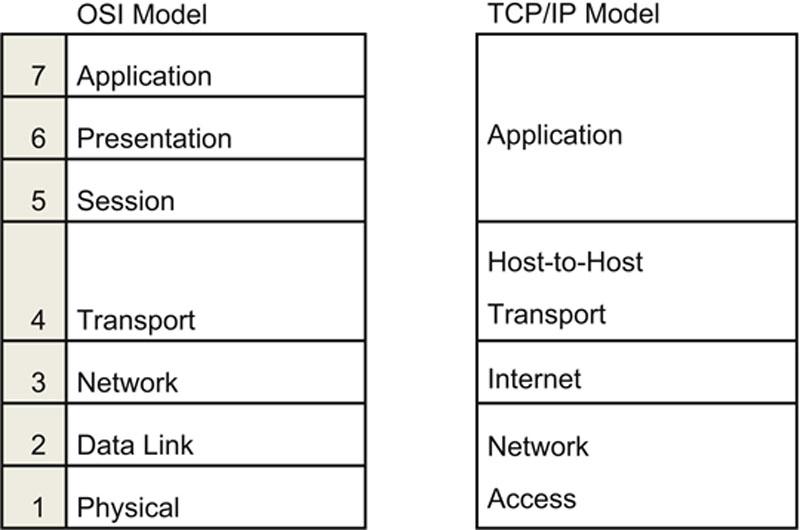
The OSI model has seven layers, as shown in Table 5.1. The layers may be listed in top-to-bottom or bottom-to-top order. Using the latter, they are Physical, Data Link, Network, Transport, Session, Presentation, and Application.
Table 5.1
The OSI Model

Layer 1 – Physical
The physical layer is layer 1 of the OSI model. Layer 1 describes units of data such as bits represented by energy (such as light, electricity, or radio waves) and the medium used to carry them (such as copper or fiber optic cables). WLANs have a physical layer, even though we cannot physically touch it.
Cabling standards such as Thinnet, Thicknet, and Unshielded Twisted Pair (UTP) exist at layer 1, among many others. Layer 1 devices include hubs and repeaters.
Layer 2 – Data Link
The Data Link Layer handles access to the physical layer as well as local area network communication. An Ethernet card and its MAC (Media Access Control) address are at Layer 2, as are switches and bridges.
Layer 2 is divided into two sub-layers: Media Access Control (MAC) and Logical Link Control (LLC). The MAC layer transfers data to and from the physical layer. LLC handles LAN communications. MAC touches Layer 1, and LLC touches Layer 3.
Layer 3 – Network
The Network layer describes routing: moving data from a system on one LAN to a system on another. IP addresses and routers exist at Layer 3. Layer 3 protocols include IPv4 and IPv6, among others.
Layer 4 – Transport
The Transport layer handles packet sequencing, flow control, and error detection. TCP and UDP are Layer 4 protocols.
Layer 4 makes a number of features available, such as resending or re-sequencing packets. Taking advantage of these features is a protocol implementation decision. As we will see later, TCP takes advantage of these features, at the expense of speed. Many of these features are not implemented in UDP, which chooses speed over reliability.
Layer 5 – Session
The Session Layer manages sessions, which provide maintenance on connections. Mounting a file share via a network requires a number of maintenance sessions, such as Remote Procedure Calls (RPCs); these exist at the session layer. A good way to remember the session layer’s function is “connections between applications.” The Session Layer uses simplex, half-duplex, and full-duplex communication.
Layer 6 – Presentation
The Presentation Layer presents data to the application (and user) in a comprehensible way. Presentation Layer concepts include data conversion, character sets such as ASCII, and image formats such as GIF (Graphics Interchange Format), JPEG (Joint Photographic Experts Group), and TIFF (Tagged Image File Format).
Layer 7 – Application
The Application Layer is where you interface with your computer application. Your Web browser, word processor, and instant messaging client exist at Layer 7. The protocols Telnet and FTP are Application Layer protocols.
The TCP/IP Model
The TCP/IP model (Transmission Control Protocol/Internet Protocol) is a popular network model created by DARPA in the 1970s (see: http://www.internetsociety.org/internet/internet-51/history-internet/brief-history-internet for more information). TCP/IP is an informal name (named after the first two protocols created); the formal name is the Internet Protocol Suite. The TCP/IP model is simpler than the OSI model, as shown in Table 5.2.
Table 5.2
The OSI Model vs. TCP/IP Model
While TCP and IP receive top billing, TCP/IP is actually a suite of protocols including UDP (User Datagram Protocol) and ICMP (Internet Control Message Protocol), among many others.
Network Access Layer
The Network Access Layer of the TCP/IP model combines layers 1 (Physical) and 2 (Data Link) of the OSI model. It describes Layer 1 issues such as energy, bits, and the medium used to carry them (copper, fiber, wireless, etc.). It also describes Layer 2 issues such as converting bits into protocol units such as Ethernet frames, MAC (Media Access Control) addresses, and Network Interface Cards (NICs).
Internet Layer
The Internet Layer of the TCP/IP model aligns with the Layer 3 (Network) layer of the OSI model. This is where IP addresses and routing live. When data is transmitted from a node on one LAN to a node on a different LAN, the Internet Layer is used. IPv4, IPv6, ICMP, and routing protocols (among others) are Internet Layer TCP/IP protocols.
Host-to-Host Transport Layer
The Host-to-Host Transport Layer (sometimes called either “Host-to-Host” or, more commonly, “Transport” alone; this book will use “Transport”) connects the Internet Layer to the Application Layer. It is where applications are addressed on a network, via ports. TCP and UDP are the two Transport Layer protocols of TCP/IP.
Application Layer
The TCP/IP Application Layer combines Layers 5 through 7 (Session, Presentation, and Application) of the OSI model. Most of these protocols use a client-server architecture, where a client (such as ssh) connects to a listening server (called a daemon on UNIX systems) such as sshd. The clients and servers use either TCP or UDP (and sometimes both) as a Transport Layer protocol. TCP/IP Application Layer protocols include SSH, Telnet and FTP, among many others.
Encapsulation
Encapsulation takes information from a higher layer and adds a header to it, treating the higher layer information as data. It is often said, “One layer’s header is another layer’s data.”[2] For example, as the data moves down the stack, application layer data is encapsulated in a layer 4 TCP segment. That TCP segment is encapsulated in a Layer 3 IP packet. That IP packet is encapsulated in a Layer 2 Ethernet frame. The frame is then converted into bits at Layer 1 and sent across the local network. Data, segments, packets, frames, and bits are examples of Protocol Data Units (PDUs).
The reverse of encapsulation is called de-multiplexing (sometimes called de- encapsulation). As the PDUs move up the stack, bits are converted to Ethernet frames, frames are converted to IP packets, packets are converted to TCP segments, and segments are converted to application data.
Network Access, Internet and Transport Layer Protocols and Concepts
TCP/IP is a protocol suite: including (but not limited to): IPv4 and IPv6 at the Internet layer; TCP and UDP at the Transport layer; and a multitude of higher-level protocols, including Telnet, FTP, SSH, and many others. Let us focus on the lower layer protocols, spanning from the Network Access to Transport layers. Some protocols, such as IP, fit neatly into one layer (Internet). Others, such as Address Resolution Protocol (ARP), help connect one layer to another (Network Access to Internet in ARP’s case).
MAC Addresses
A Media Access Control (MAC) address is the unique hardware address of an Ethernet network interface card (NIC), typically “burned in” at the factory. MAC addresses may be changed in software.
Historically, MAC addresses were 48 bits long. They have two halves: the first 24 bits form the Organizationally Unique Identifier (OUI) and the last 24 bits form a serial number (formally called an extension identifier).
Organizations that manufacture NICs, such as Cisco, Juniper, HP, IBM, and many others, purchase 24-bit OUIs from the Institute of Electrical and Electronics Engineers (IEEE), Incorporated Registration Authority. A List of registered OUIs is available at http://standards.ieee.org/regauth/oui/oui.txt
Juniper owns OUI 00-05-85, for example. Any NIC with a MAC address that begins with 00:05:85 is a Juniper NIC. Juniper can then assign MAC addresses based on their OUI: the first would have been MAC address 00:05:85:00:00:00, the second 00:05:85:00:00:01, the third 00:05:85:00:00:02, etc. This process continues until the serial numbers for that OUI have been exhausted. Then a new OUI is needed.
EUI-64 MAC addresses
The IEEE created the EUI-64 (Extended Unique Identifier) standard for 64-bit MAC addresses. The OUI is still 24 bits, but the serial number is 40 bits. This allows for far more MAC addresses, compared with 48-bit addresses. IPv6 autoconfiguration is compatible with both types of MAC addresses.
IPv4
IPv4 is Internet Protocol version 4, commonly called “IP.” It is the fundamental protocol of the Internet, designed in the 1970s to support packet-switched networking for the United States Defense Advanced Research Projects Agency (DARPA). IPv4 was used for the ARPAnet, which later became the Internet.
IP is a simple protocol, designed to carry data across networks. It is so simple that it requires a “helper protocol” called ICMP (see below). IP is connectionless and unreliable: it provides “best effort” delivery of packets. If connections or reliability are required, they must be provided by a higher-level protocol carried by IP, such as TCP.
IPv4 uses 32-bit source and destination addresses, usually shown in “dotted quad” format, such as “192.168.2.4.” A 32-bit address field allows 232, or nearly 4.3 billion, addresses. A lack of IPv4 addresses in a world where humans (and their devices) outnumber available IPv4 addresses is a fundamental problem: this was one of the factors leading to the creation of IPv6, which uses much larger 128-bit addresses.
Key IPv4 Header Fields
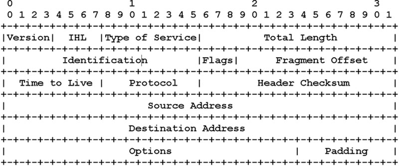
An IP header, shown in Figure 5.1, is 20 bytes long (with no options), and contains a number of fields. Key fields are:
• Version: IP version (4 for IPv4)
• IHL: Length of the IP header
• Type of Service: originally used to set the precedence of the packet, but now used for Differentiated Services (DiffServ), a method for providing Quality of Service (QoS)
• Identification, Flags, Offset: used for IP fragmentation
• Time To Live: to end routing loops
• Protocol: embedded protocol (protocol number representing TCP, UDP, etc.)
• Source and Destination IP addresses
• Optional: Options and padding
IP Fragmentation
If a packet exceeds the Maximum Transmission Unit (MTU) of a network, a router along the path may fragment it. An MTU is the maximum PDU size on a network. Fragmentation breaks a large packet into multiple smaller packets. A typical MTU size for an IP packet is 1500 bytes. The IP Identification field (IPID) is used to re-associate fragmented packets (they will have the same IPID). The flags are used to determine if fragmentation is allowed, and whether more fragments are coming. The fragment offset gives the data offset the current fragment carries: “Copy this data beginning at offset 1480.”
Path MTU discovery uses fragmentation to discover the largest size packet allowed across a network path. A large packet is sent with the DF (do not fragment) flag sent. A router with a smaller MTU than the packet size will seek to fragment, see that it cannot, and then drop it, sending a “Fragmentation needed and DF set” ICMP message. The sending node then sends increasingly smaller packets with the DF flag set, until they pass cleanly across the network path.
IPv6
IPv6 is the successor to IPv4, featuring far larger address space (128 bit addresses compared to IPv4’s 32 bits), simpler routing, and simpler address assignment. A lack of IPv4 addresses was the primary factor that led to the creation of IPv6.
IPv6 has become more prevalent since the release of the Microsoft Vista operating systems, the first Microsoft client operating system to support IPv6 and have it enabled by default. All versions through Windows 10 have done the same. Other modern operating systems, such as OS X, Linux and Unix, also enable IPv6 by default.
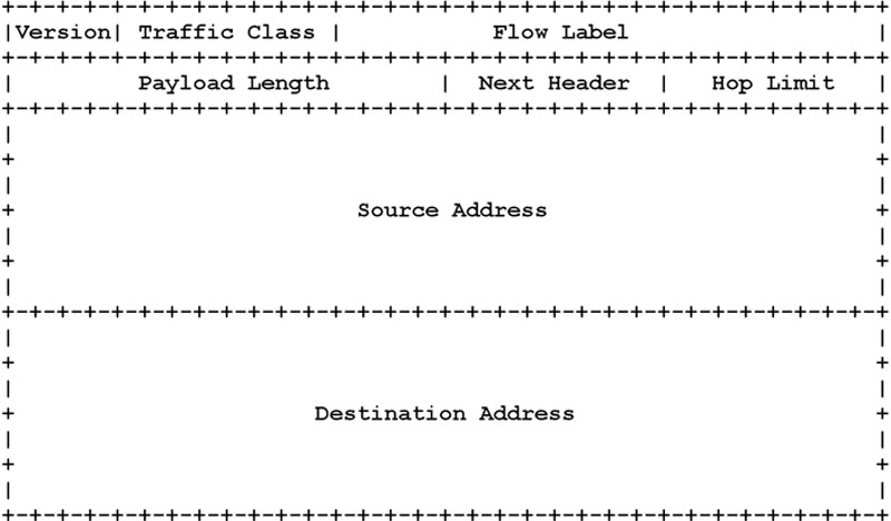
The IPv6 header, shown in Figure 5.2, is larger and simpler than IPv4. Fields include:
• Version: IP version (6 for IPv6)
• Traffic Class and Flow Label: used for QoS (Quality of Service)
• Payload Length: length of IPv6 data (not including the IPv6 header)
• Next header: next embedded protocol header
• Hop Limit: to end routing loops
IPv6 Addresses and Autoconfiguration
IPv6 hosts can statelessly autoconfigure a unique IPv6 address, omitting the need for static addressing or DHCP. IPv6 stateless autoconfiguration takes the host’s MAC address and uses it to configure the IPv6 address. The ifconfig (interface configuration) output in Figure 5.3, shows the MAC address as hardware address (HWAddr) 00:0c:29:ef:11:36.
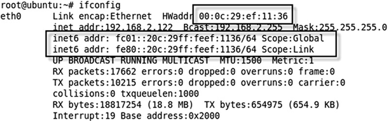
Figure 5.3 “ifconfig” Output Showing MAC address and IPv6 Addresses
IPv6 addresses are 128 bits long, and use colons instead of periods to delineate sections. One series of zeroes may be condensed into two colons (“::”). The “ifconfig” output in Figure 5.3 shows two IPv6 addresses:
• fc01::20c:29ff:feef:1136/64 (Scope:Global)
• fe80::20c:29ff:feef:1136/64 (Scope:Link)
The first address (fc01::…) is a “global” (routable) address, used for communication beyond the local network. IPv6 hosts rely on IPv6 routing advertisements to assign the global address. In Figure 5.3, a local router sent a route advertisement for the fc01 network, which the host used to configure its global address.
The second address (fe80::…) is a link-local address, used for local network communication only. Systems assign link-local addresses independently, without the need for an IPv6 router advertisement. Even without any centralized IPv6 infrastructure (such as routers sending IPv6 route advertisements), any IPv6 system will assign a link-local address, and can use that address to communicate to other link-local IPv6 addresses on the LAN.
/64 is the network size in CIDR format: see “Classless Inter-Domain Routing” section, below. This means the network prefix is 64 bits long: the full global prefix is fc01:0000:0000:0000.
The host in Figure 5.3 used the following process to statelessly configure its global address:
• Take the MAC address: 00:0c:29:ef:11:36
• Embed the “fffe” constant in the middle two bytes: 00:0c:29:ff:fe:ef:11:36
• Set the “Universal Bit”: 02:0c:29:ff:fe:ef:11:36
• Prepend the network prefix & convert to “:” format: fc01:0000:0000:0000:020c:29ff:feef:1136
• Convert one string of repeating zeroes to “::”: fc01::20c:29ff:feef:1136
This process is shown in Table 5.3.
Table 5.3
IPv6 Address Stateless Autoconfiguration

Only one consecutive series of zeroes (shown in gray in the add prefix step shown in Table 5.3) may be summarized with “::.” The “fffe” constant is added to 48-bit MAC addresses to make them 64 bits long. Support for a 64-bit embedded MAC address ensures that the stateless autoconfiguration process is compatible with EUI-64 MAC addresses. The Universal/Local (U/L) bit is used to determine whether the MAC address is unique. Our MAC is unique, so the U/L bit is set.
Stateless autoconfiguration removes the requirement for DHCP (Dynamic Host Configuration Protocol, see DHCP section below), but DHCP may be used with IPv6: this is called “stateful autoconfiguration,” part of DHCPv6. IPv6’s much larger address space also makes NAT (Network Address Translation, see NAT section below) unnecessary, but various IPv6 NAT schemes have been proposed, mainly to allow easier transition from IPv4 to IPv6.
Note that systems may be “dual stack” and use both IPv4 and IPv6 simultaneously, as Figure 5.3 shows. That system uses IPv6, and also has the IPv4 address 192.168.2.122. Hosts may also access IPv6 networks via IPv4; this is called tunneling. Another IPv6 address worth noting is the loopback address: ::1. This is equivalent to the IPv4 address of 127.0.0.1.
IPv6 Security Challenges
IPv6 solves many problems, including adding sufficient address space and autoconfiguration, making routing much simpler. Some of these solutions, such as autoconfiguration, can introduce security problems.
An IPv6-enabled system will automatically configure a link-local address (beginning with fe80:…) without the need for any other ipv6-enabled infrastructure. That host can communicate with other link-local addresses on the same LAN. This is true even if the administrators are unaware that IPv6 is now flowing on their network.
ISPs are also enabling IPv6 service, sometimes without the customer’s knowledge. Modern network tools, such as network intrusion detection systems, can “see” IPv6, but are often not configured to do so. And many network professionals have limited experience or understanding of IPv6. From an attacker’s perspective, this can offer a golden opportunity to launch attacks or exfiltrate data via IPv6.
All network services that are not required should be disabled: this is a fundamental part of system hardening. If IPv6 is not required, it should be disabled. To disable IPv6 on a Windows host, open the network adapter, and choose properties. Then uncheck the “Internet protocol Version 6” box, as shown in Figure 5.4.
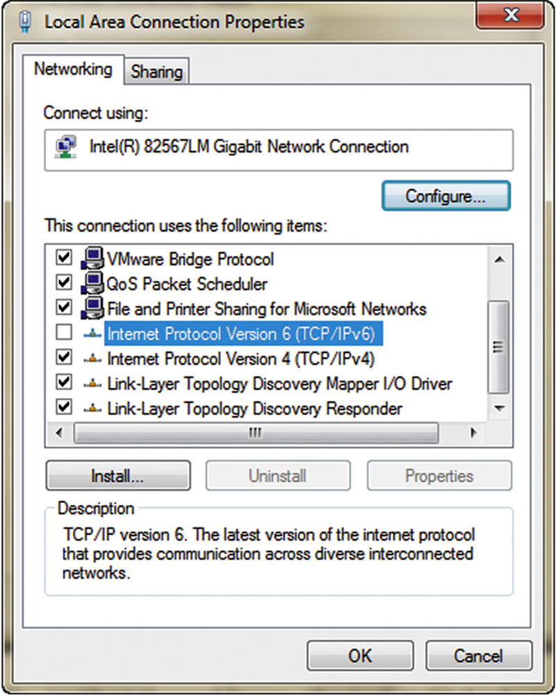
Figure 5.4 Disabling IPv6 on Windows
Classful Networks
The original IPv4 networks (before 1993) were “classful,” classified in classes A through E. Class A through C were used for normal network use. Class D was multicast, and Class E was reserved. Table 5.4 shows the IP address range of each.
Table 5.4
Classful Networks
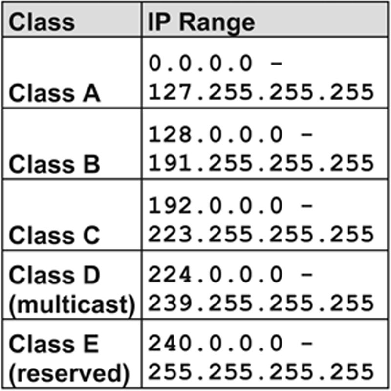
Classful networks are inflexible: networks used for normal end hosts come in three sizes: 16,777,216 addresses (Class A), 65,536 addresses (Class B), and 256 addresses (Class C). The smallest routable classful network is a Class C network with 256 addresses: a routable point-to-point link using classful networks requires a network between the two points, wasting over 250 IP addresses.
Classless Inter-Domain Routing
Classless Inter-Domain Routing (CIDR) allows far more flexible network sizes than those allowed by classful addresses. CIDR allows for many network sizes beyond the arbitrary classful network sizes.
The Class A network 10.0.0.0 contains IP addresses that begins with 10: 10.1.2.3.4, 10.187.24.8, 10.3.96.223, etc. In other words, 10.* is a Class A address. The first 8 bits of the dotted-quad IPv4 address is the network (10); the remaining 24 bits are the host address: 3.96.223 in the last previous example. The CIDR notation for a Class A network is /8 for this reason: 10.0.0.0/8. The “/8” is the netmask, which means the network portion is 8 bits long, leaving 24 bits for the host.
Similarly, the class C network of 192.0.2.0 contains any IP address that begins with 192.0.2: 192.0.2.177, 192.0.2.253, etc. That class C network is 192.0.2.0/24 in CIDR format: the first 24 bits (192.0.2) describe the network; the remaining 8 bits (177 or 253 in the previous example) describe the host.
Once networks are described in CIDR notation, additional routable network sizes are possible. Need 128 IP addresses? Chop a Class C (/24) in half, resulting in two /25 networks. Need 64 IP addresses? Chop a /24 network into quarters, resulting in four /26 networks with 64 IP addresses each.
RFC 1918 Addressing
RFC 1918 addresses are private IPv4 addresses that may be used for internal traffic that does not route via the Internet. This allows for conservation of scarce IPv4 addresses: countless intranets can use the same overlapping RFC 1918 addresses. Three blocks of IPv4 addresses are set aside for this purpose:
• 10.0.0.0-10.255.255.255 (10.0.0.0/8)
• 172.16.0.0-172.31.255.255 (172.16.0.0/12)
• 192.168.0.0-192.168.255.255 (192.168.0.0/16)
Any public Internet connection using un-translated RFC1918 addresses as a destination will fail: there are no public routes for these networks. Internet traffic sent with an un-translated RFC 1918 source address will never return. Using the classful terminology, the 10.0.0.0/8 network is a Class A network; the 172.16.0.0./12 network is 16 continuous Class B networks, and 192.168.0.0/16 is 256 Class C networks.
RFC 1918 addresses are used to conserve public IPv4 addresses, which are in short supply. RFC stands for “Request for Comments,” a way to discuss and publish standards on the Internet. More information about RFC 1918 is available at: http://www.rfc-editor.org/rfc/rfc1918.txt.
Network Address Translation
Network Address Translation (NAT) is used to translate IP addresses. It is frequently used to translate RFC1918 addresses as they pass from intranets to the Internet. If you were wondering how you could surf the public Web using a PC configured with a private RFC 1918 address, NAT is one answer (proxying is another).
Three types of NAT are static NAT, pool NAT (also known as dynamic NAT), and Port Address Translation (PAT, also known as NAT overloading). Static NAT makes a one-to-one translation between addresses, such as 192.168.1.47→192.0.2.252. Pool NAT reserves a number of public IP addresses in a pool, such as 192.0.2.10→192.0.2.19. Addresses can be assigned from the pool, and then returned. Finally, PAT typically makes a many-to-one translation from multiple private addresses to one public IP address, such as 192.168.1.* to 192.0.2.20. PAT is a common solution for homes and small offices: multiple internal devices such as laptops, desktops and mobile devices share one public IP address. Table 5.5 summarizes examples of the NAT types.
Table 5.5
Types of NAT

NAT hides the origin of a packet: the source address is the NAT gateway (usually a router or a firewall), not of the host itself. This provides some limited security benefits: an attack against a system’s NAT-translated address will often target the NAT gateway, and not the end host. This protection is limited, and should never be considered a primary security control. Defense-in-depth is always required.
NAT can cause problems with applications and protocols that change IP addresses or contain IP addresses in upper layers, such as the data layer of TCP/IP. IPsec, VoIP, and active FTP are among affected protocols.
ARP and RARP
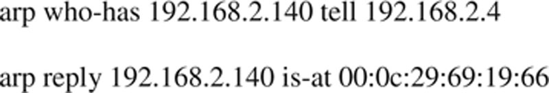
ARP is the Address Resolution Protocol, used to translate between Layer 2 MAC addresses and Layer 3 IP addresses. ARP resolves IPs to MAC addresses by asking, “Who has IP address 192.168.2.140, tell me.” An example of an ARP reply is “192.168.2.140 is at 00:0c:29:69:19:66.”
RARP is used by diskless workstations to determine its IP address. A node asks “Who has MAC address at 00:40:96:29:06:51, tell 00:40:96:29:06:51.

In other words RARP asks: “Who am I? Tell me.” A RARP server answers with the node’s IP address.
Unicast, Multicast, and Broadcast Traffic
Unicast is one-to-one traffic, such as a client surfing the Web. Multicast is one-to-many, and the “many” is preselected. Broadcast is one-to-all on a LAN.
Multicast traffic uses “Class D” addresses when used over IPv4. Nodes are placed into multicast groups. A common multicast application is streaming audio or video. Sending 1000 audio streams via unicast would require a large amount of bandwidth, so multicast is used. It works like a tree: the initial stream is the trunk, and each member of the multicast group a leaf. One stream is sent from the streaming server, and it branches on the network as it reaches routers with multiple routes for nodes in the multicast group. Multicast typically uses UDP.
Limited and Directed Broadcast addresses
Broadcast traffic is sent to all stations on a LAN. There are two types of IPv4 broadcast addresses: limited broadcast and directed broadcast. The limited broadcast address is 255.255.255.255. It is “limited” because it is never forwarded across a router, unlike a directed broadcast.
The directed (also called net-directed) broadcast address of the 192.0.2.0/24 network is 192.0.2.255 (the host portion of the address is all “1”s in binary, or 255). It is called “directed” broadcast, because traffic to these addresses may be sent from remote networks (it may be “directed”).
Layer 2 Broadcast Traffic
Layer 2 broadcast traffic reaches all nodes in a “broadcast domain.” Devices on the same LAN (or VLAN) are in the same broadcast domain. The Ethernet broadcast address is MAC address “FF:FF:FF:FF:FF:FF”: traffic sent to that address on an Ethernet switch is received by all connected nodes.
Promiscuous Network Access
Accessing all unicast traffic on a network segment requires “promiscuous” network access. Systems such as Network Intrusion Detection Systems (NIDS) require promiscuous network access in order to monitor all traffic on a network. Network nodes normally only “see” unicast traffic sent directly to them. Accessing unicast traffic sent to other nodes requires two things: a network interface card (NIC) configured in promiscuous mode, and the ability to access other unicast traffic on a network segment.
Placing a NIC in promiscuous mode normally requires super-user access, such as the root user on a UNIX system. Devices such as switches provide traffic isolation, so that each host will only receive unicast traffic sent to it (in addition to broadcast and multicast traffic). As we will see in a later section, a hub, switch SPAN port, or TAP is typically used to provide promiscuous network access.
TCP
TCP is the Transmission Control Protocol, a reliable Layer 4 protocol. TCP uses a three-way handshake to create reliable connections across a network. TCP can reorder segments that arrive out of order, and retransmit missing segments.
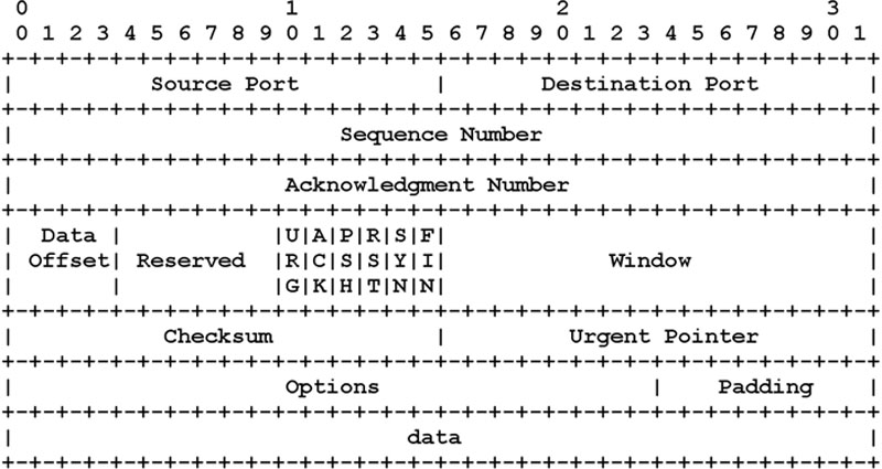
Key TCP Header Fields
A TCP header, shown in Figure 5.5, is 20 bytes long (with no options), and contains a number of fields. Important fields include:
• Source and Destination port
• Sequence and Acknowledgment Numbers: Keep full-duplex communication in sync
• TCP Flags
• Window Size: Amount of data that may be sent before receiving acknowledgment
TCP ports
TCP connects from a source port to a destination port, such as from source port 51178 to destination port 22. The TCP port field is 16 bits, allowing port numbers from 0 to 65535.
There are two types of ports: reserved and ephemeral. A reserved port is 1023 or lower; ephemeral ports are 1024-65535. Most operating systems require super-user privileges to open a reserved port. Any user may open an (unused) ephemeral port.
Common services such as HTTP use well-known ports. The Internet Assigned Numbers Authority (IANA) maintains a list of well-known ports at http://www.iana.org/assignments/port-numbers. Most Linux and UNIX systems have a smaller list of well-known ports in /etc/services.
Socket Pairs
A socket is a combination of an IP address and a TCP or UDP port on one node. A socket pair describes a unique connection between two nodes: source port, source IP, destination port, and destination IP. The netstat output in Figure 5.6 shows a socket pair between source IP 192.168.80.144, TCP source port 51178, and destination IP 192.168.2.4, destination TCP port 22.
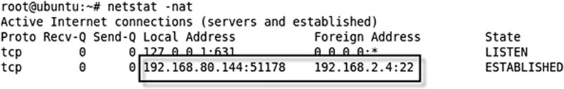
Figure 5.6 TCP Socket Pair
A socket may “listen” (wait for a connection); a listening socket is shown as 127.0.0.1:631 in Figure 5.6. A socket pair is then “established” during a connection. You may have multiple connections from the same host (such as 192.168.80.144), to the same host (192.168.2.4), and even to the same port (22). The OS and intermediary devices such as routers are able to keep these connections unique due to the socket pairs. In the previous example, two connections from the same source IP and to the same IP/destination port would have different source ports, making the socket pairs (and connections) unique.
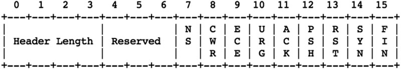
TCP Flags
The original six TCP flags are:
• URG: Packet contains urgent data
• ACK: Acknowledge received data
• PSH: Push data to application layer
• RST: Reset (tear down) a connection
• SYN: Synchronize a connection
• FIN: Finish a connection (gracefully)
Two new TCP flags were added in 2001: CWR (Congestion Window Reduced) and ECE (Explicit Congestion Notification Echo), using formerly reserved bits in the TCP header. A third new flag was added in 2003: NS (Nonce Sum). These flags are used to manage congestion (slowness) along a network path. All 9 TCP flags are shown in Figure 5.7.
The TCP handshake
TCP uses a three-way handshake to establish a reliable connection. The connection is full duplex, and both sides synchronize (SYN) and acknowledge (ACK) each other. The exchange of these four flags is performed in three steps: SYN, SYN-ACK, ACK, as shown in Figure 5.8.

Figure 5.8 TCP Three-Way Handshake
The client chooses an initial sequence number, set in the first SYN packet. The server also chooses its own initial sequence number, set in the SYN/ACK packet shown in Figure 5.8. Each side acknowledges each other’s sequence number by incrementing it: this is the acknowledgement number. The use of sequence and acknowledgement numbers allows both sides to detect missing or out-of-order segments.
Once a connection is established, ACKs typically follow for each segment. The connection will eventually end with a RST (reset or tear down the connection) or FIN (gracefully end the connection).
UDP
UDP is the User Datagram Protocol, a simpler and faster cousin to TCP. UDP has no handshake, session, or reliability: it is informally called “Send and Pray” for this reason. UDP has a simpler and shorter 8-byte header (shown in Figure 5.9), compared to TCP’s default header size of 20 bytes. UDP header fields include source port, destination port, packet length (header and data), and a simple (and optional) checksum. If used, the checksum provides limited integrity to the UDP header and data. Unlike TCP, data usually is transferred immediately, in the first UDP packet. UDP operates at Layer 4.
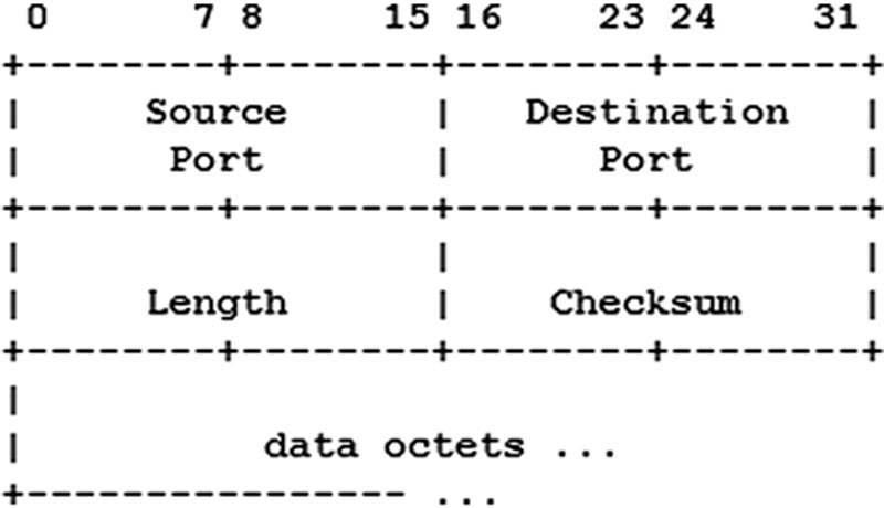
UDP is commonly used for applications that are “lossy” (can handle some packet loss), such as streaming audio and video. It is also used for query-response applications, such as DNS queries.
ICMP
ICMP is the Internet Control Message Protocol, a helper protocol that helps Layer 3 (IP, see note). ICMP is used to troubleshoot and report error conditions: Without ICMP to help, IP would fail when faced with routing loops, ports, hosts, or networks that are down, etc. ICMP has no concept of ports, as TCP and UDP do, but instead uses types and codes. Commonly used ICMP types are echo request and echo reply (used for ping) and time to live exceeded in transit (used for traceroute).
Ping
Ping (named after sonar used to “ping” submarines) sends an ICMP Echo Request to a node and listens for an ICMP Echo Reply. Ping was designed to determine whether a node is up or down.
Ping was a reliable indicator of a node’s status on the ARPAnet or older Internet, when firewalls were uncommon (or did not exist). Today, an ICMP Echo Reply is a fairly reliable indicator that a node is up. Attackers use ICMP to map target networks, so many sites filter types of ICMP such as Echo Request and Echo Reply.
An unanswered ping (an ICMP Echo Request with no Echo Reply) does not mean a host is down. The node may be down, or the node may be up and the Echo Request or Echo Reply may have been filtered at some point.
Traceroute
The traceroute command uses ICMP Time Exceeded messages to trace a network route. As discussed during IP, the Time to Live field is used to avoid routing loops: every time a packet passes through a router, the router decrements the TTL field. If the TTL reaches zero, the router drops the packet and sends an ICMP Time Exceeded message to the original sender.
Traceroute takes advantage of this TTL feature in a clever way. Assume a client is four hops away from a server: the client’s traceroute client sends a packet to the server with a TTL of 1. The router A decrements the TTL to 0, drops the packet, and sends an ICMP Time Exceeded message to the client. Router A is now identified.
The client then sends a packet with a TTL of 2 to the server. Router A decrements the TTL to 1 and passes the packet to router B. Router B decrements the TTL to 0, drops it, and sends an ICMP Time Exceeded message to the client. Router B is now identified. This process continues until the server is reached, as shown in Figure 5.10, identifying all routers along the route.
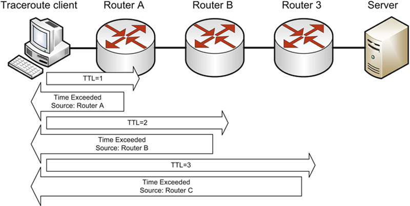
Figure 5.10 Traceroute
Most traceroute clients (such as UNIX and Cisco) send UDP packets outbound. The outbound packets will be dropped, so the protocol does not matter. The Windows tracert client sends ICMP packets outbound; Figure 5.11 shows Windows tracert output for a route to www.syngress.com. Both client types usually send three packets for each hop (the three “ms” columns in the Figure 5.11 output).

Application Layer TCP/IP Protocols and Concepts
A multitude of protocols exist at TCP/IP’s Application Layer, which combines the Session, Presentation, and Application Layers of the OSI model.
Telnet
Telnet provides terminal emulation over a network. “Terminal” means text-based VT100-style terminal access. Telnet servers listen on TCP port 23. Telnet was the standard way to access an interactive command shell over a network for over 20 years.
Telnet is weak because it provides no confidentiality; all data transmitted during a telnet session is plaintext, including the username and password used to authenticate to the system. Attackers who are able to sniff network traffic can steal authentication credentials this way.
Telnet also has limited integrity: attackers with write access to a network can alter data, or even seize control of Telnet sessions. Secure Shell (SSH) provides secure authentication, confidentiality, and integrity and is a recommended replacement for Telnet.
FTP
FTP is the File Transfer Protocol, used to transfer files to and from servers. Like Telnet, FTP has no confidentiality or integrity and should not be used to transfer sensitive data over insecure channels.
FTP uses two ports: the control connection (where commands are sent) is TCP port 21; “Active FTP” uses a data connection (where data is transferred) that originates from TCP port 20. Here are the two socket pairs (the next two examples use arbitrary ephemeral ports):
• Client:1025→Server:21 (Control Connection)
• Server:20→Client: 1026 (Data Connection)
Notice that the data connection originates from the server, in the opposite direction of the control channel. This breaks classic client-server data flow direction. Many firewalls will block the active FTP data connection for this reason, breaking Active FTP. Passive FTP addresses this issue by keeping all communication from client to server:
• Client:1025→Server:21 (Control Connection)
• Client 1026→Server:1025 (Data Connection)
The FTP server tells the client which listening data connection port to connect to; the client then makes a second connection. Passive FTP is more likely to pass through firewalls cleanly, since it flows in classic client-server direction.
TFTP
TFTP is the Trivial File Transfer Protocol, which runs on UDP port 69. It provides a simpler way to transfer files and is often used for saving router configurations or “bootstrapping” (downloading an operating system) via a network by diskless workstations.
TFTP has no authentication or directory structure: files are read from and written to one directory, usually called /tftpboot. There is also no confidentiality or integrity. Like Telnet and FTP, TFTP is not recommended for transferring sensitive data over an insecure channel.
SSH
SSH was designed as a secure replacement for Telnet, FTP, and the UNIX “R” commands (rlogin, rshell, etc). It provides confidentiality, integrity, and secure authentication, among other features. SSH includes SFTP (SSH FTP) and SCP (Secure Copy) for transferring files. SSH can also be used to securely tunnel other protocols, such as HTTP. SSH servers listen on TCP port 22 by default.
SSH version 1 was the original version, which has since been found vulnerable to man-in-the middle attacks. SSH version 2 is the current version of the protocol, and is recommended over SSHv1, or Telnet, FTP, etc.
SMTP, POP and IMAP
SMTP is the Simple Mail Transfer Protocol, used to transfer email between servers. SMTP servers listen on TCP port 25. POPv3 (Post Office Protocol) and IMAP (Internet Message Access Protocol) are used for client-server email access, which use TCP ports 110 and 143, respectively.
DNS
DNS is the Domain Name System, a distributed global hierarchical database that translates names to IP addresses, and vice versa. DNS uses both TCP and UDP: small answers use UDP port 53; large answers (such as zone transfers) use TCP port 53.
Two core DNS functions are gethostbyname() and gethostbyaddr(). Given a name (such as www.syngress.com), gethostbyname returns an IP address, such as 192.0.2.187. Given an address such as 192.0.2.187, gethostbyaddr returns the name, www.syngress.com.
Authoritative name servers provide the “authoritative” resolution for names within a given domain. A recursive name server will attempt to resolve names that it does not already know. A caching name server will temporarily cache names previously resolved.
DNS Weaknesses
DNS uses the unreliable UDP protocol for most requests, and native DNS provides no authentication. The security of DNS relies on a 16-bit source port and 16-bit DNS query ID. Attackers who are able to blindly guess both numbers can forge UDP DNS responses.
A DNS cache poisoning attack is an attempt to trick a caching DNS server into caching a forged response. If bank.example.com is at 192.0.2.193, and evil.example.com is at 198.18.8.17, an attacker may try to poison a DNS server’s cache by sending the forged response of “bank.example.com is at 198.18.8.17.” If the caching DNS name server accepts the bogus response, it will respond with the poisoned response for subsequent bank.example.com requests (until the record expires).
DNSSEC
DNSSEC (Domain Name Server Security Extensions) provides authentication and integrity to DNS responses via the use of public key encryption. Note that DNSSEC does not provide confidentiality: it acts like a digital signature for DNS responses.
Building an Internet-scale Public Key Infrastructure is a difficult task, and DNSSEC has been slowly adopted for this reason. Security researcher Dan Kaminsky publicized an improved DNS cache poisoning attack in 2008, which has led to renewed calls for wider adoption of DNSSEC. See http://www.kb.cert.org/vuls/id/800113 for more details on the improved cache poisoning attack and defenses.
SNMP
SNMP is the Simple Network Management Protocol, primarily used to monitor network devices. Network monitoring software such as HP OpenView and MRTG use SNMP to poll SNMP agents on network devices, and report interface status (up/down), bandwidth utilization, CPU temperature, and many more metrics. SNMP agents use UDP port 161.
SNMPv1 and v2c use read and write community strings to access network devices. Many devices use default community strings such as “public” for read access, and “private” for write access. Additionally, these community strings are usually changed infrequently (if at all), and are typically sent in the clear across a network. An attacker who can sniff or guess a community string can access the network device via SNMP. Access to a write string allows remote changes to a device, including shutting down or reconfiguring interfaces, among many other options.
SNMPv3 was designed to provide confidentiality, integrity, and authentication to SNMP via the use of encryption. While SNMPv2c usage remains highly prevalent, use of SNMPv3 is strongly encouraged due to the lack of security in all previous versions.
HTTP and HTTPS
HTTP is the Hypertext Transfer Protocol, which is used to transfer unencrypted Web-based data. HTTPS (Hypertext Transfer Protocol Secure) transfers encrypted Web-based data via SSL/TLS (see SSL/TLS section, below). HTTP uses TCP port 80, and HTTPS uses TCP port 443. HTML (Hypertext Markup Language) is used to display Web content.
BOOTP and DHCP
BOOTP is the Bootstrap Protocol, used for bootstrapping via a network by diskless systems. Many system BIOSs now support BOOTP directly, allowing the BIOS to load the operating system via a network without a disk. BOOTP startup occurs in two phases: use BOOTP to determine the IP address and OS image name, and then use TFTP to download the operating system.
DHCP (Dynamic Host Configuration Protocol) was designed to replace and improve on BOOTP by adding additional features. DHCP allows more configuration options, as well as assigning temporary IP address leases to systems. DHCP systems can be configured to receive IP address leases, DNS servers, and default gateways, among other information.
Both BOOTP and DHCP use the same ports: UDP port 67 for servers and UDP port 68 for clients.
Layer 1 Network Cabling
The simplest part of the OSI model is the part you can touch: network cables, at Layer 1. It is important to understand the types of cabling that are commonly used, and the benefits and drawbacks of each.
Fundamental network cabling terms to understand include EMI, noise, crosstalk, and attenuation. Electro Magnetic Interference (EMI) is interference caused by magnetism created by electricity. Any unwanted signal (such as EMI) on a network cable is called noise. Crosstalk occurs when a signal crosses from one cable to another. Attenuation is the weakening of signal as it travels further from the source.
Twisted Pair Cabling
Unshielded Twisted Pair (UTP) network cabling, shown in Figure 5.12, uses pairs of wire twisted together. All electricity creates magnetism; taking two wires that send electricity in opposite direction (such as sending and receiving) and twisting them together dampens the magnetism. This makes Twisted Pair cabling less susceptible to EMI.
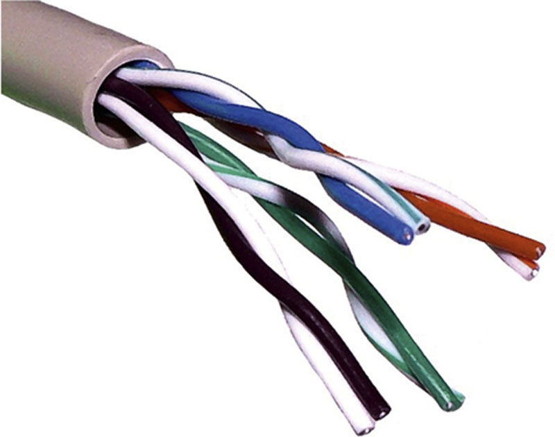
Figure 5.12 UTP Cable Source: http://upload.wikimedia.org/wikipedia/commons/c/cb/UTP_cable.jpg. Image by Baran Ivo. Image under permission of Creative Commons
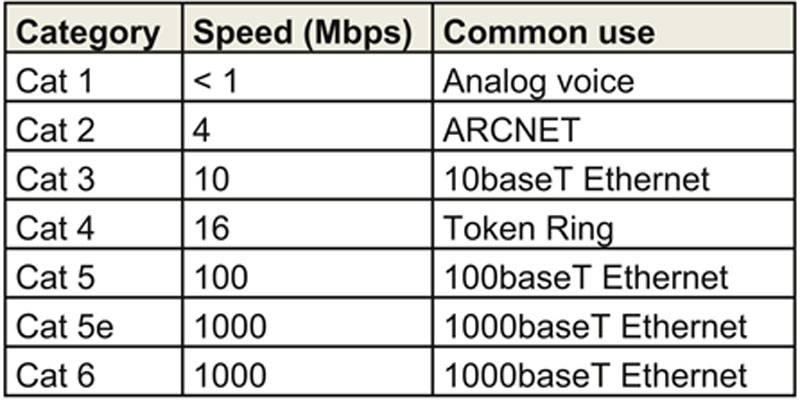
Twisted pair cables are classified by categories according to rated speed. Tighter twisting results in more dampening: a Category 6 UTP cable designed for gigabit networking has far tighter twisting than a Category 3 fast Ethernet cable. Table 5.6 summarizes the types and speeds of Category cabling. Cisco Press also has a good summary at http://www.ciscopress.com/articles/article.asp?p=31276.
Table 5.6
Category Cabling Speed and Usage
Shielded Twisted Pair (STP) contains additional metallic shielding around each pair of wires. This makes STP cables less susceptible to EMI, but more rigid and more expensive.
Coaxial Cabling
A coaxial network cable, shown in Figure 5.13, has an inner copper core (marked “D”) separated by an insulator (marked “C”) from a metallic braid or shield (marked “B”). The outer layer is a plastic sheath (marked “A”). The insulator prevents the core from touching the metallic shield, which would create an electrical short. Coaxial cables are often used for satellite and cable TV service.

Figure 5.13 Coaxial Cable Source: http://commons.wikimedia.org/wiki/File:RG-59.jpg.Image by Arj. Image under permission of Creative Commons
The core and shield used by coaxial cable are thicker and better insulated than other cable types, such as twisted pair. This makes coaxial more resistant to EMI and allows higher bandwidth and longer connections compared with twisted pair cable.
Two older types of coaxial cable are Thinnet and Thicknet, used for Ethernet bus networking.
Fiber Optic Network Cable
Fiber Optic network cable (simply called “fiber”) uses light to carry information, which can carry a tremendous amount of information. Fiber can be used to transmit via long distances: past 50 miles, much further than any copper cable such as twisted pair or coaxial. Fiber’s advantages are speed, distance, and immunity to EMI. Disadvantages include cost and complexity.
Multimode fiber carrier uses multiple modes (paths) of light, resulting in light dispersion. Single-mode fiber uses a single strand of fiber, and the light uses one mode (path) down the center of the fiber. Multimode fiber is used for shorter distances; single-mode fiber is used for long haul, high-speed networking.
Multiple signals may be carried via the same fiber via the use of Wavelength Division Multiplexing (WDM), where multiple light “colors” are used to transmit different channels of information via the same fiber. Combined speeds of over a terabit/second can be achieved when WDM is used to carry 10-gigabits per color.
LAN Technologies and Protocols
Local Area Network concepts focus on layer 1-3 technologies such as network cabling types, physical and logical network topologies, Ethernet, FDDI, and others.
Ethernet
Ethernet is a dominant local area networking technology that transmits network data via frames. It originally used a physical bus topology, but later added support for physical star. Ethernet describes Layer 1 issues such as physical medium and Layer 2 issues such as frames. Ethernet is baseband (one channel), so it must address issues such as collisions, where two nodes attempt to transmit data simultaneously.
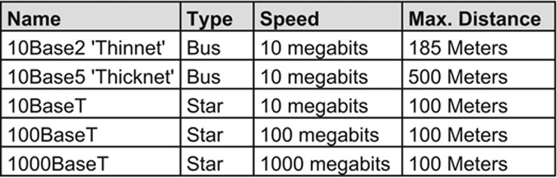
Ethernet has evolved from 10-megabit buses that used “thinnet” or “thicknet” coaxial cable. The star-based physical layer uses Twisted Pair cables that range in speed from 10 megabits to 1000 megabits and beyond. A summary of these types is listed in Table 5.7.
Table 5.7
Types of Ethernet
CSMA
Carrier Sense Multiple Access (CSMA) is designed to address collisions. Ethernet is baseband media, which is the equivalent of a “party line.” In the early days of phone service, many people did not have a dedicated phone line for their house: they shared a party line with their neighbors. A protocol emerged for using the shared phone line:
1. Lift the receiver and listen to determine if the line is idle
2. If the line is not idle, hang up and wait before trying again
3. If the line is idle, dial
Ethernet CSMA works in the same fashion, but there is one state that has not been accounted for: two neighbors lift their receivers and listen to hear if the line is in use. Hearing nothing, both dial simultaneously. Their calls “collide”: the integrity of their calls is ruined. CSMA is designed to address collisions.
Carrier Sense Multiple Access with Collision Detection (CSMA/CD) is used to immediately detect collisions within a network. It takes the following steps:
1. Monitor the network to see if it is idle
2. If the network is not idle, wait a random amount of time
3. If the network is idle, transmit
4. While transmitting, monitor the network
5. If more electricity is received than sent, another station must also be sending
a. Send Jam signal to tell all nodes to stop transmitting
b. Wait a random amount of time before retransmitting
CSMA/CD is used for systems that can send and receive simultaneously, such as wired Ethernet. CSMA/CA (Collision Avoidance) is used for systems such as 802.11 wireless that cannot send and receive simultaneously. CSMA/CA relies on receiving an acknowledgement from the receiving station: if no acknowledgement is received, there must have been a collision, and the node will wait and retransmit. CSMA/CD is superior to CSMA/CA because collision detection detects a collision almost immediately.
ARCNET & Token Ring
ARCNET (Attached Resource Computer Network) and Token Ring are two legacy LAN technologies. Both pass network traffic via tokens. Possession of a token allows a node to read or write traffic on a network. This solves the collision issue faced by Ethernet: nodes cannot transmit without a token.
ARCNET ran at 2.5 megabits and popularized the star topology (later copied by Ethernet). The last version of Token Ring ran at 16 megabits, using a physical star that passed tokens in a logical ring.
Both Token Ring and ARCNET are deterministic (not random), unlike Ethernet. Both have no collisions, which (among other factors) leads to predictable network behavior. Many felt Token Ring was superior to Ethernet (when Ethernet’s top speed was 10 megabits). Ethernet was cheaper and ultimately faster than Token Ring, and ended up becoming the dominant LAN technology.
FDDI
FDDI (Fiber Distributed Data Interface) is another legacy LAN technology, running a logical network ring via a primary and secondary counter-rotating fiber optic ring. The secondary ring was typically used for fault tolerance. A single FDDI ring runs at 100 megabits. FDDI uses a “token bus,” a different token-passing mechanism than Token Ring.
In addition to reliability, another advantage of FDDI is light: fiber cable is not affected by electromagnetic interference (EMI).
LAN Physical Network Topologies
Physical Network Topologies describe Layer 1 locally: how the cables are physically run. There have been many popular physical topologies over the years; many, such as the bus and ring, have faded as the star topology has become dominant.
Bus
A physical bus connects network nodes in a string, as shown in Figure 5.14. Each node inspects the data as it passes along the bus.

Figure 5.14 Bus
Network buses are fragile: should the network cable break anywhere along the bus; the entire bus would go down. For example, if the cable between Node A and Node B should break in Figure 5.14, the entire bus would go down, including the connection between Node B and C. A single defective NIC can also impact an entire bus.
Tree
A tree is also called hierarchical network: a network with a root node, and branch nodes that are at least three levels deep (two levels would make it a star). The root node controls all tree traffic, as shown in Figure 5.15. The tree is a legacy network design; the root node was often a mainframe.
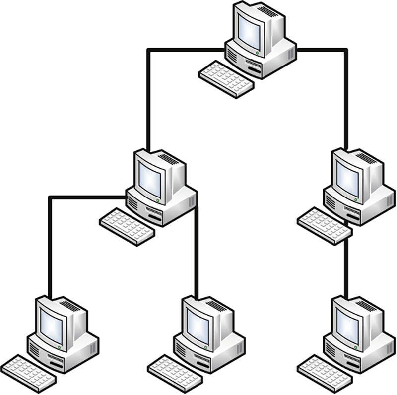
Figure 5.15 Tree Topology
Ring
A physical ring connects network nodes in a ring: if you follow the cable from node to node, you will finish where you began, as shown in Figure 5.16.
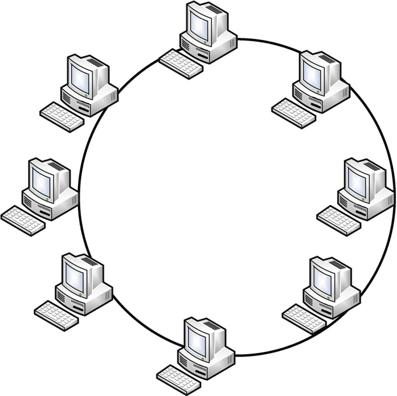
Figure 5.16 Ring Topology
Star
Star topology has become the dominant physical topology for LANs. The star was first popularized by ARCNET, and later adopted by Ethernet. Each node is connected directly to a central device such as a hub or a switch, as shown in Figure 5.17.
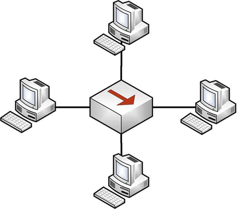
Figure 5.17 Star Topology
Stars feature better fault tolerance: any single local cable cut or NIC failure affects one node only. Since each node is wired back to a central point, more cable is required as opposed to bus (where one cable run connects nodes to each other). This cost disadvantage is usually outweighed by the fault tolerance advantages.
Mesh
A mesh interconnects network nodes to each other. Figure 5.18 shows two mesh networks. The left mesh is fully connected, with four Web servers interconnected. The right mesh is partially connected: each node has multiple connections to the mesh, but every node does not connect to every other.
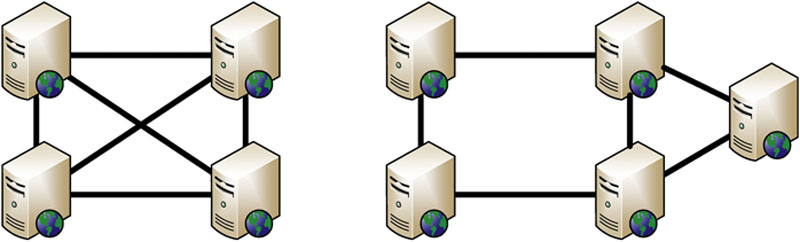
Figure 5.18 Fully Connected and Partially Connected Mesh Topologies
Meshes have superior availability and are often used for highly available (HA) server clusters. Each of the four Web servers shown on the left in Figure 5.18 can share the load of Web traffic, and maintain state information between each other. If any web server in the mesh goes down, the others remain up to shoulder the traffic load.
WAN Technologies and Protocols
ISPs and other “long-haul” network providers, whose networks span from cities to countries, often use wide Area Network technologies. Many of us have hands-on experience configuring LAN technologies such as connecting Cat5 network cabling; it is less common to have hands-on experience building WANs.
T1s, T3s, E1s, E3s
There are a number of international circuit standards: the most prevalent are T Carriers (United States) and E Carriers (Europe). A T1 is a dedicated 1.544-megabit circuit that carries twenty-four 64-bit DS0 (Digital Signal 0) channels (such as 24 circuit-switched phone calls). Note that the terms DS1 (Digital Signal 1) and T1 are often used interchangeably. DS1 describes the flow of bits (via any medium, such as copper, fiber, wireless, etc.); a T1 is a copper telephone circuit that carries a DS1.
A T3 is 28 bundled T1s, forming a 44.736-megabit circuit. The terms T3 and DS3 (Digital Signal 3) are also used interchangeably, with the same T1/DS1 distinction noted above. E1s are dedicated 2.048-megabit circuits that carry 30 channels, and 16 E1s form an E3, at 34.368 megabits.
SONET (Synchronous Optical Networking) carries multiple T-carrier circuits via fiber optic cable. SONET uses a physical fiber ring for redundancy.
Frame Relay
Frame Relay is a packet-switched Layer 2 WAN protocol that provides no error recovery and focuses on speed. Higher layer protocols carried by Frame Relay, such as TCP/IP can be used to provide reliability.
Frame Relay multiplexes multiple logical connections over a single physical connection to create Virtual Circuits; this shared bandwidth model is an alternative to dedicated circuits such as T1s. A PVC (Permanent Virtual Circuit) is always connected, analogous to a real dedicated circuit like a T1. A Switched Virtual Circuit (SVC) sets up each “call,” transfers data, and terminates the connection after an idle timeout. Frame Relay is addressed locally via Data Link Connection Identifiers (DLCI, pronounced “delsee”).
X.25
X.25 is an older packet-switched WAN protocol. X.25 provided a cost-effective way to transmit data over long distances in the 1970s through early 1990s, when the most common other option was a direct call via analog modem. X.25’s popularity has faded as the Internet has become ubiquitous.
The global packet switched X.25 network is separate from the global IP-based Internet. X.25 performs error correction that can add latency on long links. It can carry other protocols such as TCP/IP, but since TCP provides its own reliability, there is no need to take the extra performance hit by also providing reliability at the X.25 layer. Other protocols such as frame relay are usually used to carry TCP/IP.
ATM
Asynchronous Transfer Mode (ATM) is a WAN technology that uses fixed length cells. ATM cells are 53 bytes long, with a 5-byte header and 48-byte data portion.
ATM allows reliable network throughput compared to Ethernet. The answer to “How many Ethernet frames can I send per second” is “It depends.” Normal Ethernet frames can range in size from under 100 bytes to over 1500 bytes. In contrast, all ATM cells are 53 bytes.
SMDS (Switched Multimegabit Data Service) is older and similar to ATM, also using 53-byte cells.
MPLS
Multiprotocol Label Switching (MPLS) provides a way to forward WAN data via labels, via a shared MPLS cloud network. This allows MPLS networks to carry many types of network traffic, including ATM, Frame relay, IP, and others. Decisions are based on labels, and not encapsulated header data (such as an IP header). MPLS can carry voice and data, and be used to simplify WAN routing: assume 12 offices connect to a data center. If T1s were used, the data center would require 12 T1 circuits (one to each office); with MPLS, the data center and each office would require a single connection to connect to the MPLS cloud.
SDLC and HDLC
Synchronous Data Link Control (SDLC) is a synchronous Layer 2 WAN protocol that uses polling to transmit data. Polling is similar to token passing; the difference is a primary node polls secondary nodes, which can transmit data when polled. Combined nodes can act as primary or secondary. SDLC supports NRM transmission only (see below).
High-Level Data Link Control (HDLC) is the successor to SDLC. HDLC adds error correction and flow control, as well as two additional modes (ARM and ABM). The three modes of HDLC are:
• Normal Response Mode (NRM)—Secondary nodes can transmit when given permission by the primary
• Asynchronous Response Mode (ARM)—Secondary nodes may initiate communication with the primary
• Asynchronous Balanced Mode (ABM)—Combined mode where nodes may act as primary or secondary, initiating transmissions without receiving permission
Converged Protocols
“Convergence” is a recent network buzzword. It means providing services such as industrial controls, storage and voice (that were typically delivered via non-IP devices and networks) via Ethernet and TCP/IP.
DNP3
The Distributed Network Protocol (DNP3) provides an open standard used primarily within the energy sector for interoperability between various vendors’ SCADA and smart grid applications. According to the US Department of Energy, “Smart grid” generally refers to a class of technology people are using to bring utility electricity delivery systems into the 21st century, using computer-based remote control and automation. These systems are made possible by two-way communication technology and computer processing that has been used for decades in other industries. They are beginning to be used on electricity networks, from the power plants and wind farms all the way to the consumers of electricity in homes and businesses. They offer many benefits to utilities and consumers – mostly seen in big improvements in energy efficiency on the electricity grid and in the energy users’ homes and offices. [8]
Some protocols, such as SMTP, fit into one layer. DNP3 is a multilayer protocol and may be carried via TCP/IP (another multilayer protocol): “Many vendors offer products that operate using TCP/IP to transport DNP3 messages in lieu of the media discussed above. Link layer frames, which we have not talked about yet, are embedded into TCP/IP packets. This approach has enabled DNP3 to take advantage of Internet technology and permitted economical data collection and control between widely separated devices.” [9]
Recent improvements in DNP3 allow for “Secure Authentication,” which addresses challenges with the original specification that could have allowed, for example, spoofing or replay attacks. DNP3 became an IEEE standard in 2010, called IEEE 1815-2010 (now deprecated). It allowed pre-shared keys only. IEEE 1815-2012 is the current standard; it supports Public Key Infrastructure (PKI).
Storage Protocols
Fibre Channel over Ethernet (FCoE) and Internet Small Computer System Interface (iSCSI) are both Storage Area Network (SAN) protocols that provide cost-effective ways to leverage existing network infrastructure technologies and protocols to interface with storage. A Storage Area Network allows block-level file access across a network, just like a directly attached hard drive. Note that fibre channel uses the Canadian/UK spelling of “fibre,” while fiber optic cable typically uses the American spelling of “fiber.”
FCoE leverages Fibre Channel, which has long been used for storage networking, but dispenses with the requirement for completely different cabling and hardware. Instead, FCoE can be transmitted across standard Ethernet networks. In FCoE, Fibre Channel’s HBA (Host Bus Adapters), which historically were unique cards to interface with storage, can be combined with the network interface (NIC), for economies of scale. FCoE uses Ethernet, but not TCP/IP. Fibre Channel over IP (FCIP) encapsulates Fibre Channel frames via TCP/IP.
Like FCoE, iSCSI is a SAN protocol that allows for leveraging existing networking infrastructure and protocols to interface with storage. While FCoE simply uses Ethernet, iSCSI makes use of higher layers of the TCP/IP suite for communication, and can be routed like any IP protocol (the same is true for FCIP). By employing protocols beyond layer 2 (Ethernet), iSCSI can be transmitted beyond just the local network. Thus, iSCSI could even allow for accessing storage that resides across a WAN. iSCSI uses Logical Unit Numbers (LUNs) to provide a way of addressing storage across the network. LUNs can also be used for basic access control for network accessible storage.
Virtual SAN
Storage Area Networks have historically tended to be rather proprietary and used dedicated hardware and protocols that did not easily interoperate. Though many SAN implementations now leverage protocols such as FCoE, FCIP, or iSCSI that can allow for converged traditional networking technologies and protocols, the scalability and security of the Storage Area Networking has often proven cumbersome.
Traditional approaches to storage security often required hard-coding changes at switches or the HBAs to achieve access control. One approach to a virtual SAN feels analogous to the switching concept of VLANs and tries to allow for a conceptually simplistic approach to isolation within the SAN. This concept of the virtual SAN as analogous to VLANs is most commonly employed by networking vendors.
The concept of a virtual SAN is not limited to simply security considerations from networking vendors. Much recent use of the term virtual SAN leans heavily on the virtual side of the phrase. Virtualization vendors employ the term virtual SAN to imply an approach to the SAN that allows for more rapid provisioning of virtualized storage. Beyond provisioning, virtualization vendors tout the virtual SAN as a means to leverage virtualization to afford simpler linear scalability to the storage area network.
VoIP
Voice over Internet Protocol (VoIP) carries voice via data networks, a fundamental change from analog POTS (Plain Old Telephone Service), which remains in use after over 100 years. VoIP brings the advantages of packet-switched networks, such as lower cost and resiliency, to the telephone.
Recently, many organizations have maintained at least two distinct networks: a phone network and a data network, each with associated maintenance costs. The reliability of packet-switched data networks has grown as organizations have made substantial investments. With the advent of VoIP, many organizations have lowered costs by combining voice and data services on packet-switched networks.
Common VoIP protocols include Real-time Transport Protocol (RTP), designed to carry streaming audio and video. VoIP protocols such as RTP rely upon session and signaling protocols including SIP (Session Initiation Protocol, a signaling protocol) and H.323. SRTP (Secure Real-time Transport Protocol) may be used to provide secure VoIP, including confidentiality, integrity, and secure authentication. SRTP uses AES for confidentiality and SHA-1 for integrity.
While VoIP can provide compelling cost advantages (especially for new sites, without a large legacy voice investment), there are security concerns. If the network goes down, both voice and network data go down. Also, there is no longer a true “out of band” channel for wired voice. If an attacker has compromised a network, they may be able to compromise the confidentiality or integrity of the VoIP calls on that network. Many VoIP protocols, such as RTP, provide little or no security by default. In that case, eavesdropping on a VoIP call is as simple as sniffing with a tool like Wireshark (a high-quality free network protocol analyzer, see http://www.wireshark.org), selecting the “Telephony → VoIP Calls” menu, choosing a call and pressing “Player,” as shown in Figure 5.19.
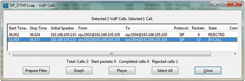
Figure 5.19 Wireshark “VoIP Calls”
Organizations that deploy VoIP must ensure reliability by making sufficient investments in their data networks, and in staff expertise required to support them. In the event of network compromise, use other methods such as cell phones for out-of-band communication. Finally, any VoIP traffic sent via insecure networks should be secured via SRTP, or other methods such as IPsec. Never assume VoIP traffic is secure by default.
Software-Defined Networks
Through virtualization and cloud services, storage and compute are increasingly decoupled from the traditional server and disk-dense datacenter. Software-defined networking (SDN) seeks a similar paradigm shift on organizations’ approach to networking. A helpful oversimplification can be to think of SDN as an approach to virtualize networking and decouple networking from the hardware typically employed for this purpose.
Software Defined Networking (SDN) separates a router’s control plane from the data (forwarding) plane. The control plane makes routing decisions. The data plane forwards data (packets) through the router. With SDN routing decisions are made remotely, instead of on each individual router.
One of the primary goals of SDN is to allow for nimble and customizable networking capabilities. A hallmark of SDN is the potential for achieving this flexibility using inexpensive “white-box” networking hardware and open protocols rather than traditional proprietary hardware, firmware, and software. Another common goal with SDN is to accommodate dynamic instantiation of networking capabilities rules as they become needed within the infrastructure.
The most well-known protocol in this space is OpenFlow, which can, among other capabilities, allow for control of switching rules to be designated or updated at a central controller. OpenFlow is a TCP protocol that uses TLS encryption.
Wireless Local Area Networks
Wireless Local Area Networks (WLANs) transmit information via electromagnetic waves (such as radio) or light. Historically, wireless data networks have been very insecure, often relying on the (perceived) difficulty in attacking the confidentiality or integrity of the traffic. This perception is usually misplaced. The most common form of wireless data networking is the 802.11 wireless standard, and the first 802.11 standard that provides reasonable security is 802.11i.
DoS & Availability
WLANs have no way to assure availability. An attacker with physical proximity can launch a variety of Denial-of-Service attacks, including simply polluting the wireless spectrum with noise. If you think of the CIA triad as a three-legged stool, “wireless security” is missing a leg. Critical applications that require a reliable network should use wired connections.
Unlicensed Bands
A “band” is a small amount of contiguous radio spectrum. Industrial, Scientific, and Medical (ISM) bands are set aside for unlicensed use, meaning you do not need to acquire a license from an organization such as the Federal Communications Commission (FCC) to use them. Many wireless devices such as cordless phones, 802.11 wireless, and Bluetooth use ISM bands. Different countries use different ISM bands: two popular ISM bands used internationally are 2.4 and 5 GHz.
FHSS, DSSS and OFDM
Frequency Hopping Spread Spectrum (FHSS) and Direct Sequence Spread Spectrum (DSSS) are two methods for sending traffic via a radio band. Some bands, like the 2.4-GHz ISM band, can be quite polluted with interference: Bluetooth, some cordless phones, some 802.11 wireless, baby monitors, and even microwaves can broadcast or interfere with this band. Both DSSS and FHSS are designed to maximize throughput while minimizing the effects of interference.
DSSS uses the entire band at once, “spreading” the signal throughout the band. FHSS uses a number of small frequency channels throughout the band and “hops” through them in pseudorandom order.
Orthogonal Frequency-Division Multiplexing (OFDM) is a newer multiplexing method, allowing simultaneous transmission using multiple independent wireless frequencies that do not interfere with each other.
802.11
802.11 wireless has many standards, using various frequencies and speeds. The original mode is simply called 802.11 (sometimes 802.11-1997, based on the year it was created), which operated at 2 megabits per second (Mbps) using the 2.4 GHz frequency; it was quickly supplanted by 802.11b, at 11 Mbps. 802.11g was designed to be backwards compatible with 802.11b devices, offering speeds up to 54 Mbps using the 2.4 GHz frequency. 802.11a offers the same top speed, using the 5 GHz frequency.
802.11n uses both 2.4 and 5 GHz frequencies, and is able to use multiple antennas with multiple-input multiple-output (MIMO). This allows speeds up to 600 Mbps. Finally, 802.11ac uses the 5 GHz frequency only, offering speeds up to 1.3 Gbps. Table 5.8 summarizes the major types of 802.11 wireless.
Table 5.8
Types of 802.11 Wireless
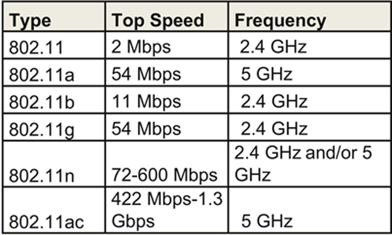
The 2.4 GHz frequency can be quite crowded: some cordless phones and baby monitors use that frequency, as does Bluetooth and some other wireless devices. Microwave ovens can interfere with 2.4 GHz devices. The 5 GHz frequency is usually less crowded, and often has less interference than 2.4 GHz. As 5 GHz is a higher frequency with shorter waves, it does not penetrate walls and other obstructions as well as the longer 2.4 GHz waves.
Managed, Master, Ad-Hoc and Monitor modes
802.11 wireless NICs can operate in four modes: managed, master, ad hoc, and monitor mode.
802.11 wireless clients connect to an access point in managed mode (also called client mode). Once connected, clients communicate with the access point only; they cannot directly communicate with other clients.
Master mode (also called infrastructure mode) is the mode used by wireless access points. A wireless card in master mode can only communicate with connected clients in managed mode.
Ad hoc mode is a peer-to-peer mode with no central access point. A computer connected to the Internet via a wired NIC may advertise an ad hoc WLAN to allow Internet sharing.
Finally, monitor mode is a read-only mode used for sniffing WLANs. Wireless sniffing tools like Kismet or Wellenreiter use monitor mode to read all 802.11 wireless frames.
SSID and MAC Address Filtering
802.11 WLANs use a Service Set Identifier (SSID), which acts as a network name. Wireless clients must know the SSID before joining that WLAN, so the SSID is a configuration parameter. SSIDs are normally broadcasted; some WLANs are configured to disable SSID broadcasts, as a security feature. Relying on the secrecy of the SSID is a poor security strategy: a wireless sniffer in monitor mode can detect the SSID used by clients as they join WLANs; this is true even if SSID broadcasts are disabled.
Another common 802.11 wireless security precaution is restricting client access by filtering the wireless MAC address, allowing only trusted clients. This provides limited security. MAC addresses are exposed in plaintext on 802.11 WLANs; trusted MACs can be sniffed, and an attacker may reconfigure a non-trusted device with a trusted MAC address in software. Then the attacker can wait for the trusted device to leave the network (or launch a DoS against the trusted device), and join the network with a trusted MAC address.
WEP
WEP is the Wired Equivalent Privacy protocol, an early attempt (first ratified in 1999) to provide 802.11 wireless security. WEP has proven to be critically weak: new attacks can break any WEP key in minutes. Due to these attacks, WEP effectively provides little integrity or confidentiality protection. WEP is considered broken and its use is strongly discouraged. The encryption algorithms specified in 802.11i and/or other encryption methods such as VPN should be used in place of WEP.
WEP was designed at a time when exportation of encryption was more regulated than it is today, and was designed specifically to avoid conflicts with existing munitions laws (see Chapter 4, Domain 3: Security Engineering for more information about such laws). In other words, WEP was designed to be “not too strong,” cryptographically, and it turned out to be even weaker than anticipated. WEP has 40 and 104-bit key lengths, and uses the RC4 cipher. WEP frames have no timestamp and no replay protection: attackers can inject traffic by replaying previously sniffed WEP frames.
802.11i
802.11i is the first 802.11 wireless security standard that provides reasonable security. 802.11i describes a Robust Security Network (RSN), which allows pluggable authentication modules. RSN allows changes to cryptographic ciphers as new vulnerabilities are discovered.
RSN is commonly referred to as WPA2 (Wi-Fi Protected Access 2), a full implementation of 802.11i. By default, WPA2 uses AES encryption to provide confidentiality, and CCMP (Counter Mode CBC MAC Protocol) to create a Message Integrity Check (MIC), which provides integrity. The less secure WPA (without the “2”) was designed for access points that lack the power to implement the full 802.11i standard, providing a better security alternative to WEP. WPA uses RC4 for confidentiality and TKIP for integrity. Usage of WPA2 is recommended over WPA.
Bluetooth
Bluetooth, described by IEEE standard 802.15, is a Personal Area Network (PAN) wireless technology, operating in the same 2.4 GHz frequency as many types of 802.11 wireless devices. Bluetooth can be used by small low-power devices such as cell phones to transmit data over short distances. Bluetooth versions 2.1 and older operate at 3 Mbps or less; Versions 3 (announced in 2009) and higher offer far faster speeds.
Bluetooth has three classes of devices, summarized below. Although Bluetooth is designed for short-distance networking, it is worth noting that class 1 devices can transmit up to 100 meters.
• Class 3: under 10 meters
• Class 2: 10 meters
• Class 1: 100 meters
Bluetooth uses the 128-bit E0 symmetric stream cipher. Cryptanalysis of E0 has proven it to be weak; practical attacks show the true strength to be 38 bits or less.
Sensitive devices should disable automatic discovery by other Bluetooth devices. The “security” of discovery relies on the secrecy of the 48-bit MAC address of the Bluetooth adapter. Even when disabled, Bluetooth devices may be discovered by guessing the MAC address. The first 24 bits are the OUI, which may be easily guessed; the last 24 bits may be determined via brute-force attack. For example, many Nokia phones use the OUI of 00:02:EE. If an attacker knows that a target device is a Nokia phone, the remaining challenge is guessing the last 24 bits of the MAC address.
RFID
Radio Frequency Identification (RFID) is a technology used to create wirelessly readable tags for animals or objects. There are three types of RFID tags: Active, semi-passive, and passive. Active and semi-passive RFID tags have a battery. An active tag broadcasts a signal; semi-passive RFID tags rely on a RFID reader’s signal for power. Passive RFID tags have no battery, and also rely on the RFID reader’s signal for power.
Active RFID tags can operate via larger distances. Devices like toll transponders (allowing automatic payment of highway tolls) use active tags. Passive RFID tags are less expensive; they are used for applications such as tracking inventory in a warehouse.
RFID signals may be blocked with a Faraday Cage, which shields enclosed objects from EMI. Electricity will seek to go around a conductive object rather than through it (like lightning hitting a car: the occupants inside are usually unharmed). A Faraday Cage is a metal cage or enclosure that acts as the conductive object, protecting objects inside. This blocks many radio signals, including RFID.
The cage can be as simple as aluminum foil wrapped around an object. Instructions for building a Faraday Cage wallet (designed to protect smart cards with RFID chips) from aluminum foil and duct tape are available at: http://howto.wired.com/wiki/Make_a_Faraday_Cage_Wallet.
Secure Network Devices and Protocols
Let us look at network devices ranging from Layer 1 hubs through Application-Layer Proxy firewalls that operate up to Layer 7. Many of these network devices, such as routers, have protocols dedicated to their use, such as routing protocols.
Repeaters and Hubs
Repeaters and hubs are layer 1 devices. A repeater receives bits on one port, and “repeats” them out the other port. The repeater has no understanding of protocols; it simply repeats bits. Repeaters are often used to extend the length of a network.
A hub is a repeater with more than two ports. It receives bits on one port and repeats them across all other ports.
Hubs were quite common before switches became common and inexpensive. Hubs provide no traffic isolation and have no security: all nodes see all traffic sent by the hub. Hubs provide no confidentiality or integrity; an attacker connected to hub may read and potentially alter traffic sent via the hub.
Hubs are also half-duplex devices: they cannot send and receive simultaneously. Any device connected to a hub will negotiate to half duplex mode, which can cause network congestion. Hubs also have one “collision domain”: any node may send colliding traffic with another (for more information on collisions, see previous “CSMA” section).
The lack of security, half duplex mode, and large collision domain make hubs unsuitable for most modern purposes. One exception is network forensics: hubs may be used to provide promiscuous access for a forensic investigator. Other options, like TAPs and Switch SPAN ports (see below), are usually a better choice.
Bridges
Bridges and switches are Layer 2 devices. A bridge has two ports, and connects network segments together. Each segment typically has multiple nodes, and the bridge learns the MAC addresses of nodes on either side. Traffic sent from two nodes on the same side of the bridge will not be forwarded across the bridge. Traffic sent from a node on one side of the bridge to the other side will forward across. The bridge provides traffic isolation and makes forwarding decisions by learning the MAC addresses of connected nodes.
In Figure 5.20, traffic sent from Computer 1 to Computer 2 will not forward across the bridge. Traffic sent from Computer 1 to Computer 3 will be forwarded across the bridge.

Figure 5.20 Network Bridge
A bridge has two collision domains. A network protocol analyzer (informally called a “sniffer”) on the right side of the network shown in Figure 5.20 can sniff traffic sent to or from Computers 3 and 4, but not sniff Computer 1 or 2 traffic (unless sent to Computers 3 or 4).
Switches
A switch is a bridge with more than two ports. Also, it is best practice to only connect one device per switch port. Otherwise, everything that is true about a bridge is also true about a switch.
Figure 5.21 shows a network switch. The switch provides traffic isolation by associating the MAC address of each computer and server with its port. Traffic sent between Computer 1 and Server 1 remains isolated to their switch ports only: a network sniffer running on Server 3 will not see that traffic.
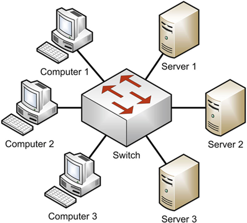
Figure 5.21 Network Switch
A switch shrinks the collision domain to a single port. You will normally have no collisions assuming one device is connected per port (which is best practice).
Trunks are used to connect multiple switches.
VLANs
A VLAN is a Virtual LAN, which can be thought of as a virtual switch. In Figure 5.21, imagine you would like to create a computer LAN and a server LAN. One option is to buy a second switch, and dedicate one for computers and one for servers.
Another option is to create a VLAN on the original switch, as shown in Figure 5.22. That switch has two VLANs, and acts as two virtual switches: a computer switch and a server switch.
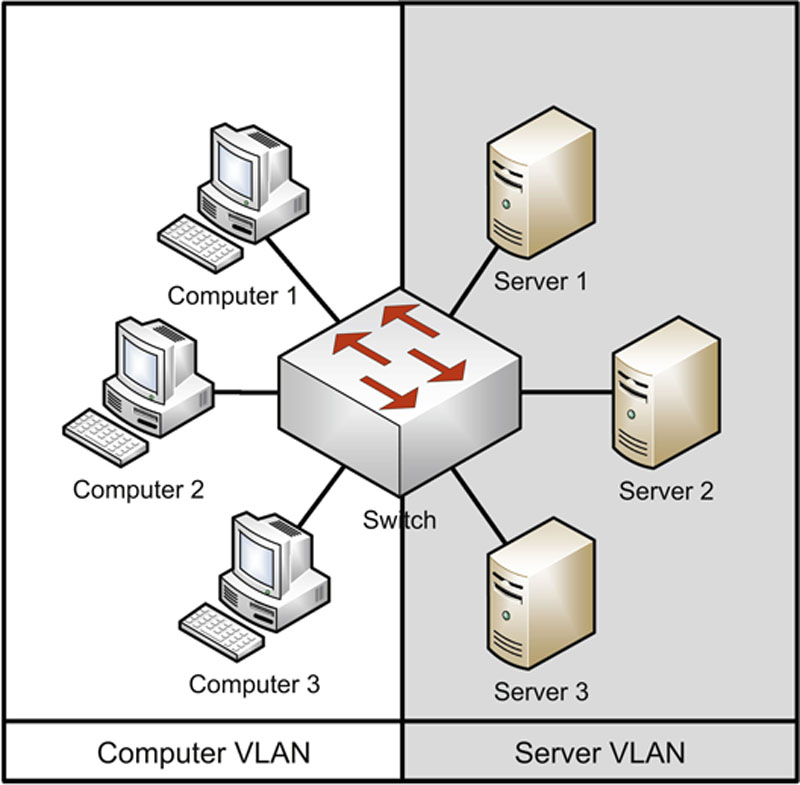
Figure 5.22 Switch VLAN
The VLAN in Figure 5.22 has two broadcast domains. Traffic sent to MAC address FF:FF:FF:FF:FF:FF by computers 1-3 will reach the other computers, but not the servers on the Server VLAN. Inter-VLAN communication requires layer 3 routing, discussed in the next section.
VLANs may also add defense-in-depth protection to networks; for example, using VLANs to segment data and management network traffic.
Port Isolation
The concept of port isolation is not new, but has been revitalized and more commonly employed with the increasing density of virtualized systems in datacenters. Traditional port isolation focused on using software in a managed switch to isolate a port such that it could only communicate to the designated uplink. This port isolation, also commonly referred to as a Private VLAN or PVLAN, can be used to ensure that individual systems cannot interact with other resources even if logically on the same subnet. From a security standpoint this could severely limit the ability of an adversary to pivot or move laterally within an organization after successfully compromising a system.
Architecturally, implementing widespread traditional port isolation/PVLANs has seemed to prove cumbersome for many organizations. However, with heavily virtualized infrastructures, port isolation has found a resurgence. Port isolation can prove tremendously useful in multi-tenant environments to help ensure isolation amongst customers being serviced by the same hypervisor. Likewise, even in internal virtual infrastructures, there are often systems that have no need of direct access to one another, but are fronted by the same hypervisor. Port isolation can help to ensure logical segmentation even within a single vswitch (virtual switch).
SPAN ports
Since switches provide traffic isolation, a Network Intrusion Detection System (NIDS) connected to a 24-port switch will not see unicast traffic sent to and from other devices on the same switch. Configuring a Switched Port Analyzer (SPAN) port is one way to solve this problem, by mirroring traffic from multiple switch ports to one “SPAN port.” SPAN is a Cisco term; HP switches use the term “Mirror port.”
One drawback to using a switch SPAN port is port bandwidth overload. A 100-megabit, 24-port switch can mirror twenty-three 100-megabit streams of traffic to a 100-megabit SPAN port. The aggregate traffic could easily exceed 100 megabits, meaning the SPAN port (and connected NIDS) will miss traffic.
Network Taps
A network tap provides a way to “tap” into network traffic, and see all traffic (including all unicast connections) on a network. Taps are the preferred way to provide promiscuous network access to a sniffer or Network Intrusion Detection System.
Taps can “fail open,” so that network traffic will pass in the event of a failure. Taps can also provide access to all traffic, including malformed Ethernet frames. A switch will often “clean” that traffic and not pass it. Finally, Taps can be purchased with memory buffers, which cache traffic bursts.
Routers
Routers are Layer 3 devices that route traffic from one LAN to another. IP-based routers make routing decisions based on the source and destination IP addresses.
Static and Default Routes
For simple routing needs, static routes may suffice. Static routes are fixed routing entries, saying “The route for network 10.0.0.0/8 routes via router 192.168.2.7; the route for network 172.16.0.0/12 routes via router 192.168.2.8,” etc. Most SOHO (Small Office/Home Office) routers have a static “default route” that sends all external traffic to one router (typically controlled by the ISP).
Here is an example of a typical home LAN network configuration:
• Internal network: 192.168.1.0/24
• Internal Firewall IP: 192.168.1.1
• External Network: 192.0.2.0/30
• External Firewall IP: 192.0.2.2
• Next hop address: 192.0.2.1
The firewall has an internal and external interface, with IP addresses of 192.168.1.1 and 192.0.2.2, respectively. Internal (trusted) hosts receive addresses on the 192.168.1.0/24 subnet via DHCP. Internet traffic is NAT-translated to the external firewall IP of 192.0.2.2. The static default route for internal hosts is 192.168.1.1. The default external route is 192.0.2.1. This is a router owned and controlled by the ISP.
Routing Protocols
Static routes work fine for simple networks with limited or no redundancy, like SOHO networks. More complex networks with many routers and multiple possible paths between networks have more complicated routing needs.
The network in Figure 5.23 has redundant paths between all four sites. Should any single circuit or site go down, at least one alternate path is available. The fastest circuits are the 45-megabit T3s that connect the data center to each office. Additional 1.5 megabit T1s connect Office A to B, and B to C.

Figure 5.23 Redundant Network Architecture
Should the left-most T3 circuit go down, between the Data Center and Office A, there are multiple paths available from the data center to Office A: the fastest is the T3 to Office B, and then the T1 to Office A.
You could use static routes for this network, preferring the faster T3s over the slower T1s. The problem: what happens if a T3 goes down? Network engineers like to say that all circuits go down…eventually. Static routes would require manual reconfiguration.
Routing protocols are the answer. The goals of routing protocols are to automatically learn a network topology, and learn the best routes between all network points. Should a best route go down, backup routes should be chosen, and chosen quickly. And ideally this should happen, even while the network engineers are asleep.
Convergence means that all routers on a network agree on the state of routing. A network that has had no recent outages is normally “converged”: all routers see all routes as available. Then a circuit goes down. The routers closest to the outage will know right away; routers that are further away will not. The network now lacks convergence: some routers believe all circuits are up, while others know one is down. A goal of routing protocols is to make convergence time as fast as possible.
Routing protocols come in two basic varieties: Interior Gateway Protocols (IGPs), like RIP and OSPF, and Exterior Gateway Protocols (EGPs), like BGP. Private networks like Intranets use IGPs, and EGPs are used on public networks like the Internet. Routing protocols support Layer 3 (Network) of the OSI model.
Distance Vector Routing Protocols
Metrics are used to determine the “best” route across a network. The simplest metric is hop count. In Figure 5.23, the hop count from the data center to each office via T3 is 1. Additional paths are available from the data center to each office, such as the T3 to Office B, followed by the T1 to Office A.
The latter route is two hops, and the second hop is via a slower T1. Any network engineer would prefer the single-hop T3 connection from the data center to Office A, instead of the two-hop detour via Office B to Office A. And all routing protocols would do the same, choosing the one-hop T3.
Things get trickier when you consider connections between the offices. How should traffic route from Office A to B? The shortest hop count is via the direct T1. But that link only has 1.5 megabits: taking the two-hop route from Office A down to the data center and back up to Office B offers 45 megabits, at the expense of an extra hop.
A distance vector routing protocol such as RIP would choose the direct T1 connection, and consider one hop at 1.5 megabits “faster” than two hops at 45 megabits. Most Network Engineers (and all Link state routing protocols, as described in the next section) would disagree.
Distance vector routing protocols use simple metrics such as hop count, and are prone to routing loops, where packets loop between two routers. The following output is a Linux traceroute of a routing loop, starting between hops 16 and 17. The nyc and bos core routers will keep forwarding the packets back and forth between each other, each believing the other has the correct route.
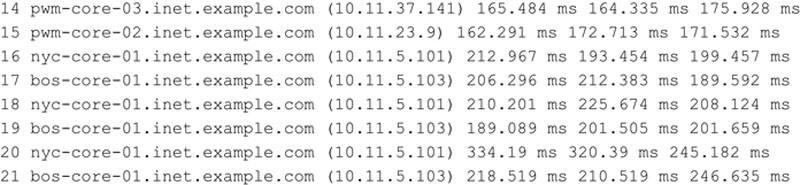
RIP
RIP (Routing Information Protocol) is a distance vector routing protocol that uses hop count as its metric. RIP will route traffic from Office A to Office B in Figure 5.23 via the direct T1, since it is the “closest” route at 1 hop.
RIP does not have a full view of a network: it can only “see” directly connected routers. Convergence is slow. RIP sends routing updates every 30 seconds, regardless of routing changes. RIP routers that are on a network that is converged for weeks will send routing updates every 30 seconds, around the clock.
RIP’s maximum hop count is 15; 16 is considered “infinite.” RIPv1 can route classful networks only; RIPv2 added support for CIDR. RIP is used by the UNIX routed command, and is the only routing protocol universally supported by UNIX.
RIP uses split horizon to help avoid routing loops. In Figure 5.24, the circuit between the NYC and BOS routers has gone down. At that moment, the NYC and BOS routers know the circuit is down; the other routers do not. The network lacks convergence.

Figure 5.24 Sample Network with Down Circuit
NYC tells the PWM router “The route between NYC and BOS is down.” On PWM’s other interface, the ATL router may claim that the link is up. Split horizon means the PWM router will not “argue back”: it will not send a route update via an interface it learned the route from. In our case, the PWM router will not send a NYC→BOS routing update to the NYC router. Poison reverse is an addition to Split Horizon: instead of sending nothing to NYC regarding the NYC→BOS route, PWM sends NYC a NYC→BOS route with a cost of 16 (infinite). NYC will ignore any “infinite” route.
RIP uses a hold-down timer to avoid “flapping” (repeatedly changing a route’s status from up to down). Once RIP changes a route’s status to “down,” RIP will “hold” to that decision for 180 seconds. In Figure 5.24, the PWM router will keep the NYC→BOS route “down” for 180 seconds. The hope is that the network will have reached convergence during that time. If not, after 180 seconds, RIP may change the status again.
RIP is quite limited. Each router has a partial view of the network and each sends updates every 30 seconds, regardless of change. Convergence is slow. Hold-down timers, Split Horizon, and Poison Reverse are small fixes that do not compensate for RIP’s weaknesses. Link State routing protocols such as OSPF are superior.
Link State Routing Protocols
Link state routing protocols factor in additional metrics for determining the best route, including bandwidth. A link state protocol would see multiple routes from Office A to Office B in Figure 5.23, including the direct T1 link, and the 2-hop T3 route via the data center. The additional bandwidth (45 via 1.5 megabits) would make the two T3 route the winner.
OSPF
Open Shortest Path First (OSPF) is an open link state routing protocol. OSPF routers learn the entire network topology for their “area” (the portion of the network they maintain routes for, usually the entire network for small networks). OSPF routers send event-driven updates. If a network is converged for a week, the OSPF routers will send no updates. OSPF has far faster convergence than distance vector protocols such as RIP. In Figure 5.23, OSPF would choose the two T3 route from Office A to B, over the single-hop T1 route.
BGP
BGP is the Border Gateway Protocol, the routing protocol used on the Internet. BGP routes between autonomous systems, which are networks with multiple Internet connections. BGP has some distance vector properties, but is formally considered a path vector routing protocol.
Firewalls
Firewalls filter traffic between networks. TCP/IP packet filter and stateful firewalls make decisions based on layers 3 and 4 (IP addresses and ports). Proxy firewalls can also make decisions based on layers 5–7. Firewalls are multi-homed: they have multiple NICs connected to multiple different networks.
Packet Filter
A packet filter is a simple and fast firewall. It has no concept of “state”: each filtering decision must be made on the basis of a single packet. There is no way to refer to past packets to make current decisions.
The lack of state makes packet filter firewalls less secure, especially for sessionless protocols like UDP and ICMP. In order to allow ping via a firewall, both ICMP Echo Requests and Echo Replies must be allowed, independently: the firewall cannot match a previous request with a current reply. All Echo Replies are usually allowed, based on the assumption that there must have been a previous matching Echo Request.
The packet filtering firewall shown in Figure 5.25 allows outbound ICMP echo requests and inbound ICMP echo replies. Computer 1 can ping bank.example.com. The problem: an attacker at evil.example.com can send unsolicited echo replies, which the firewall will allow.

Figure 5.25 Packet Filter Firewall Design
UDP-based protocols suffer similar problems. DNS uses UDP port 53 for small queries, so packet filters typically allow all UDP DNS replies on the assumption that there must have been a previous matching request.
Stateful Firewalls
Stateful firewalls have a state table that allows the firewall to compare current packets to previous ones. Stateful firewalls are slower than packet filters, but are far more secure.
Computer 1 sends an ICMP Echo Request to bank.example.com in Figure 5.26. The firewall is configured to allow ping to Internet sites, so the stateful firewall allows the traffic, and adds an entry to it state table.

Figure 5.26 Stateful Firewall Design
An Echo Reply is then received from bank.example.com to Computer 1 in Figure 5.26. The firewall checks to see if it allows this traffic (it does), and then checks the state table for a matching echo request in the opposite direction. The firewall finds the matching entry, deletes it from the state table, and passes the traffic.
Then evil.example.com sends an unsolicited ICMP Echo Reply. The stateful firewall, shown in Figure 5.26, sees no matching state table entry, and denies the traffic.
Proxy Firewalls
Proxies are firewalls that act as intermediary servers. Both packet filter and stateful firewalls pass traffic through or deny it: they are another hop along the route. The TCP 3-way handshake occurs from the client to the server, and is passed along by packet filter or stateful firewalls.
Proxies terminate connections. Figure 5.27 shows the difference between TCP Web traffic from Computer 1 to bank.example.com passing via a stateful firewall and a proxy firewall. The stateful firewall passes one TCP three-way handshake between Computer 1 and bank.example.com. A packet filter will do the same.
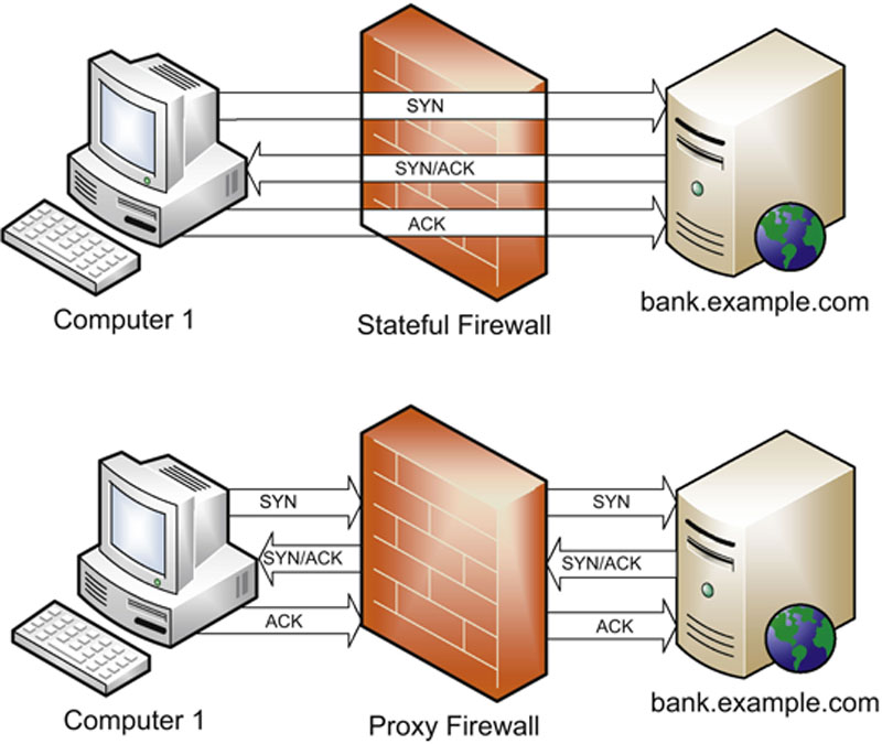
Figure 5.27 Stateful vs. Proxy Firewalls
The proxy firewall terminates the TCP connection from Computer 1, and initiates a TCP connection with bank.example.com. In this case, there are two handshakes: Computer 1 → Proxy, and Proxy → bank.example.com.
Like NAT, a proxy hides the origin of a connection. In the lower half of Figure 5.27, the source IP address connecting to bank.example.com belongs to the firewall, not Computer 1.
Application-Layer Proxy Firewalls
Application-layer proxy firewalls operate up to Layer 7. Unlike packet filter and stateful firewalls that make decisions based on layers 3 and 4 only, application-layer proxies can make filtering decisions based on application-layer data, such as HTTP traffic, in addition to layers 3 and 4.
Application-layer proxies must understand the protocol that is proxied, so dedicated proxies are often required for each protocol: an FTP proxy for FTP traffic, an HTTP proxy for Web traffic, etc. This allows tighter control of filtering decisions. Instead of relying on IP addresses and ports alone, an HTTP proxy can also make decisions based on HTTP data, including the content of Web data, for example. This allows sites to block access to explicit Web content.
Circuit-Level Proxies Including SOCKS
Circuit-level proxies operate at Layer 5 (session layer), and are lower down the stack than application-layer proxies (at Layer 7). This allows circuit-level proxies to filter more protocols: there is no need to understand each protocol; the application-layer data is simply passed along.
The most popular example of a circuit-level proxy is SOCKS. It has no need to understand application-layer protocols, so it can proxy many of them. SOCKS cannot make fine-grained decisions like it’s application-layer cousins; it does not understand application-layer protocols such as HTTP, so it cannot make filtering decisions based on application layer data, such as explicit Web content.
SOCKS uses TCP port 1080. Some applications must be “socksified” to pass via a SOCKS proxy. Some applications can be configured or recompiled to support SOCKS; others can use the “socksify” client. “socksify ftp server.example.com” is an example of connection to an FTP server via SOCKS using the ftp and socksify clients. SOCKS5 is the current version of the protocol.
Fundamental Firewall Designs
Firewall design has evolved over the years, from simple and flat designs such as dual-homed host and screened host, to layered designs such as the screened subnet. While these terms are no longer commonly used, and flat designs have faded from use, it is important to understand fundamental firewall design. This evolution has incorporated network defense in depth, leading to the use of DMZ and more secure networks.
Bastion Hosts
A bastion host is any host placed on the Internet that is not protected by another device (such as a firewall). Bastion hosts must protect themselves, and be hardened to withstand attack. Bastion hosts usually provide a specific service, and all other services should be disabled.
Dual-Homed Host
A dual-homed host has two network interfaces: one connected to a trusted network, and the other connected to an untrusted network, such as the Internet. The dual-homed host does not route: a user wishing to access the trusted network from the Internet, as shown in Figure 5.28, would log into the dual-homed host first, and then access the trusted network from there. This design was more common before the advent of modern firewalls in the 1990s, and is still sometimes used to access legacy networks.
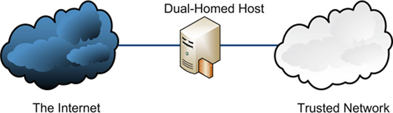
Figure 5.28 Dual-Homed Host
Screened Host Architecture
Screened host architecture is an older flat network design using one router to filter external traffic to and from a bastion host via an access control list (ACL). The bastion host can reach other internal resources, but the router ACL forbids direct internal/external connectivity, as shown in Figure 5.29.

Figure 5.29 Screened Host Network
The difference between dual-homed host and screened host design is screened host uses a screening router, which filters Internet traffic to other internal systems. Screened host network design does not employ network defense-in-depth: a failure of the bastion host puts the entire trusted network at risk. Screened subnet architecture evolved as a result, using network defense in depth via the use of DMZ networks.
DMZ Networks and Screened Subnet Architecture
A DMZ is a Demilitarized Zone network; the name is based on real-world military DMZ, such as the DMZ between North Korea and South Korea. A DMZ is a dangerous “no-man’s land”: this is true for both military and network DMZ.
Any server that receives traffic from an untrusted source such as the Internet is at risk of being compromised. We use defense-in-depth mitigation strategies to lower this risk, including patching, server hardening, NIDS, etc., but some risk always remains.
Network servers that receive traffic from untrusted networks such as the Internet should be placed on DMZ networks for this reason. A DMZ is designed with the assumption that any DMZ host may be compromised: the DMZ is designed to contain the compromise, and prevent it from extending into internal trusted networks. Any host on a DMZ should be hardened. Hardening should consider attacks from untrusted networks, as well as attacks from compromised DMZ hosts.
A “classic” DMZ uses two firewalls, as shown in Figure 5.30. This is called screened subnet dual firewall design: two firewalls screen the DMZ subnet.
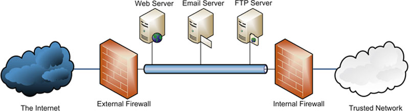
Figure 5.30 Screened Subnet Dual Firewall DMZ Design
A single-firewall DMZ uses one firewall, as shown in Figure 5.31. This is sometimes called a “three-legged” DMZ.
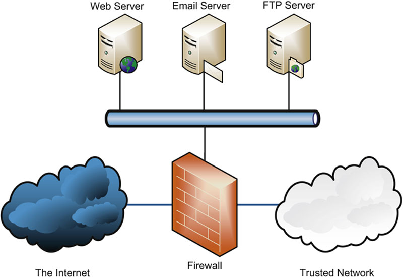
Figure 5.31 Single Firewall DMZ Design
The single firewall design requires a firewall that can filter traffic on all interfaces: untrusted, trusted, and DMZ. Dual-firewall designs are more complex, but considered more secure. In the event of compromise due to firewall failure, a dual firewall DMZ requires two firewall failures before the trusted network is exposed. Single firewall design requires one failure.
Modem
A Modem is a Modulator/Demodulator. It takes binary data and modulates it into analog sound that can be carried on phone networks designed to carry the human voice. The receiving modem then demodulates the analog sound back into binary data. Modems are asynchronous devices: they do not operate with a clock signal.
DTE/DCE and CSU/DSU
A DTE (Data Terminal Equipment) is a network “terminal,” meaning any type of network-connected user machine, such as a desktop, server, or actual terminal. A DCE (Data Circuit-Terminating Equipment, or sometimes called Data Communications Equipment) is a device that networks DTEs, such as a router. The most common use of these terms is DTE/DCE, and the meaning of each is more specific: the DCE marks the end of an ISP’s network. It connects to Data Terminal Equipment (DTE), which is the responsibility of the customer. The point where the DCE meets the DTE is called the demarc: the demarcation point, where the ISP’s responsibility ends, and the customer’s begins.
The circuit carried via DCE/DTE is synchronous (it uses a clock signal). Both sides must synchronize to a clock signal, provided by the DCE. The DCE device is a modem or a CSU/DSU (Channel Service Unit/Data Service Unit).
Secure Communications
Protecting data in motion is one of the most complex challenges we face. The Internet provides cheap global communication—with little or no built-in confidentiality, integrity, or availability. To secure our data, we often must do it ourselves; secure communications describes ways to accomplish that goal.
Authentication Protocols and Frameworks
An authentication protocol authenticates an identity claim over the network. Good security design assumes that a network eavesdropper may sniff all packets sent between the client and authentication server: the protocol should remain secure. As we will see shortly, PAP fails this test, but CHAP and EAP pass.
PAP & CHAP
PAP (Password Authentication Protocol) is a very weak authentication protocol. It sends the username and password in cleartext. An attacker who is able to sniff the authentication process can launch a simple replay attack, by replaying the username and password, using them to log in. PAP is insecure and should not be used.
CHAP (Challenge-Handshake Authentication Protocol) is a more secure authentication protocol that does not expose the cleartext password, and is not susceptible to replay attacks. CHAP relies on a shared secret: the password. The password is securely created (such as during account enrollment) and stored on the CHAP server. Since both the user and the CHAP server share a secret (the plaintext password), they can use that secret to securely communicate.
To authenticate, the client first creates an initial (unauthenticated) connection via LCP (Link Control Protocol). The server then begins the three-way CHAP authentication process:
1. Server sends a challenge, which is a small random string (also called a nonce).
2. The user takes the challenge string and the password, uses a hash cipher such as MD5 to create a hash value, and sends that value back to the CHAP server as the response.
3. The CHAP server also hashes the password and challenge, creating the expected response. It then compares the expected response with the response received from the user.
If the responses are identical, the user must have entered the appropriate password, and is authenticated. If they are different, the user entered the wrong password, and access is denied.
The CHAP server may re-authenticate by sending a new (and different) challenge. The challenges must be different each time; otherwise an attacker could authenticate by replaying an older encrypted response.
A drawback of CHAP is that the server stores plaintext passwords of each client. An attacker who compromises a CHAP server may be able to steal all the passwords stored on it.
802.1X and EAP
802.1X is “Port Based Network Access Control,” and includes EAP (Extensible Authentication Protocol). EAP is an authentication framework that describes many specific authentication protocols. EAP is designed to provide authentication at Layer 2 (it is “port based,” like ports on a switch), before a node receives an IP address. It is available for both wired and wireless, but is more commonly deployed on WLANs.
The major 802.1X roles are:
• Supplicant: An 802.1X client
• Authentication Server (AS): a server that authenticates a supplicant
• Authenticator: a device such as an access point that allows a supplicant to authenticate and connect
EAP addresses many issues, including the “roaming infected laptop” problem. A user with an infected laptop plugs into a typical office network and requests an IP address from a DHCP server. Once given an IP, the malware installed on the laptop begins attacking other systems on the network.
By the time the laptop is in a position to request an IP address, it is already in a position to cause harm on the network, including confidentiality, integrity, and availability attacks. This problem is most acute on WLANs (where an outside laptop 100 feet away from a building may be able to access the network). Ideally, authentication should be required before the laptop can join the network: EAP does exactly this.
Figure 5.32 shows a supplicant successfully authenticating and connecting to an internal network. Step 1 shows the Supplicant authenticating via EAPOL (EAP Over LAN), a Layer 2 EAP implementation. Step 2 shows the Authenticator receiving the EAPOL traffic, and using RADIUS or Diameter to carry EAP traffic to the Authentication Server (AS). Step 3 shows the Authenticator allowing Supplicant access to the internal network after successful authentication.
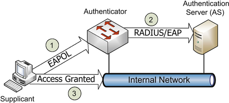
Figure 5.32 Successful 802.1X Authentication
There are many types of EAP; we will focus on EAP-MD5, LEAP, EAP-FAST, EAP-TLS, EAP-TTLS, and PEAP:
• EAP-MD5 is one of the weakest forms of EAP. It offers client → server authentication only (all other forms of EAP discussed in this section support mutual authentication of client and server); this makes it vulnerable to man-in-the-middle attacks. EAP-MD5 is also vulnerable to password cracking attacks.
• LEAP (Lightweight Extensible Authentication Protocol) is a Cisco-proprietary protocol released before 802.1X was finalized. LEAP has significant security flaws, and should not be used.
• EAP-FAST (EAP-Flexible Authentication via Secure Tunneling) was designed by Cisco to replace LEAP. It uses a Protected Access Credential (PAC), which acts as a pre-shared key.
• EAP-TLS (EAP-Transport Layer Security) uses PKI, requiring both server-side and client-side certificates. EAP-TLS establishes a secure TLS tunnel used for authentication. EAP-TLS is very secure due to the use of PKI, but is complex and costly for the same reason. The other major versions of EAP attempt to create the same TLS tunnel without requiring a client-side certificate.
• EAP-TTLS (EAP Tunneled Transport Layer Security), developed by Funk Software and Certicom, simplifies EAP-TLS by dropping the client-side certificate requirement, allowing other authentication methods (such as password) for client-side authentication. EAP-TTLS is thus easier to deploy than EAP-TLS, but less secure when omitting the client-side certificate.
• PEAP (Protected EAP), developed by Cisco Systems, Microsoft, and RSA Security, is similar to (and may be considered a competitor to) EAP-TTLS, including not requiring client-side certificates.
VPN
Virtual Private Networks (VPNs) secure data sent via insecure networks such as the Internet. The goal is to provide the privacy provided by a circuit such as a T1, virtually. The nuts and bolts of VPNs involve secure authentication, cryptographic hashes such as SHA-1 to provide integrity, and ciphers such as AES to provide confidentiality.
SLIP and PPP
SLIP (Serial Line Internet Protocol) is a Layer 2 protocol that provides IP connectivity via asynchronous connections such as serial lines and modems. When SLIP was first introduced in 1988, it allowed routing packets via modem links for the first time (previously, modems were primarily used for non-routed terminal access). SLIP is a bare-bones protocol that provides no built-in confidentiality, integrity, or authentication. SLIP has largely faded from use, replaced with PPP.
PPP (Point-to-Point Protocol) is a Layer 2 protocol that has largely replaced SLIP. PPP is based on HDLC (discussed previously), and adds confidentiality, integrity, and authentication via point-to-point links. PPP supports synchronous links (such as T1s) in addition to asynchronous links such as modems.
PPTP and L2TP
PPTP (Point-to-Point Tunneling Protocol) tunnels PPP via IP. A consortium of vendors, including Microsoft, 3COM, and others, developed it. PPTP uses GRE (Generic Routing Encapsulation) to pass PPP via IP, and uses TCP for a control channel (using TCP port 1723).
L2TP (Layer 2 Tunneling Protocol) combines PPTP and L2F (Layer 2 Forwarding, designed to tunnel PPP). L2TP focuses on authentication and does not provide confidentiality: it is frequently used with IPsec to provide encryption. Unlike PPTP, L2TP can also be used on non-IP networks, such as ATM.
IPsec
IPv4 has no built-in confidentiality; higher-layer protocols such as TLS are used to provide security. To address this lack of security at Layer 3, IPsec (Internet Protocol Security) was designed to provide confidentiality, integrity, and authentication via encryption for IPv6. IPsec has been ported to IPv4. IPsec is a suite of protocols; the major two are Encapsulating Security Protocol (ESP) and Authentication Header (AH). Each has an IP protocol number: ESP is protocol 50; AH is protocol 51.
IPsec Architectures
IPsec has three architectures: host-to-gateway, gateway-to-gateway, and host-to-host. Host-to-gateway mode (also called client mode) is used to connect one system that runs IPsec client software to an IPsec gateway. Gateway-to-gateway (also called point-to-point) connects two IPsec gateways, which form an IPsec connection that acts as a shared routable network connection, like a T1. Finally, host-to-host mode connects two systems (such as file servers) to each other via IPsec. Many modern operating systems, such as Windows 10 or Ubuntu Linux, can run IPsec natively, allowing them to form host-to-gateway or host-to-host connections.
Tunnel and Transport Mode
IPsec can be used in tunnel mode or transport mode. Tunnel mode provides confidentiality (ESP) and/or authentication (AH) to the entire original packet, including the original IP headers. New IP headers are added (with the source and destination addresses of the IPsec gateways). Transport mode protects the IP data (layers 4-7) only, leaving the original IP headers unprotected. Both modes add extra IPsec headers (an AH header and/or an ESP header). Figure 5.33 shows the differences between tunnel and transport modes.

Figure 5.33 IPSec Tunnel and Transport Modes
SSL and TLS
Secure Sockets Layer (SSL) was designed to protect HTTP (Hypertext Transfer Protocol) data: HTTPS uses TCP port 443. TLS (Transport Layer Security) is the latest version of SSL, equivalent to SSL version 3.1. The current version of TLS is 1.2, described in RFC 5246 (see: http://tools.ietf.org/html/rfc5246).
Though initially Web-focused, SSL or TLS may be used to encrypt many types of data, and can be used to tunnel other IP protocols to form VPN connections. SSL VPNs can be simpler than their IPsec equivalents: IPsec makes fundamental changes to IP networking, so installation of IPsec software changes the operating system (which requires super-user privileges). SSL client software does not require altering the operating system. Also, IPsec is difficult to firewall; SSL is much simpler.
Remote Access
In an age of telecommuting and the mobile workforce, secure remote access is a critical control. This includes connecting mobile users via methods such as DSL or Cable Modem, security mechanisms such as callback, and newer concerns such as instant messaging and remote meeting technology.
ISDN
Integrated Services Digital Network (ISDN) was an earlier attempt to provide digital service via “copper pair,” the POTS (Plain Old Telephone Service) prevalent in homes and small offices around the world. This is called the “last mile”; providing high-speed digital service via the (historically copper pair) last mile has been a longstanding challenge.
ISDN devices are called terminals. ISDN Basic Rate Interface (BRI) service provides two 64K digital channels (plus a 16K signaling channel) via copper pair. A PRI (Primary Rate Interface) provides twenty-three 64K channels, plus one 16K signaling channel.
ISDN never found widespread home use; it was soon eclipsed by DSL and cable modems. ISDN is commonly used for teleconferencing and videoconferencing.
DSL
Digital Subscriber Line (DSL) has a “last mile” solution similar to ISDN: use existing copper pairs to provide digital service to homes and small offices. DSL has found more widespread use due to higher speeds compared with ISDN, reaching speeds of 10 megabits and more.
Common types of DSL are Symmetric Digital Subscriber Line (SDSL, with matching upload and download speeds), Asymmetric Digital Subscriber Line (ADSL, featuring faster download speeds than upload), and Very High Rate Digital Subscriber Line (VDSL, featuring much faster asymmetric speeds). Another option is HDSL (High-data-rate DSL), which matches SDSL speeds using two pairs of copper; HDSL is used to provide inexpensive T1 service.
Symmetric DSL is also called Single-Line DSL. An advantage of ADSL is that it allows the simultaneous use of a POTS line, often filtered from the DSL traffic. As a general rule, the closer a site is to the Central Office (CO), the faster the available service.
Table 5.9 summarizes the speeds and modes of DSL.
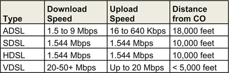
Cable Modems
Cable modems are used by Cable TV providers to provide Internet access via broadband cable TV. Cable TV access is not ubiquitous, but is available in most large towns and cities in industrialized areas. Broadband, unlike baseband, has multiple channels (like TV channels), so dedicating bandwidth for network services requires dedicating channels for that purpose. Cable modems provide a compelling “last mile” solution for the Cable TV companies: they have already invested in connecting the last mile, and the Internet service offers another revenue stream based on that investment.
Unlike DSL, Cable Modem bandwidth is typically shared with neighbors on the same network segment.
Callback & Caller ID
Callback is a modem-based authentication system. When a callback account is created, the modem number the user will call from is entered into the account. The user later connects via modem and authenticates. The system hangs up, and calls the user back at the preconfigured number.
Caller ID is a similar method: in addition to username and password, it requires calling from the correct phone number. Caller ID can be easily forged: many phone providers allow the end user to select any Caller ID number of their choice. This makes Caller ID a weak form of authentication.
Remote Desktop Console Access
Many users require remote access to computers’ consoles. Naturally, some form of secure conduit like an IPSec VPN, SSH, or SSL tunnel should be used to ensure confidentiality of the connection, especially if the connection originates from outside the organization. See the VPN section above for additional details on this layer of the remote console access.
Remotely accessing consoles has been common practice for decades with protocols such as the clear-text and poorly authenticated rlogin and rsh on Unix-like operating systems, which leverage TCP port 513 and TCP port 514, respectively. Two common modern protocols providing for remote access to a desktop are Virtual Network Computing (VNC), which typically runs on TCP 5900 and Remote Desktop Protocol (RDP), which typically runs on TCP port 3389. VNC and RDP allow for graphical access of remote systems, as opposed to the older terminal-based approach to remote access. RDP is a proprietary Microsoft protocol.
Increasingly, users are expecting easy access to a graphical desktop over the Internet that can be established quickly and from any number of personal devices. These expectations can prove difficult with traditional VNC and RDP based approaches, which, for security purposes, are frequently tunneled over an encrypted channel such as a VPN.
A recent alternative to these approaches is to use a reverse tunnel, which allows a user who established an outbound encrypted tunnel to connect back in through the same tunnel. This usually requires a small agent installed on the user’s computer that will initiate an outbound connection using HTTPS over TCP 443. This connection will terminate at a central server, which the user can authenticate to (from outside the office) to take control of their office desktop machine. Two of the most prominent solutions that employ this style of approach are Citrix’ GoToMyPC and LogMeIn.
Desktop and Application Virtualization
In addition to accessing standalone desktop systems remotely, another approach to providing remote access to computing resources is through desktop and application virtualization. Desktop virtualization is an approach that provides a centralized infrastructure that hosts a desktop image that can be remotely leveraged by the workforce. Desktop virtualization is often referred to as VDI, which, depending on the vendor in question, stands for either Virtual Desktop Infrastructure or Virtual Desktop Interface.
As opposed to providing a full desktop environment, an organization can choose to simply virtualize key applications that will be served centrally. Like desktop virtualization, the centralized control associated with application virtualization allows the organization to employ strict access control, and perhaps more quickly patch the application. Additionally, application virtualization can also be used to run legacy applications that would otherwise be unable to run on the systems employed by the workforce.
While the terms and particulars of the approach are relatively new, the underlying concepts of both desktop and application virtualization have existed for decades in the form of thin clients, mainframes, and terminal servers. The main premise of both the refreshed and more traditional approaches is that there might be organizational benefits to having more centralized and consolidated computing systems and infrastructure rather than a large number of more complex systems. In addition to general “economies of scale” justifications, there could be security advantages too from more tightly controlled desktop and application environments. Patching more complex applications in a centralized environment can be easier to manage. Likewise, developing and maintaining desktops to a security baseline can be easier to accomplish when there is one, or even several, central master images that determine the settings of each corresponding virtual desktop.
Screen Scraping
Screen scraping presents one approach to graphical remote access to systems. Screen scraping protocols packetize and transmit information necessary to draw the accessed system’s screen on the display of the system being used for remote access. VNC (Virtual Network Computing), a commonly used technology for accessing remote desktops, is fundamentally a screen scraping style approach to remote access. Not all remote access protocols are built as screen scrapers. For example, Microsoft’s popular Remote Desktop Protocol (RDP), does not employ screen scraping to provide graphical remote access.
Instant Messaging
Instant Messaging allows two or more users to communicate with each other via real-time “chat.” Chat may be one-to-one, or many-to-many via chat groups. In addition to chatting, most modern instant messaging software allows file sharing, and sometimes audio and video conferencing.
An older instant messaging protocol is IRC (Internet Relay Chat), a global network of chat servers and clients created in 1988 and remaining very popular even today. IRC servers use TCP port 6667 by default, but many IRC servers run on nonstandard ports. IRC can be used for legitimate purposes, but is also used by malware, which may “phone home” to a command-and-control channel via IRC (among other methods).
Other chat protocols and networks include AOL Instant Messenger (AIM), ICQ (short for “I seek you”), and Extensible Messaging and Presence Protocol (XMPP) (formerly known as Jabber).
Chat software may be subject to various security issues, including remote exploitation, and must be patched like any other software. The file sharing capability of chat software may allow users to violate policy by distributing sensitive documents, and similar issues can be raised by the audio and video sharing capability of many of these programs. Organizations should have a policy controlling the use of chat software and technical controls in place to monitor and, if necessary, block their usage.
Remote Meeting Technology
Remote meeting technology is a newer technology that allows users to conduct online meetings via the Internet, including desktop sharing functionality. Two commercial remote meeting solutions are “GoToMeeting” by Citrix Systems, and Microsoft Office Live Meeting. These technologies usually include displaying PowerPoint slides on all PCs connected to a meeting, sharing documents such as spreadsheets, and sometimes sharing audio or video. Some solutions allow users to remotely control another connected PC.
Many of these solutions are designed to tunnel through outbound SSL or TLS traffic, which can often pass via firewalls and any Web proxies. If a site’s remote access policy requires an IPsec VPN connection using strong authentication to allow remote control of an internal PC, these solutions may bypass existing controls (such as a requirement for strong authentication) and violate policy. Usage of remote meeting technologies should be understood, controlled, and compliant with all applicable policy.
PDAs
Personal Digital Assistants (PDAs) are small networked computers that can fit in the palm of your hand. PDAs have evolved over the years, beginning with first-generation devices such as the Apple Newton (Apple coined the term “PDA”) and Palm Pilot. They offered features such as calendar and note-taking capability. PDA operating systems include Apple iOS, Windows Mobile, Blackberry, and Google’s Android, among others.
PDAs have become increasingly networked, offering 802.11 and in some cases cellular networking. PDAs have become so powerful that they are sometimes used as desktop or laptop replacements. Note that the term “PDA” has become dated (“mobile device” is more common), but is still used on the exam.
Some devices, such as the Apple iPod, remain dedicated PDAs (with audio and video capability). Most PDAs have converged with cell phones into devices called smart phones (such as the Apple iPhone and Blackberry smart phones).
Two major issues regarding PDA security are loss of data due to theft or loss of the device, and wireless security. Sensitive data on PDAs should be encrypted, or the device itself should store minimal amount of data. A PIN should be used to lock the device, and the device offering remote wipe capability (the ability to remotely erase the device in case of loss or theft) is an important control.
PDAs should use secure wireless connections. If Bluetooth is used, sensitive devices should have automatic discovery disabled, and owners should consider the Bluetooth risks discussed in the previous section.
Wireless Application Protocol
The Wireless Application Protocol (WAP) was designed to provide secure Web services to handheld wireless devices such as smart phones. WAP is based on HTML, and includes HDML (Handheld Device Markup Language). Authentication is provided by Wireless Transport Layer Security (WTLS), which is based on TLS.
A WAP browser is a microbrowser, simpler than a full Web browser, and requiring fewer resources. It connects to a WAP gateway, which is a proxy server designed to translate Web pages. The microbrowser accesses sites written (or converted to) WML (Wireless Markup Language), which is based on XML.
Content Distribution Networks
Content Distribution Networks (CDN, also called Content Delivery Networks) use a series of distributed caching servers to improve performance and lower the latency of downloaded online content. They automatically determine the servers closest to end users, so users download content from the fastest and closest servers on the Internet. Examples include Akamai, Amazon CloudFront, CloudFlare and Microsoft Azure.
CDNs also increase availability and can reduce the effects of denial of service attacks: “While content delivery networks also solve ancillary problems such as improving global availability and reducing bandwidth, the main problem they address is latency: the amount of time it takes for the host server to receive, process, and deliver on a request for a page resource (images, CSS files, etc.). Latency depends largely on how far away the user is from the server, and it’s compounded by the number of resources a web page contains.
For example, if all your resources are hosted in San Francisco, and a user is visiting your page in London, then each request has to make a long round trip from London to SF and back to London. If your web page contains 100 objects (which is at the low end of normal), then your user’s browser has to make 100 individual requests to your server in order to retrieve those objects.
Typically, latency is in the 75–140ms range, but it can be significantly higher, especially for mobile users accessing a site over a 3G network. This can easily add up to 2 or 3 seconds of load time, which is a big deal when you consider that this is just one factor among many that can slow down your pages. [11]
Summary of Exam Objectives
Communication and Network Security is a large and complex domain, requiring broad and sometimes deep understanding of thorny technical issues. Our modern world relies on networks, and those networks must be kept secure. It is important to not only understand why we use concepts like packet-switched networks and the OSI model, but also how we implement those concepts.
Older Internet-connected networks often had a single dual-homed host connected to the Internet. We have seen how networks have evolved to screened host networks via the addition of a router to screened subnet via the use of DMZs. Firewalls were created, and then evolved from packet filter to stateful. Our physical design evolved from buses to stars, providing fault tolerance and hardware isolation. We have evolved from hubs to switches that provide traffic isolation. We have added detective devices such as HIDS and NIDS and preventive devices such as HIPS and NIPS. We have deployed secure protocols such as TLS and IPsec.
We have improved our network defense-in-depth every step of the way, and increased the confidentiality, integrity, and availability of our network data.
Self Test
1. Which protocol should be used for an audio streaming server, where some loss is acceptable?
A. IP
B. ICMP
C. TCP
D. UDP
2. What network technology uses fixed-length cells to carry data?
A. ARCNET
B. ATM
C. Ethernet
D. FDDI
3. Secure Shell (SSH) servers listen on what port and protocol?
A. TCP port 20
B. TCP port 21
C. TCP port 22
D. TCP port 23
4. What network cable type can transmit the most data at the longest distance?
A. Coaxial
B. Fiber Optic
C. Shielded Twisted Pair (STP)
D. Unshielded Twisted Pair (UTP)
5. Which device operates at Layer 2 of the OSI model?
A. Hub
B. Firewall
C. Switch
D. Router
6. What are the names of the OSI model, in order from bottom to top?
A. Physical, Data Link, Transport, Network, Session, Presentation, Application
B. Physical, Network, Data Link, Transport, Session, Presentation, Application
C. Physical, Data Link, Network, Transport, Session, Presentation, Application
D. Physical, Data Link, Network, Transport, Presentation, Session, Application
7. Which of the following authentication protocols uses a three-way authentication handshake?
A. CHAP
B. EAP
C. Kerberos
D. PAP
8. Restricting Bluetooth device discovery relies on the secrecy of what?
A. MAC Address
B. Symmetric key
C. Private Key
D. Public Key
9. Which wireless security protocol is also known as the RSN (Robust Security Network), and implements the full 802.11i standard?
A. AES
B. WEP
C. WPA
D. WPA2
10. Which endpoint security technique is the most likely to prevent a previously unknown attack from being successful?
A. Signature-based antivirus
B. Host Intrusion Detection Systems (HIDS)
C. Application Whitelisting
D. Perimeter firewall
11. Which transmission mode is supported by both HDLC and SDLC?
A. Asynchronous Balanced Mode (ABM)
B. Asynchronous Response Mode (ARM)
C. Normal Balanced Mode (NBM)
D. Normal Response Mode (NRM)
12. What is the most secure type of EAP?
A. EAP-TLS
B. EAP-TTLS
C. LEAP
D. PEAP
13. What WAN Protocol has no error recovery, relying on higher-level protocols to provide reliability?
A. ATM
B. Frame Relay
C. SMDS
D. X.25
14. What is the most secure type of firewall?
A. Packet Filter
B. Stateful Firewall
C. Circuit-level Proxy Firewall
D. Application-layer Proxy Firewall
15. Accessing an IPv6 network via an IPv4 network is called what?
A. CIDR
B. NAT
C. Translation
D. Tunneling
Self Test Quick Answer Key
1. D
2. B
3. C
4. B
5. C
6. C
7. A
8. A
9. D
10. C
11. D
12. A
13. B
14. D
15. D
..................Content has been hidden....................
You can't read the all page of ebook, please click here login for view all page.